US7158446B2 - Directional acoustic telemetry receiver - Google Patents
Directional acoustic telemetry receiver Download PDFInfo
- Publication number
- US7158446B2 US7158446B2 US10/897,559 US89755904A US7158446B2 US 7158446 B2 US7158446 B2 US 7158446B2 US 89755904 A US89755904 A US 89755904A US 7158446 B2 US7158446 B2 US 7158446B2
- Authority
- US
- United States
- Prior art keywords
- acoustic
- signal
- tubing
- communication signal
- telemetry
- Prior art date
- Legal status (The legal status is an assumption and is not a legal conclusion. Google has not performed a legal analysis and makes no representation as to the accuracy of the status listed.)
- Active
Links
- 238000004891 communication Methods 0.000 claims abstract description 26
- 238000002592 echocardiography Methods 0.000 claims description 4
- 238000004519 manufacturing process Methods 0.000 claims description 4
- 238000011109 contamination Methods 0.000 claims 2
- 238000005553 drilling Methods 0.000 abstract description 34
- 238000000034 method Methods 0.000 abstract description 14
- 238000001514 detection method Methods 0.000 abstract description 8
- 230000001902 propagating effect Effects 0.000 abstract description 6
- 230000001629 suppression Effects 0.000 abstract description 5
- 230000001965 increasing effect Effects 0.000 abstract description 4
- 230000015572 biosynthetic process Effects 0.000 description 10
- 238000005755 formation reaction Methods 0.000 description 10
- 230000001934 delay Effects 0.000 description 8
- 238000012986 modification Methods 0.000 description 5
- 230000004048 modification Effects 0.000 description 5
- 230000006835 compression Effects 0.000 description 4
- 238000007906 compression Methods 0.000 description 4
- 239000012530 fluid Substances 0.000 description 4
- 230000014509 gene expression Effects 0.000 description 4
- 230000008569 process Effects 0.000 description 4
- 238000012545 processing Methods 0.000 description 4
- 230000001133 acceleration Effects 0.000 description 3
- 238000004458 analytical method Methods 0.000 description 3
- 230000005540 biological transmission Effects 0.000 description 3
- 238000010586 diagram Methods 0.000 description 3
- 230000007717 exclusion Effects 0.000 description 3
- 239000003129 oil well Substances 0.000 description 3
- 230000004044 response Effects 0.000 description 3
- 238000005070 sampling Methods 0.000 description 3
- 230000011664 signaling Effects 0.000 description 3
- 238000012546 transfer Methods 0.000 description 3
- 230000003044 adaptive effect Effects 0.000 description 2
- 238000006243 chemical reaction Methods 0.000 description 2
- 238000013461 design Methods 0.000 description 2
- 238000005516 engineering process Methods 0.000 description 2
- 239000000463 material Substances 0.000 description 2
- 238000005259 measurement Methods 0.000 description 2
- 238000007476 Maximum Likelihood Methods 0.000 description 1
- 230000009471 action Effects 0.000 description 1
- 230000006978 adaptation Effects 0.000 description 1
- 239000000654 additive Substances 0.000 description 1
- 230000000996 additive effect Effects 0.000 description 1
- 230000003321 amplification Effects 0.000 description 1
- 238000013459 approach Methods 0.000 description 1
- 230000002238 attenuated effect Effects 0.000 description 1
- 230000008901 benefit Effects 0.000 description 1
- 238000012937 correction Methods 0.000 description 1
- 238000005520 cutting process Methods 0.000 description 1
- 238000011161 development Methods 0.000 description 1
- 230000018109 developmental process Effects 0.000 description 1
- 230000000694 effects Effects 0.000 description 1
- 230000002708 enhancing effect Effects 0.000 description 1
- 230000002706 hydrostatic effect Effects 0.000 description 1
- 230000007246 mechanism Effects 0.000 description 1
- 239000002184 metal Substances 0.000 description 1
- 238000003199 nucleic acid amplification method Methods 0.000 description 1
- 230000000737 periodic effect Effects 0.000 description 1
- 239000003208 petroleum Substances 0.000 description 1
- 238000013139 quantization Methods 0.000 description 1
- 230000005855 radiation Effects 0.000 description 1
- 230000009467 reduction Effects 0.000 description 1
- 239000011435 rock Substances 0.000 description 1
- 239000000523 sample Substances 0.000 description 1
- 230000003595 spectral effect Effects 0.000 description 1
- 238000001228 spectrum Methods 0.000 description 1
- 230000007480 spreading Effects 0.000 description 1
- 238000003892 spreading Methods 0.000 description 1
- 238000012360 testing method Methods 0.000 description 1
Images


Classifications
-
- G—PHYSICS
- G01—MEASURING; TESTING
- G01V—GEOPHYSICS; GRAVITATIONAL MEASUREMENTS; DETECTING MASSES OR OBJECTS; TAGS
- G01V11/00—Prospecting or detecting by methods combining techniques covered by two or more of main groups G01V1/00 - G01V9/00
- G01V11/002—Details, e.g. power supply systems for logging instruments, transmitting or recording data, specially adapted for well logging, also if the prospecting method is irrelevant
-
- E—FIXED CONSTRUCTIONS
- E21—EARTH OR ROCK DRILLING; MINING
- E21B—EARTH OR ROCK DRILLING; OBTAINING OIL, GAS, WATER, SOLUBLE OR MELTABLE MATERIALS OR A SLURRY OF MINERALS FROM WELLS
- E21B47/00—Survey of boreholes or wells
- E21B47/12—Means for transmitting measuring-signals or control signals from the well to the surface, or from the surface to the well, e.g. for logging while drilling
- E21B47/14—Means for transmitting measuring-signals or control signals from the well to the surface, or from the surface to the well, e.g. for logging while drilling using acoustic waves
- E21B47/16—Means for transmitting measuring-signals or control signals from the well to the surface, or from the surface to the well, e.g. for logging while drilling using acoustic waves through the drill string or casing, e.g. by torsional acoustic waves
-
- G—PHYSICS
- G08—SIGNALLING
- G08C—TRANSMISSION SYSTEMS FOR MEASURED VALUES, CONTROL OR SIMILAR SIGNALS
- G08C23/00—Non-electrical signal transmission systems, e.g. optical systems
- G08C23/02—Non-electrical signal transmission systems, e.g. optical systems using infrasonic, sonic or ultrasonic waves
Definitions
- Such information typically includes characteristics of the earth formations traversed by the wellbore, along with data relating to the size and configuration of the borehole itself.
- the collection of information relating to conditions downhole, which commonly is referred to as “logging”, can be performed by several methods.
- a probe or “sonde” that houses formation sensors is lowered into the borehole after some or all of the well has been drilled, and is used to determine certain characteristics of the formations traversed by the borehole.
- the upper end of the sonde is attached to a conductive wireline that suspends the sonde in the borehole. Power is transmitted to the sensors and instrumentation in the sonde through the conductive wireline. Similarly, the instrumentation in the sonde communicates information to the surface by electrical signals transmitted through the wireline.
- the problem with obtaining downhole measurements via wireline is that the drilling assembly must be removed or “tripped” from the drilled borehole before the desired borehole information can be obtained. This can be both time-consuming and extremely costly, especially in situations where a substantial portion of the well has been drilled. In this situation, thousands of feet of tubing may need to be removed and stacked on the platform (if offshore). Typically, drilling rigs are rented by the day at a substantial cost. Consequently, the cost of drilling a well is directly proportional to the time required to complete the drilling process. Removing thousands of feet of tubing to insert a wireline logging tool can be an expensive proposition.
- MWD measurement-while-drilling
- LWD logging while drilling
- sensors or transducers are typically located at the lower end of the drill string. While drilling is in progress these sensors continuously or intermittently monitor predetermined drilling parameters and formation data and transmit the information to a surface detector by some form of telemetry.
- the downhole sensors employed in MWD applications are positioned in a cylindrical drill collar that is positioned close to the drill bit.
- the MWD system then employs a system of telemetry in which the data acquired by the sensors is transmitted to a receiver located on the surface.
- telemetry systems in the prior art which seek to transmit information regarding downhole parameters up to the surface without requiring the use of a wireline tool.
- the mud pulse system is one of the most widely used telemetry systems for MWD applications.
- the mud pulse telemetry system creates “acoustic” pressure signals in the drilling fluid that is circulated under pressure through the drill string during drilling operations.
- the information that is acquired by the downhole sensors is transmitted by suitably timing the formation of pressure pulses in the mud stream.
- the information is received and decoded by a pressure transducer and computer at the surface.
- the drilling mud pressure in the drill string is modulated by means of a valve and control mechanism, generally termed a pulser or mud pulser.
- the pulser is usually mounted in a specially adapted drill collar positioned above the drill bit.
- the generated pressure pulse travels up the mud column inside the drill string at the velocity of sound in the mud.
- the velocity may vary between approximately 3000 and 5000 feet per second.
- the rate of transmission of data is relatively slow due to pulse spreading, distortion, attenuation, modulation rate limitations, and other disruptive forces, such as the ambient noise in the drill string.
- a typical pulse rate is typically less than 10 pulses per second (10 Hz).
- a disclosed acoustic telemetry device comprises at least two acoustic sensors and an electronics module.
- a first of the acoustic sensors detects a communication signal that propagates along a tubing string in a first direction.
- a second of the acoustic sensors is configured to detect the communication signal before the first acoustic sensor.
- the electronics module combines the detection signals from the acoustic sensors to obtain a combined signal that substantially excludes signals propagating in a direction opposite to the communication signal. Such signal suppression may significantly enhance the communication signal's signal-to-noise ratio, thereby increasing channel capacity.
- the acoustic telemetry device may be configured to support logging while drilling and/or full-duplex communication.
- FIG. 1 is a schematic view of an oil well in which an acoustic telemetry system may be employed
- FIG. 2A is a view of an illustrative acoustic receiver
- FIG. 2B is a view of an illustrative acoustic transmitter
- FIG. 3 is a block diagram of a first acoustic telemetry model
- FIG. 4 is a block diagram of a second model for a multi-receiver acoustic telemetry system
- FIG. 5 is a block diagram of an illustrative receiver configuration in accordance with various system embodiments.
- FIG. 6 shows an illustrative transceiver embodiment.
- FIG. 1 shows a well during drilling operations.
- a drilling platform 2 is equipped with a derrick 4 that supports a hoist 6 .
- Drilling of oil and gas wells is carried out by a string of drill pipes connected together by “tool” joints 7 so as to form a drill string 8 .
- the hoist 6 suspends a kelly 10 that is used to lower the drill string 8 through rotary table 12 .
- Connected to the lower end of the drill string 8 is a drill bit 14 .
- the bit 14 is rotated and drilling accomplished by rotating the drill string 8 , by use of a downhole motor near the drill bit, or by both methods.
- Drilling fluid termed “mud”
- mud Drilling fluid, termed “mud”
- mud recirculation equipment 16 is pumped by mud recirculation equipment 16 through supply pipe 18 , through drilling kelly 10 , and down through the drill string 8 at high pressures and volumes to emerge through nozzles or jets in the drill bit 14 .
- the mud then travels back up the hole via the annulus formed between the exterior of the drill string 8 and the borehole wall 20 , through a blowout preventer (not specifically shown), and into a mud pit 24 on the surface.
- the drilling mud is cleaned and then recirculated by recirculation equipment 16 .
- the drilling mud is used to cool the drill bit 14 , to carry cuttings from the base of the bore to the surface, and to balance the hydrostatic pressure in the rock formations.
- downhole sensors 26 are coupled to an acoustic telemetry transmitter 28 that transmits telemetry signals in the form of acoustic vibrations in the tubing wall of drill string 8 .
- An acoustic telemetry receiver array 30 may be coupled to the kelly 10 to receive transmitted telemetry signals.
- One or more repeater modules 32 may be provided along the drill string to receive and retransmit the telemetry signals.
- the repeater modules 32 include both an acoustic telemetry receiver array and an acoustic telemetry transmitter configured similarly to receiver array 30 and the transmitter 28 .
- FIG. 2A shows an illustrative receiver array mounted on a drill string 202 .
- the receiver array includes at least two acoustic sensors 204 , 206 , spaced apart along the axis of the drill string 202 .
- acoustic sensors are known in the art including pressure, velocity, and acceleration sensors.
- Sensors 204 and 206 may comprise two-axis accelerometers that sense accelerations along the axial and circumferential directions.
- sensors 204 and 206 may comprise three-axis accelerometers that also detect acceleration in the radial direction.
- Additional sensors may be provided 90 or 180 degrees away from the sensors shown.
- a reason for employing such additional sensors stems from an improved ability to isolate and detect a single acoustic wave propagation mode to the exclusion of other propagation modes.
- a multi-sensor configuration may exhibit improved detection of axial compression waves to the exclusion of torsional waves, and conversely, may exhibit improved detection of torsional waves to the exclusion of axial compression waves.
- U.S. Pat. No. 6,370,082 entitled “Acoustic Telemetry System With Drilling Noise Cancellation” discusses one such sensor configuration.
- Additional sensors may be spaced axially along the drill string 202 .
- one reason for employing multiple, axially spaced sensors stems from an ability to screen out surface noise and improve the signal to noise ratio of the receive signal. Larger axial spacings within physical system constraints may be preferred.
- Another consideration, at least when tone burst signaling is employed, is the axial placement of the sensors relative to the end of the tool string.
- U.S. Pat. No. 6,320,820, entitled “High data rate acoustic telemetry system” discusses a sensor placement strategy for such systems.
- FIG. 2B shows an acoustic transmitter 208 mounted on drill string 202 .
- Various suitable acoustic transmitters are known in the art, as evidenced by U.S. Pat. Nos. 2,810,546, 3,588,804, 3,790,930, 3,813,656, 4,282,588, 4,283,779, 4,302,826, and 4,314,365.
- the transmitter 208 shown in FIG. 2B has a stack of piezoelectric washers 210 sandwiched between two metal flanges 212 , 214 . When the stack of piezoelectric washers 210 is driven electrically, the stack expands and contracts to produce axial compression waves that propagate axially along the drill string.
- Other transmitter configurations may be used to produce torsional waves, radial compression waves, or even transverse waves that propagate along the drill string.
- FIG. 3 shows a model 302 of an acoustic telemetry system with a single acoustic sensor.
- a digital or analog telemetry signal u(t) is modulated and converted to an acoustic wave signal x(t) by modulator block 304 .
- Adder 306 adds downhole noise n d (t) to the acoustic wave signal x(t).
- the downhole noise is caused in part by the operation of the drill bit as it crushes formation material. The crushing action creates compressional and torsional acoustic waves that propagate along the drill string in the same manner as the acoustic telemetry signal x(t).
- the propagation of the noise-contaminated telemetry signal through the drillstring is represented by block 308 .
- the drill string consists of many pipe segments, compressional acoustic waves partly reflect at the acoustic impedance mismatches caused by the pipe joints.
- the periodic structure of the drill string results in a frequency response which has multiple stopbands and passbands.
- Adder 310 adds surface noise ns(t) to the acoustic signal that reaches the surface.
- the surface noise is caused at least in part by the drive motor(s) at the surface.
- the resulting acoustic signal is converted a digital or analog receive signal y(t) by an acoustic transducer and amplifier block 312 .
- the capacity for the uplink channel can be derived for the model of FIG. 3 .
- the following notation is used: X(f) denotes the power spectral density (PSD) of the telemetry signal, Nd(f) denotes the PSD of the downhole noise, Ns(f) represents the PSD of the surface noise, and H(f) represents the frequency response (the transfer function) of the drill string.
- PSD power spectral density
- Nd(f) denotes the PSD of the downhole noise
- Ns(f) represents the PSD of the surface noise
- H(f) represents the frequency response (the transfer function) of the drill string.
- the magnitude of the transfer function is generally much less than one, with many passbands and stopbands. The attenuation is severe even in the passbands, and increases with the length of the drill string.
- the downhole and surface noise sources are assumed to be additive and Gaussian.
- the capacity depends on the SNR-like quantity inside the logarithm.
- the denominator inside the logarithm shows that the surface noise is, in effect, greatly amplified by
- an uplink capacity on the order of 1000 bits/sec can be reached for a drill string approximately 2 km in length.
- the downlink capacity is similar to equation (1).
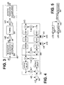
- FIG. 4 shows a more detailed model of an acoustic telemetry system with multiple receivers.
- An adder 306 contaminates the acoustic telemetry signal x(t) with downhole noise n d (t).
- One or more tubing segment blocks 404 transport the acoustic waves in two directions, introducing attenuation, delays, and reflections from the ends of each tubing segment. Eventually, the upwardly-propagating acoustic waves reach a receiver tubing segment 406 .
- the receiver tubing segment 406 also receives downwardly-propagating surface noise n s (t).
- the receiver tubing segment 406 includes at least two receivers.
- a first receiver represented by adder 408
- a second receiver is represented by an adder 410 that is sensitive to acoustic waves propagating in both directions.
- the receivers are separated by attenuation and delay blocks AD 2 (in the upward direction) and AD 5 (in the downward direction). The attenuation and delay of these blocks may be equivalent.
- the receivers may or may not be separated from the ends of the tubing segment by other attenuation and delay blocks.
- FIG. 5 shows a receiver configuration in which a signals from two receivers y 1 (t) and y 2 (t) are filtered by filter blocks 502 and 504 , respectively, before being combined by adder 506 .
- the sum may be a signal in which the surface noise is suppressed.
- a receiver block 508 receives and demodulates the signal to reconstruct the original telemetry signal u(t).
- suitable equalizers such as a linear equalizer, a fractionally-spaced equalizer, a decision feedback equalizer, and a maximum likelihood sequence estimator. These are described in detail in Chapter 6 (pp. 519–692) of John G.
- FIG. 4 An examination of FIG. 4 indicates that the surface noise signal may experience many reflections and re-reflections to create a significant number of echoes propagating in both directions.
- first-order wave reflections at the receiver tubing segment ends are taken into account, but the result generalizes when multiple reflections are considered.
- r t and r b represent reflection coefficients at the top and the bottom of the pipe segment on which the receivers are located. Attenuation is neglected, and delays in the top (AD 3 & AD 4 ), middle (AD 2 & AD 5 ), and bottom (AD 1 & AD 6 ) portions of the pipe segment are ⁇ 1 , ⁇ 2 , and ⁇ 3 , respectively.
- Equations (2) and (3) can be viewed as a system of two equations with two unknowns: (X(f)+N d (f)) and N s (f).
- H 1 ( f ) e ⁇ j2 ⁇ f ⁇ m +r b e ⁇ j2 ⁇ f( ⁇ m +2 ⁇ b )
- H 2 ( f ) 1 +r b e ⁇ j2 ⁇ f2( ⁇ m + ⁇ b ) (6)
- D ( f ) ( e +j2 ⁇ f ⁇ m +r t e ⁇ j2 ⁇ f(2 ⁇ t + ⁇ m ) )(1 +r b e ⁇ j2 ⁇ f2( ⁇
- terms of the form e ⁇ j2 ⁇ f ⁇ in expressions (5)–(7) may be expressed as e ⁇ j2 ⁇ f D n H ⁇ ( e j2 ⁇ f D ) (13) where f D denotes digital frequency.
- f D denotes digital frequency.
- the approximation is very accurate at lower frequencies.
- Better higher order allpass filter fractional delay approximations are given by modified Thiran's design technique, described in J. O. Smith, Digital Waveguide Modeling of Musical Instruments , http://www-ccrma.stanford.edu/ ⁇ tilde over ( ) ⁇ jos/waveguide, Jun. 8, 2003; and V. Välimäki, Discrete - Time Modeling of Acoustic Tubes Using Fractional Delay Filters , PhD thesis, Report no. 37, Helsinki University of Technology, Espoo, Finland, December 1995.
- the multi-receiver scheme can be viewed as attenuation of the surface noise. If both the bit and the surface noise are attenuated by some attenuation factors
- the disclosed system offers enhanced data transmission rates relative to the rate of existing acoustic telemetry systems.
- the enhancement is achieved through the suppression of noise or other interference propagating in a direction opposite that of the acoustic signal of interest. Repeaters may also be included along the drill string to extend the signaling range.
- the disclosed acoustic telemetry system may operate through continuous (coiled) tubing as well as threaded tubing, and can be employed for both MWD and LWD systems, as well as for production logging using permanently installed sensors, smart-wells, and drill stem testing.
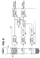
- FIG. 6 shows an illustrative transmitter/receiver (“transceiver”) embodiment 602 .
- Transceiver 602 includes an acoustic transmitter 604 , at least two acoustic sensors 606 , 608 , and transceiver electronics 610 .
- Transceiver electronics 610 may be implemented as one or more application specific integrated circuits (ASICs), or as a digital processor that executes software to perform the various functions described below.
- ASICs application specific integrated circuits
- Transceiver electronics 610 include a modulation module 612 configured to convert a downlink datastream into a transmit signal.
- a driver module 614 amplifies the transmit signal and provides the amplified signal to transmitter 604 . (In digital embodiments of electronics 610 , the driver module 614 may also provide digital-to-analog conversion.)
- An echo canceller 616 processes the transmit signal to estimate echoes not otherwise accounted for by the receive chain.
- the receive chain in transceiver electronics 610 includes sensing modules 618 , 620 that each buffer signals detected by corresponding sensors 606 , 608 .
- the sensing modules may be configured to compensate for non-linearities or other imperfections in the sensor responses.
- Sensing modules 618 , 620 may be further configured to provide analog-to-digital signal conversion.
- the receive signals from the sensor modules are filtered by filters 622 , 624 , and the filter outputs may be combined by adder 628 to provide directional detection as described previously.
- Another adder 630 may combine the directional signal from adder 628 with an estimated echo signal from echo canceller 616 to obtain an “echo-cancelled” signal.
- Demodulator 632 demodulates the echo-cancelled signal to obtain an uplink datastream.
Landscapes
- Physics & Mathematics (AREA)
- Life Sciences & Earth Sciences (AREA)
- Engineering & Computer Science (AREA)
- General Life Sciences & Earth Sciences (AREA)
- Geophysics (AREA)
- General Physics & Mathematics (AREA)
- Geology (AREA)
- Acoustics & Sound (AREA)
- Mining & Mineral Resources (AREA)
- Environmental & Geological Engineering (AREA)
- Fluid Mechanics (AREA)
- Remote Sensing (AREA)
- Geochemistry & Mineralogy (AREA)
- Geophysics And Detection Of Objects (AREA)
- Earth Drilling (AREA)
- Arrangements For Transmission Of Measured Signals (AREA)
- Transducers For Ultrasonic Waves (AREA)
Abstract
Description
-
- Provisional U.S. Patent Application No. 60/490,662, entitled “Drilling Telemetry”, filed Jul. 28, 2003; and
- Provisional U.S. Patent Application No. 60/513,679, entitled “Acoustic Telemetry Receiver Array”, filed Oct. 23, 2003.
-
- U.S. Pat. No. 6,370,082, entitled “Acoustic Telemetry System With Drilling Noise Cancellation”, issued Apr. 9, 2002;
- U.S. Pat. No. 6,583,729, entitled “High Data Rate Acoustic Telemetry System Using Multipulse Block Signaling With a Minimum Distance Receiver”, issued Jun. 24, 2003;
- U.S. patent application Ser. No. 10/364,169, entitled “Downhole Telemetry System Using Discrete Multi-Tone Modulation in a Wireless Communication Medium”, filed Feb. 10, 2003; and
Y 1(f)=(X(f)+N d(f))(1+r t e −j2πf2τ
Y 2(f)=(X(f)+N d(f))(e −j2πfτ
X(f)+N d(f)=(H 2(f)Y 2(f)−H 1(f)Y 1(f))/D(f) (4)
where
H 1(f)=e −j2πfτ
H 2(f)=1+r b e −j2πf2(τ
D(f)=(e +j2πfτ
y 1(t)=u(t)+d(t+Δt) (8)
y 2(t)=u(t+Δt)+d(t) (9)
where here u(t) represents an upwardly-propagating signal, d(t) represents a downwardly-propagating signal, and Δt represents the propagation delay between the receivers. Then the downwardly-propagating signal may be suppressed with a simple delay and subtraction:
y 1(t)−y 2(t+Δt)=u(t)+d(t+Δt)−u(t+2Δt)−d(t+Δt) (10)
y 1(t)−y 2(t+Δt)=u(t)−u(t+2 66 t) (11)
e −j2πf
where fD denotes digital frequency. The approximation is very accurate at lower frequencies. Better higher order allpass filter fractional delay approximations are given by modified Thiran's design technique, described in J. O. Smith, Digital Waveguide Modeling of Musical Instruments, http://www-ccrma.stanford.edu/{tilde over ( )}jos/waveguide, Jun. 8, 2003; and V. Välimäki, Discrete-Time Modeling of Acoustic Tubes Using Fractional Delay Filters, PhD thesis, Report no. 37, Helsinki University of Technology, Espoo, Finland, December 1995.
where
Q(f)=|G b(f)|2 N b(f)+|Gs(f)|2 N s(f)|H(f)|−2 (15)
Claims (14)
Priority Applications (6)
| Application Number | Priority Date | Filing Date | Title |
|---|---|---|---|
| US10/897,559 US7158446B2 (en) | 2003-07-28 | 2004-07-23 | Directional acoustic telemetry receiver |
| GB0706031A GB2434013B (en) | 2003-10-23 | 2004-10-21 | Directional acoustic telemetry receiver |
| GB0607651A GB2422698B (en) | 2003-10-23 | 2004-10-21 | Directional acoustic telemetry receiver |
| CA002543039A CA2543039C (en) | 2003-10-23 | 2004-10-21 | Directional acoustic telemetry receiver |
| PCT/US2004/034705 WO2005043191A2 (en) | 2003-10-23 | 2004-10-21 | Directional acoustic telemetry receiver |
| NO20061887A NO338170B1 (en) | 2003-10-23 | 2006-04-28 | Directional acoustic telemetry device and method of telemetry via the drill string |
Applications Claiming Priority (3)
| Application Number | Priority Date | Filing Date | Title |
|---|---|---|---|
| US49066203P | 2003-07-28 | 2003-07-28 | |
| US51367903P | 2003-10-23 | 2003-10-23 | |
| US10/897,559 US7158446B2 (en) | 2003-07-28 | 2004-07-23 | Directional acoustic telemetry receiver |
Publications (2)
| Publication Number | Publication Date |
|---|---|
| US20050024232A1 US20050024232A1 (en) | 2005-02-03 |
| US7158446B2 true US7158446B2 (en) | 2007-01-02 |
Family
ID=34555909
Family Applications (1)
| Application Number | Title | Priority Date | Filing Date |
|---|---|---|---|
| US10/897,559 Active US7158446B2 (en) | 2003-07-28 | 2004-07-23 | Directional acoustic telemetry receiver |
Country Status (5)
| Country | Link |
|---|---|
| US (1) | US7158446B2 (en) |
| CA (1) | CA2543039C (en) |
| GB (1) | GB2422698B (en) |
| NO (1) | NO338170B1 (en) |
| WO (1) | WO2005043191A2 (en) |
Cited By (13)
| Publication number | Priority date | Publication date | Assignee | Title |
|---|---|---|---|---|
| US20080037369A1 (en) * | 2006-08-11 | 2008-02-14 | Baker Hughes Incorporated | Pressure Waves Decoupling with Two Transducers |
| US20080074948A1 (en) * | 2006-09-22 | 2008-03-27 | Baker Hughes Incorporated | Downhole Noise Cancellation in Mud-Pulse Telemetry |
| WO2008127230A2 (en) * | 2007-04-12 | 2008-10-23 | Halliburton Energy Services, Inc. | Communication via fluid pressure modulation |
| US20080285386A1 (en) * | 2005-11-10 | 2008-11-20 | Halliburton Energy Services, Inc. | Training For Directional Detection |
| US20100148787A1 (en) * | 2005-06-20 | 2010-06-17 | Marian Morys | High Frequency or Multifrequency Resistivity Tool |
| US20100231225A1 (en) * | 2005-11-04 | 2010-09-16 | Halliburton Energy Services, Inc. | Oil Based Mud Imaging Tool with Common Mode Voltage Compensation |
| EP2354445A1 (en) | 2010-02-04 | 2011-08-10 | Services Pétroliers Schlumberger | Acoustic telemetry system for use in a drilling BHA |
| US8701784B2 (en) | 2011-07-05 | 2014-04-22 | Jonathan V. Huseman | Tongs triggering method |
| US9822634B2 (en) | 2012-02-22 | 2017-11-21 | Halliburton Energy Services, Inc. | Downhole telemetry systems and methods with time-reversal pre-equalization |
| US10641082B2 (en) | 2015-10-16 | 2020-05-05 | Halliburton Energy Services, Inc. | Measuring lengths of resizable elements downhole |
| US11286767B2 (en) | 2019-03-29 | 2022-03-29 | Halliburton Energy Services, Inc. | Accessible wellbore devices |
| US11299985B2 (en) | 2019-02-13 | 2022-04-12 | Halliburton Energy Services, Inc. | Acoustic telemetry system |
| US11566494B2 (en) | 2018-01-26 | 2023-01-31 | Halliburton Energy Services, Inc. | Retrievable well assemblies and devices |
Families Citing this family (31)
| Publication number | Priority date | Publication date | Assignee | Title |
|---|---|---|---|---|
| US7287604B2 (en) * | 2003-09-15 | 2007-10-30 | Baker Hughes Incorporated | Steerable bit assembly and methods |
| US7137690B2 (en) | 2003-10-31 | 2006-11-21 | Hewlett-Packard Development Company, L.P. | Interconnect circuit |
| US7324010B2 (en) * | 2004-11-09 | 2008-01-29 | Halliburton Energy Services, Inc. | Acoustic telemetry systems and methods with surface noise cancellation |
| US7341116B2 (en) * | 2005-01-20 | 2008-03-11 | Baker Hughes Incorporated | Drilling efficiency through beneficial management of rock stress levels via controlled oscillations of subterranean cutting elements |
| US8629782B2 (en) | 2006-05-10 | 2014-01-14 | Schlumberger Technology Corporation | System and method for using dual telemetry |
| US8004421B2 (en) * | 2006-05-10 | 2011-08-23 | Schlumberger Technology Corporation | Wellbore telemetry and noise cancellation systems and method for the same |
| WO2007095112A2 (en) * | 2006-02-14 | 2007-08-23 | Baker Hughes Incorporated | Decision feedback equalization in mud-pulse telemetry |
| US20070257809A1 (en) * | 2006-04-11 | 2007-11-08 | Xact Downhole Telemetry Inc. | Acoustic telemetry system optimization |
| US7605715B2 (en) | 2006-07-10 | 2009-10-20 | Schlumberger Technology Corporation | Electromagnetic wellbore telemetry system for tubular strings |
| US7595737B2 (en) * | 2006-07-24 | 2009-09-29 | Halliburton Energy Services, Inc. | Shear coupled acoustic telemetry system |
| US7557492B2 (en) * | 2006-07-24 | 2009-07-07 | Halliburton Energy Services, Inc. | Thermal expansion matching for acoustic telemetry system |
| US7508734B2 (en) * | 2006-12-04 | 2009-03-24 | Halliburton Energy Services, Inc. | Method and apparatus for acoustic data transmission in a subterranean well |
| US8581740B2 (en) * | 2007-03-06 | 2013-11-12 | Schlumberger Technology Corporation | Method and apparatus for communicating signals to an instrument in a wellbore |
| EP2183302A4 (en) * | 2007-09-07 | 2011-06-29 | Univ Akron | Molecule-based magnetic polymers |
| US8205686B2 (en) | 2008-09-25 | 2012-06-26 | Baker Hughes Incorporated | Drill bit with adjustable axial pad for controlling torsional fluctuations |
| US9915138B2 (en) | 2008-09-25 | 2018-03-13 | Baker Hughes, A Ge Company, Llc | Drill bit with hydraulically adjustable axial pad for controlling torsional fluctuations |
| US7971662B2 (en) | 2008-09-25 | 2011-07-05 | Baker Hughes Incorporated | Drill bit with adjustable steering pads |
| US8061455B2 (en) * | 2009-02-26 | 2011-11-22 | Baker Hughes Incorporated | Drill bit with adjustable cutters |
| DE102009002148A1 (en) * | 2009-04-02 | 2010-10-14 | Robert Bosch Gmbh | Fluid delivery device |
| US8379782B2 (en) * | 2009-06-04 | 2013-02-19 | Telefonaktiebolaget L M Ericsson (Publ) | Mobile radio channel estimation |
| US8416098B2 (en) * | 2009-07-27 | 2013-04-09 | Schlumberger Technology Corporation | Acoustic communication apparatus for use with downhole tools |
| US8087479B2 (en) * | 2009-08-04 | 2012-01-03 | Baker Hughes Incorporated | Drill bit with an adjustable steering device |
| CN101858210B (en) * | 2010-06-21 | 2013-05-15 | 中国海洋石油总公司 | Simulated test device for acoustic logging instrument |
| CN102354501B (en) * | 2011-09-27 | 2012-10-17 | 北京航空航天大学 | Unidirectional echo and noise suppression method used in drill string acoustic transmission technology |
| EP2597491A1 (en) * | 2011-11-24 | 2013-05-29 | Services Pétroliers Schlumberger | Surface communication system for communication with downhole wireless modem prior to deployment |
| US9453409B2 (en) | 2012-05-09 | 2016-09-27 | Hunt Energy Enterprises, L.L.C. | System and method for spread spectrum based drill pipe communications |
| US9982532B2 (en) | 2012-05-09 | 2018-05-29 | Hunt Energy Enterprises, L.L.C. | System and method for controlling linear movement using a tapered MR valve |
| CN102881280B (en) * | 2012-09-17 | 2014-06-11 | 北京航空航天大学 | Passive suppressing method for downhole noise and echo for sound transmission technology of drill string |
| WO2015088585A1 (en) * | 2013-12-09 | 2015-06-18 | Hunt Advanced Drilling Technologies, LLC | System and method for spread spectrum based drill pipe communications |
| US9890633B2 (en) * | 2014-10-20 | 2018-02-13 | Hunt Energy Enterprises, Llc | System and method for dual telemetry acoustic noise reduction |
| US11828172B2 (en) * | 2016-08-30 | 2023-11-28 | ExxonMobil Technology and Engineering Company | Communication networks, relay nodes for communication networks, and methods of transmitting data among a plurality of relay nodes |
Citations (21)
| Publication number | Priority date | Publication date | Assignee | Title |
|---|---|---|---|---|
| US2810546A (en) | 1952-03-25 | 1957-10-22 | Physics Corp | Drill tool telemetering systems |
| US3588804A (en) | 1969-06-16 | 1971-06-28 | Globe Universal Sciences | Telemetering system for use in boreholes |
| US3716830A (en) * | 1970-12-18 | 1973-02-13 | D Garcia | Electronic noise filter with hose reflection suppression |
| US3747059A (en) * | 1970-12-18 | 1973-07-17 | Schlumberger Technology Corp | Electronic noise filter with means for compensating for hose reflection |
| US3790930A (en) | 1971-02-08 | 1974-02-05 | American Petroscience Corp | Telemetering system for oil wells |
| US3813656A (en) | 1972-09-29 | 1974-05-28 | Texaco Inc | Methods and apparatuses for transmission of longitudinal and torque pulse data from drill string in well while drilling |
| US4282588A (en) | 1980-01-21 | 1981-08-04 | Sperry Corporation | Resonant acoustic transducer and driver system for a well drilling string communication system |
| US4283779A (en) | 1979-03-19 | 1981-08-11 | American Petroscience Corporation | Torsional wave generator |
| US4302826A (en) | 1980-01-21 | 1981-11-24 | Sperry Corporation | Resonant acoustic transducer system for a well drilling string |
| US4314365A (en) | 1980-01-21 | 1982-02-02 | Exxon Production Research Company | Acoustic transmitter and method to produce essentially longitudinal, acoustic waves |
| US4590593A (en) * | 1983-06-30 | 1986-05-20 | Nl Industries, Inc. | Electronic noise filtering system |
| US5467320A (en) * | 1993-01-08 | 1995-11-14 | Halliburton Company | Acoustic measuring method for borehole formation testing |
| US5969638A (en) * | 1998-01-27 | 1999-10-19 | Halliburton Energy Services, Inc. | Multiple transducer MWD surface signal processing |
| US6006832A (en) * | 1995-02-09 | 1999-12-28 | Baker Hughes Incorporated | Method and system for monitoring and controlling production and injection wells having permanent downhole formation evaluation sensors |
| US6088294A (en) * | 1995-01-12 | 2000-07-11 | Baker Hughes Incorporated | Drilling system with an acoustic measurement-while-driving system for determining parameters of interest and controlling the drilling direction |
| US6320820B1 (en) | 1999-09-20 | 2001-11-20 | Halliburton Energy Services, Inc. | High data rate acoustic telemetry system |
| US6370082B1 (en) | 1999-06-14 | 2002-04-09 | Halliburton Energy Services, Inc. | Acoustic telemetry system with drilling noise cancellation |
| US6583729B1 (en) | 2000-02-21 | 2003-06-24 | Halliburton Energy Services, Inc. | High data rate acoustic telemetry system using multipulse block signaling with a minimum distance receiver |
| US20040156264A1 (en) | 2003-02-10 | 2004-08-12 | Halliburton Energy Services, Inc. | Downhole telemetry system using discrete multi-tone modulation in a wireless communication medium |
| US20040206170A1 (en) | 2003-04-15 | 2004-10-21 | Halliburton Energy Services, Inc. | Method and apparatus for detecting torsional vibration with a downhole pressure sensor |
| US6837332B1 (en) * | 1999-03-22 | 2005-01-04 | Halliburton Energy Services, Inc. | Method and apparatus for cancellation of unwanted signals in MWD acoustic tools |
-
2004
- 2004-07-23 US US10/897,559 patent/US7158446B2/en active Active
- 2004-10-21 CA CA002543039A patent/CA2543039C/en active Active
- 2004-10-21 WO PCT/US2004/034705 patent/WO2005043191A2/en active Application Filing
- 2004-10-21 GB GB0607651A patent/GB2422698B/en not_active Expired - Fee Related
-
2006
- 2006-04-28 NO NO20061887A patent/NO338170B1/en unknown
Patent Citations (21)
| Publication number | Priority date | Publication date | Assignee | Title |
|---|---|---|---|---|
| US2810546A (en) | 1952-03-25 | 1957-10-22 | Physics Corp | Drill tool telemetering systems |
| US3588804A (en) | 1969-06-16 | 1971-06-28 | Globe Universal Sciences | Telemetering system for use in boreholes |
| US3716830A (en) * | 1970-12-18 | 1973-02-13 | D Garcia | Electronic noise filter with hose reflection suppression |
| US3747059A (en) * | 1970-12-18 | 1973-07-17 | Schlumberger Technology Corp | Electronic noise filter with means for compensating for hose reflection |
| US3790930A (en) | 1971-02-08 | 1974-02-05 | American Petroscience Corp | Telemetering system for oil wells |
| US3813656A (en) | 1972-09-29 | 1974-05-28 | Texaco Inc | Methods and apparatuses for transmission of longitudinal and torque pulse data from drill string in well while drilling |
| US4283779A (en) | 1979-03-19 | 1981-08-11 | American Petroscience Corporation | Torsional wave generator |
| US4282588A (en) | 1980-01-21 | 1981-08-04 | Sperry Corporation | Resonant acoustic transducer and driver system for a well drilling string communication system |
| US4302826A (en) | 1980-01-21 | 1981-11-24 | Sperry Corporation | Resonant acoustic transducer system for a well drilling string |
| US4314365A (en) | 1980-01-21 | 1982-02-02 | Exxon Production Research Company | Acoustic transmitter and method to produce essentially longitudinal, acoustic waves |
| US4590593A (en) * | 1983-06-30 | 1986-05-20 | Nl Industries, Inc. | Electronic noise filtering system |
| US5467320A (en) * | 1993-01-08 | 1995-11-14 | Halliburton Company | Acoustic measuring method for borehole formation testing |
| US6088294A (en) * | 1995-01-12 | 2000-07-11 | Baker Hughes Incorporated | Drilling system with an acoustic measurement-while-driving system for determining parameters of interest and controlling the drilling direction |
| US6006832A (en) * | 1995-02-09 | 1999-12-28 | Baker Hughes Incorporated | Method and system for monitoring and controlling production and injection wells having permanent downhole formation evaluation sensors |
| US5969638A (en) * | 1998-01-27 | 1999-10-19 | Halliburton Energy Services, Inc. | Multiple transducer MWD surface signal processing |
| US6837332B1 (en) * | 1999-03-22 | 2005-01-04 | Halliburton Energy Services, Inc. | Method and apparatus for cancellation of unwanted signals in MWD acoustic tools |
| US6370082B1 (en) | 1999-06-14 | 2002-04-09 | Halliburton Energy Services, Inc. | Acoustic telemetry system with drilling noise cancellation |
| US6320820B1 (en) | 1999-09-20 | 2001-11-20 | Halliburton Energy Services, Inc. | High data rate acoustic telemetry system |
| US6583729B1 (en) | 2000-02-21 | 2003-06-24 | Halliburton Energy Services, Inc. | High data rate acoustic telemetry system using multipulse block signaling with a minimum distance receiver |
| US20040156264A1 (en) | 2003-02-10 | 2004-08-12 | Halliburton Energy Services, Inc. | Downhole telemetry system using discrete multi-tone modulation in a wireless communication medium |
| US20040206170A1 (en) | 2003-04-15 | 2004-10-21 | Halliburton Energy Services, Inc. | Method and apparatus for detecting torsional vibration with a downhole pressure sensor |
Non-Patent Citations (3)
| Title |
|---|
| Proakis, John G., Second Edition Digital Communications, McGraw-Hill Book Company, New York, 1989, Chapter 6, pp. 519-692. |
| Smith, Julius O., Physical Audio Signal Processing: Digital Waveguide Modeling of Musical Instruments and Audio Effects, Aug. 2004 Draft, Center for Computer Research in Music and Acoustics (CCRMA), Stanford University, Web published at ttp://ccma.stanford.edu/~jos/pasp04/, 5 pages. |
| Valimaki, Vesa, Discrete-Time Modeling of Acoustic Tubes Using Fractional Delay Filters, PhD thesis, Report No. 37, Helsinki University of Technology, Espoo, Finland, Dec. 1995, 194 pages. |
Cited By (20)
| Publication number | Priority date | Publication date | Assignee | Title |
|---|---|---|---|---|
| US20100148787A1 (en) * | 2005-06-20 | 2010-06-17 | Marian Morys | High Frequency or Multifrequency Resistivity Tool |
| US8212568B2 (en) | 2005-11-04 | 2012-07-03 | Halliburton Energy Services, Inc. | Oil based mud imaging tool with common mode voltage compensation |
| US20100231225A1 (en) * | 2005-11-04 | 2010-09-16 | Halliburton Energy Services, Inc. | Oil Based Mud Imaging Tool with Common Mode Voltage Compensation |
| US8193946B2 (en) | 2005-11-10 | 2012-06-05 | Halliburton Energy Services, Inc. | Training for directional detection |
| US20080285386A1 (en) * | 2005-11-10 | 2008-11-20 | Halliburton Energy Services, Inc. | Training For Directional Detection |
| US8009511B2 (en) * | 2006-08-11 | 2011-08-30 | Baker Hughes Incorporated | Pressure waves decoupling with two transducers |
| US20080037369A1 (en) * | 2006-08-11 | 2008-02-14 | Baker Hughes Incorporated | Pressure Waves Decoupling with Two Transducers |
| US8811118B2 (en) * | 2006-09-22 | 2014-08-19 | Baker Hughes Incorporated | Downhole noise cancellation in mud-pulse telemetry |
| US20080074948A1 (en) * | 2006-09-22 | 2008-03-27 | Baker Hughes Incorporated | Downhole Noise Cancellation in Mud-Pulse Telemetry |
| US8339277B2 (en) | 2007-04-12 | 2012-12-25 | Halliburton Energy Services, Inc. | Communication via fluid pressure modulation |
| WO2008127230A2 (en) * | 2007-04-12 | 2008-10-23 | Halliburton Energy Services, Inc. | Communication via fluid pressure modulation |
| WO2008127230A3 (en) * | 2007-04-12 | 2008-12-31 | Halliburton Energy Serv Inc | Communication via fluid pressure modulation |
| WO2011095430A2 (en) | 2010-02-04 | 2011-08-11 | Services Petroliers Schlumberger | Acoustic telemetry system for use in a drilling bha |
| EP2354445A1 (en) | 2010-02-04 | 2011-08-10 | Services Pétroliers Schlumberger | Acoustic telemetry system for use in a drilling BHA |
| US8701784B2 (en) | 2011-07-05 | 2014-04-22 | Jonathan V. Huseman | Tongs triggering method |
| US9822634B2 (en) | 2012-02-22 | 2017-11-21 | Halliburton Energy Services, Inc. | Downhole telemetry systems and methods with time-reversal pre-equalization |
| US10641082B2 (en) | 2015-10-16 | 2020-05-05 | Halliburton Energy Services, Inc. | Measuring lengths of resizable elements downhole |
| US11566494B2 (en) | 2018-01-26 | 2023-01-31 | Halliburton Energy Services, Inc. | Retrievable well assemblies and devices |
| US11299985B2 (en) | 2019-02-13 | 2022-04-12 | Halliburton Energy Services, Inc. | Acoustic telemetry system |
| US11286767B2 (en) | 2019-03-29 | 2022-03-29 | Halliburton Energy Services, Inc. | Accessible wellbore devices |
Also Published As
| Publication number | Publication date |
|---|---|
| GB2422698B (en) | 2007-10-17 |
| CA2543039A1 (en) | 2005-05-12 |
| WO2005043191A2 (en) | 2005-05-12 |
| NO20061887L (en) | 2006-05-22 |
| WO2005043191A3 (en) | 2005-10-20 |
| GB0607651D0 (en) | 2006-05-31 |
| US20050024232A1 (en) | 2005-02-03 |
| GB2422698A (en) | 2006-08-02 |
| CA2543039C (en) | 2009-12-15 |
| NO338170B1 (en) | 2016-08-01 |
Similar Documents
| Publication | Publication Date | Title |
|---|---|---|
| US7158446B2 (en) | Directional acoustic telemetry receiver | |
| US8193946B2 (en) | Training for directional detection | |
| US6370082B1 (en) | Acoustic telemetry system with drilling noise cancellation | |
| US9822634B2 (en) | Downhole telemetry systems and methods with time-reversal pre-equalization | |
| US7265682B2 (en) | Joint source-channel coding for multicarrier modulation | |
| US7324010B2 (en) | Acoustic telemetry systems and methods with surface noise cancellation | |
| US7068183B2 (en) | Drill string incorporating an acoustic telemetry system employing one or more low frequency acoustic attenuators and an associated method of transmitting data | |
| US6583729B1 (en) | High data rate acoustic telemetry system using multipulse block signaling with a minimum distance receiver | |
| US6320820B1 (en) | High data rate acoustic telemetry system | |
| US9234981B2 (en) | Exploitation of sea floor rig structures to enhance measurement while drilling telemetry data | |
| US5969638A (en) | Multiple transducer MWD surface signal processing | |
| US7675814B2 (en) | Method and apparatus for generating acoustic signals with a single mode of propagation | |
| RU2419996C2 (en) | System and method of communication along noise communication channels | |
| US7210555B2 (en) | Low frequency acoustic attenuator for use in downhole applications | |
| GB2434013A (en) | Acoustic sensors exclude contamination signals from communication signals propagating in a drill string | |
| BRPI0415573B1 (en) | ACOUSTIC TELEMETRY DEVICE, TELEMETRY METHOD, AND, ACOUSTIC TELEMETRY SYSTEM |
Legal Events
| Date | Code | Title | Description |
|---|---|---|---|
| AS | Assignment |
Owner name: HALLIBURTON ENERGY SERVICES, INC., TEXAS Free format text: ASSIGNMENT OF ASSIGNORS INTEREST;ASSIGNORS:GARDNER, WALLACE R.;SINANOVIC, SINAN;JOHNSON, DON H.;AND OTHERS;REEL/FRAME:015278/0350;SIGNING DATES FROM 20041001 TO 20041012 |
|
| FEPP | Fee payment procedure |
Free format text: PAYOR NUMBER ASSIGNED (ORIGINAL EVENT CODE: ASPN); ENTITY STATUS OF PATENT OWNER: LARGE ENTITY |
|
| STCF | Information on status: patent grant |
Free format text: PATENTED CASE |
|
| FPAY | Fee payment |
Year of fee payment: 4 |
|
| FPAY | Fee payment |
Year of fee payment: 8 |
|
| MAFP | Maintenance fee payment |
Free format text: PAYMENT OF MAINTENANCE FEE, 12TH YEAR, LARGE ENTITY (ORIGINAL EVENT CODE: M1553) Year of fee payment: 12 |