US7112179B2 - Orthosis - Google Patents
Orthosis Download PDFInfo
- Publication number
- US7112179B2 US7112179B2 US10/795,892 US79589204A US7112179B2 US 7112179 B2 US7112179 B2 US 7112179B2 US 79589204 A US79589204 A US 79589204A US 7112179 B2 US7112179 B2 US 7112179B2
- Authority
- US
- United States
- Prior art keywords
- arm member
- orthosis
- joint
- extension
- extension member
- Prior art date
- Legal status (The legal status is an assumption and is not a legal conclusion. Google has not performed a legal analysis and makes no representation as to the accuracy of the status listed.)
- Expired - Lifetime, expires
Links
- 230000007423 decrease Effects 0.000 claims description 15
- 210000003857 wrist joint Anatomy 0.000 description 15
- 210000000245 forearm Anatomy 0.000 description 13
- 230000001965 increasing effect Effects 0.000 description 9
- 210000000707 wrist Anatomy 0.000 description 9
- 238000005452 bending Methods 0.000 description 7
- 208000006111 contracture Diseases 0.000 description 6
- 210000004872 soft tissue Anatomy 0.000 description 5
- 210000001519 tissue Anatomy 0.000 description 5
- 230000009286 beneficial effect Effects 0.000 description 4
- 230000006835 compression Effects 0.000 description 4
- 238000007906 compression Methods 0.000 description 4
- 230000001627 detrimental effect Effects 0.000 description 4
- 230000007246 mechanism Effects 0.000 description 4
- 238000010586 diagram Methods 0.000 description 3
- 238000001746 injection moulding Methods 0.000 description 3
- 210000001503 joint Anatomy 0.000 description 3
- 206010062575 Muscle contracture Diseases 0.000 description 2
- 230000003247 decreasing effect Effects 0.000 description 2
- 239000000463 material Substances 0.000 description 2
- 229910052782 aluminium Inorganic materials 0.000 description 1
- XAGFODPZIPBFFR-UHFFFAOYSA-N aluminium Chemical compound [Al] XAGFODPZIPBFFR-UHFFFAOYSA-N 0.000 description 1
- 210000003484 anatomy Anatomy 0.000 description 1
- 210000003423 ankle Anatomy 0.000 description 1
- 239000002131 composite material Substances 0.000 description 1
- 150000001875 compounds Chemical class 0.000 description 1
- 230000008602 contraction Effects 0.000 description 1
- 210000002310 elbow joint Anatomy 0.000 description 1
- 210000003414 extremity Anatomy 0.000 description 1
- 208000014674 injury Diseases 0.000 description 1
- 210000003041 ligament Anatomy 0.000 description 1
- 229910052751 metal Inorganic materials 0.000 description 1
- 239000002184 metal Substances 0.000 description 1
- 238000000034 method Methods 0.000 description 1
- 238000012986 modification Methods 0.000 description 1
- 230000004048 modification Effects 0.000 description 1
- 210000003205 muscle Anatomy 0.000 description 1
- 230000000399 orthopedic effect Effects 0.000 description 1
- 229920000642 polymer Polymers 0.000 description 1
- 238000010319 rehabilitative therapy Methods 0.000 description 1
- 231100000241 scar Toxicity 0.000 description 1
- 229910001220 stainless steel Inorganic materials 0.000 description 1
- 239000010935 stainless steel Substances 0.000 description 1
- 238000001356 surgical procedure Methods 0.000 description 1
- 210000002435 tendon Anatomy 0.000 description 1
- 230000008733 trauma Effects 0.000 description 1
Images


Classifications
-
- A—HUMAN NECESSITIES
- A61—MEDICAL OR VETERINARY SCIENCE; HYGIENE
- A61H—PHYSICAL THERAPY APPARATUS, e.g. DEVICES FOR LOCATING OR STIMULATING REFLEX POINTS IN THE BODY; ARTIFICIAL RESPIRATION; MASSAGE; BATHING DEVICES FOR SPECIAL THERAPEUTIC OR HYGIENIC PURPOSES OR SPECIFIC PARTS OF THE BODY
- A61H1/00—Apparatus for passive exercising; Vibrating apparatus ; Chiropractic devices, e.g. body impacting devices, external devices for briefly extending or aligning unbroken bones
- A61H1/02—Stretching or bending or torsioning apparatus for exercising
-
- A—HUMAN NECESSITIES
- A61—MEDICAL OR VETERINARY SCIENCE; HYGIENE
- A61F—FILTERS IMPLANTABLE INTO BLOOD VESSELS; PROSTHESES; DEVICES PROVIDING PATENCY TO, OR PREVENTING COLLAPSING OF, TUBULAR STRUCTURES OF THE BODY, e.g. STENTS; ORTHOPAEDIC, NURSING OR CONTRACEPTIVE DEVICES; FOMENTATION; TREATMENT OR PROTECTION OF EYES OR EARS; BANDAGES, DRESSINGS OR ABSORBENT PADS; FIRST-AID KITS
- A61F5/00—Orthopaedic methods or devices for non-surgical treatment of bones or joints; Nursing devices; Anti-rape devices
- A61F5/01—Orthopaedic devices, e.g. splints, casts or braces
- A61F5/0102—Orthopaedic devices, e.g. splints, casts or braces specially adapted for correcting deformities of the limbs or for supporting them; Ortheses, e.g. with articulations
- A61F5/013—Orthopaedic devices, e.g. splints, casts or braces specially adapted for correcting deformities of the limbs or for supporting them; Ortheses, e.g. with articulations for the arms, hands or fingers
Definitions
- the present invention relates to an adjustable orthosis for stretching tissue in the human body.
- the present invention relates to an adjustable orthosis which can be used for stretching tissue such as ligaments, tendons or muscles around a joint during flexion or extension of the joint.
- joints move in two directions, flexion and extension. Flexion is to bend the joint and extension is to straighten the joint; however, in the orthopedic convention some joints only flex.
- the ankle has dorsiflexion and plantarflexion.
- Other joints not only flex and extend, they rotate.
- the elbow joint has supination and pronation, which is rotation of the hand about the longitudinal axis of the forearm placing the palm up or the palm down.
- ROM orthoses are devices commonly used during physical rehabilitative therapy to increase the range-of-motion over which the patient can flex or extend the joint.
- Commercially available ROM orthoses are typically attached on opposite members of the joint and apply a torque to rotate the joint in opposition to the contraction. The force is gradually increased to increase the working range or angle of joint motion.
- Exemplary orthoses include U.S. Pat. No.: 6,599,263, entitled “Shoulder Orthosis;” U.S. Pat. No. 6,113,562, entitled “Shoulder Orthosis;” U.S. Pat. No. 5,848,979, entitled “Orthosis;” U.S. Pat. No.
- the present invention provides an orthosis for stretching tissue around a joint of a patient between first and second relatively pivotable body portions.
- the joint and the first and second body portions defining on one side of the joint an inner sector which decreases in angle as the joint is flexed and defining on the opposite side of the joint an outer sector which decreases in angle as the joint is extended.
- the orthosis includes a first arm member affixable to the first body portion.
- the first arm member has a first extension member extending at an angle ⁇ therefrom.
- a second arm member affixable to the second body portion is also included.
- the second arm member has a second extension member having an arcuate shape extending therefrom.
- the second and first extension members are operatively connected, such that the second extension member travels through the first extension member along an arcuate path when the second arm member is moved from a first position to a second position relative to the first arm member.
- the orthosis further includes a drive assembly for selectively moving the second extension member relative to the first extension member.
- the drive assembly is mounted onto the first extension member, engaging the second extension member.
- the drive assembly can be manually or automatically actuated to selectively move the second extension member relative to the first extension member.
- FIG. 1 is a schematic diagram of the orthosis of the present invention in a flexed position
- FIG. 2 is a schematic diagram of the orthosis of the present invention in an extended position
- FIG. 3 is a second schematic diagram of the orthosis of the present invention in a flexed position
- FIG. 4 shows an adjustable first extension member of the orthosis of the present invention
- FIG. 5 shows the adjustable first extension member of FIG. 4 in a second position
- FIG. 6 shows a segmented first extension member of the present invention
- FIG. 7 shows an arcuate first extension member of the present invention
- FIG. 8 shows an orthosis of the present invention
- FIG. 9 shows an orthosis of the present invention for flexing and extending a wrist joint in a patient
- FIG. 10 shows a non-circular arcuate shaped second extension member of the present invention
- FIG. 11 shows an alternative arcuate shaped second extension member of the present invention
- FIG. 12 shows a linear shaped second extension member of the present invention
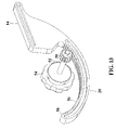
- FIG. 13 shows an exemplary drive assembly of the present invention
- FIG. 14 is a top plan view of portions of an articulating hand pad support of the present invention.
- FIG. 15 is a schematic sectional view of the articulating hand pad support of FIG. 14 .
- the present invention relates to an orthosis for moving a joint between first and second relatively pivotable body portions.
- the joint and the first and second body portions define on one side (the flexor side) of the joint an inner sector which decreases in angle as the joint is flexed (bent) and on the opposite side (the extensor side) of the joint an outer sector which decreases in angle as the joint is extended (straightened).
- the orthosis of the present invention is affixable to either the flexor or extensor side of the joint for treatment of flexion or extension contractures.
- FIG. 1 a schematic of the orthosis 10 of the present invention.
- the orthosis 10 includes a first arm member 12 attachable to the first body portion and a second arm member 14 attachable to the second body portion, wherein a joint axis of rotation 16 is interposed between and offset from the first and second arm members 12 and 14 .
- the first and second arm members 12 and 14 are operatively connected to each other offset from the joint axis 16 .
- the first arm member 12 of the orthosis 10 includes a first extension member 18 , which extends at angle ⁇ from the first arm member 12 .
- the second arm member 14 of the orthosis 10 includes a second extension member 20 extending thereform and having an arcuate shape.
- the first and second extension members 18 and 20 are operatively connected at point “P,” such that in operation the second extension member 20 travels along an arcuate path about and substantially through point “P.”
- the arcuate shape of the second extension member 20 results in the second body portion rotating about the joint axis 16 , when the second arm member 14 is moved from a first position to a second position relative to the first arm member 12 .
- the angle ⁇ between the first extension member 18 and the first arm member 12 and the radius of curvature of the second extension member 20 are a function of the joint to be treated and the degree of flexion or extension contractures.
- the orthosis further includes a drive assembly 22 at point “P.”
- the drive assembly connects the first and second extension members 18 and 20 for applying force to the first and second arm members 12 and 14 to pivot the first and second body portions relative to each other about the joint.
- the orthosis 10 of the present invention is shown having an angle ⁇ such that the operative connection, at point “P,” of the first and second extensions 18 and 20 is located in a plane “A” passing through the joint axis 16 , wherein plane “A” is substantially orthogonal to a longitudinal axis of the first arm member 12 .
- This position of point “P” provides an angle ⁇ 1 between the second arm member 14 and the joint axis 16 , wherein ⁇ 1 is the maximum angle of flexion.
- the second extension member includes a stop 24 .
- the stop 24 acts to limit the angle of maximum extension ⁇ between the second arm member 14 and the joint axis 16 .
- An increase in the length of the stop 24 will decrease the angle of maximum extension ⁇ .
- a decrease in the length of the stop 24 will increase the angle of maximum extension ⁇ .
- the maximum flexion angle can be increased by increasing the angle ⁇ .
- An increase in the angle ⁇ will move the point “P” to a location “in front of” the plane “A.”
- This position of point “P” provides an angle ⁇ 2 between the second arm member 14 and the joint axis 16 in maximum flexion, wherein ⁇ 2 is greater than ⁇ 1 .
- the greater the angle ⁇ the greater the angle of maximum flexion.
- a decrease in the angle ⁇ will move the point “P” to a location “behind” the plane “A.”
- This position of point “P” provides an angle ⁇ 3 between the second arm member 14 and the joint axis 16 in maximum flexion, wherein ⁇ 3 is less than ⁇ 1 .
- the first extension member 18 is selectively, pivotally connected at location 26 to the first arm member 12 .
- the pivotal connection 26 of the first extension member 18 permits the angle ⁇ between the first extension member 18 and the first arm member 12 to be selectively increased and decreased, increasing and decreasing the range of motion.
- a first position 28 the first extension member 18 is positioned at an angle ⁇ 1 , wherein the operative connection, at point “P,” of the first and second extension members 18 and 20 is located in a plane “A” passing through the joint axis 16 , wherein plane “A” is substantially orthogonal to a longitudinal axis of the first arm member 12 .
- the first position 28 of point “P” provides a maximum angle of flexion of ⁇ 1 .
- the second extension member stop 24 acts to limit the angle of maximum extension ⁇ 1 between the second arm member 14 and the joint axis 16 .
- a second position 30 the angle ⁇ is increased to an angle ⁇ 2 , positioning the point “P” to a location “in front of” the plane “A.”
- the second position 30 of point “P” provides a maximum angle of flexion of ⁇ 2 , wherein ⁇ 2 is greater than ⁇ 1 .
- the second extension member stop 24 acts to limit the angle of maximum extension ⁇ 2 between the second arm member 14 and the joint axis, wherein ⁇ 2 is less the ⁇ 1 .
- the selective pivotal connection 26 of the first extension member 18 to the first arm member 12 can have a plurality of selectable positions.
- the angle ⁇ between the first arm member 12 and the first extension 18 can be selectively increased to move the point “P”, on, “in front of” or “behind” the plane “A.” It is also envisioned that a positioned can be selected to increase the angle ⁇ between the first arm member 12 and the first extension 18 sufficiently to move the point “P” “in front of” plane “A” and “above” the longitudinal axis of the first arm member 12 , maximizing the maximum angle of flexion ⁇ .
- the orthosis 10 of the present invention can be connected to the flexor side of the first and second body portions of the joint, which results in a decrease in angle as the joint is flexed (bent) and an increase in angle and the joint is extended (straightened).
- orthosis 10 of the present invention can be connected to the extensor side of the joint, which results in a decrease in angle as the joint is extended straightened and an increase in angle as the joint is flexed (bent).
- first arm member 12 depicts a first extension 18 having a substantially linear shape, extending at an angle ⁇ from the first arm member 12 .
- first extension member 18 can be any shape extending from the first arm member 12 which positions the point “P” in the desired relationship to the plane “A.”
- a segmented fist extension member is shown, including a first extension member segment 18 a and a second extension member segment 18 b .
- the first and second extension member segments 18 a and 18 b extend from the first arm member 12 , positioning the point “P” at an angle ⁇ from the first arm member 12 .
- an arcuate first extension member 18 c is shown.
- the arcuate extension member 18 c extends from the first arm member 12 , positioning the point “P” at an angle ⁇ from the first arm member 12 .
- the orthosis 10 of the present invention includes a first arm member 12 attachable to the first body portion and a second arm member 14 attachable to the second body portion, wherein the joint axis 16 is interposed between and offset from the first and second arm members 12 and 14 .
- the first and second arm members 12 and 14 are connected with each other offset from the joint axis 16 .
- the first arm member 12 of the orthosis 10 includes a first extension member 18 , which extends at angle ⁇ from the first arm member 12 .
- the second arm member 14 of the orthosis 10 includes a second extension member 20 , having an arcuate shape.
- the first and second extension members 18 and 20 are operatively connected a point “P,” such that in operation the second extension member 20 travels along an arcuate path about and substantially through point “P.”
- the arcuate shape of the second extension member 20 results in the second body portion rotating about the joint axis 16 , when the second arm member 14 is moved from a first position to a second position relative to the first arm member 12 .
- the angle ⁇ between the first extension member 18 and the first arm member 12 and the radius of curvature of the second extension member 20 are a function of the joint to be treated and the degree of flexion or extension contractures.
- a first cuff 32 is attached to the first arm member 12 , wherein the first cuff 32 is positionable about the first body portion.
- the first cuff 32 is attached to the first body portion by cuff straps.
- the first cuff 32 secures the first body portion to the first arm member 12 .
- a second cuff 34 is attached to the second arm member 14 , wherein the second cuff 34 is positionable about the second body portion.
- the second cuff 34 is attached to the second body portion by cuff straps.
- the second cuff 34 secures the second body portion to the second arm member 14 .
- the orthosis 10 is operated to extend a joint in the following manner.
- the first cuff 32 is fastened about the first body portion tightly enough that the first arm member 12 may apply torque to the first body portion without having the first cuff 32 slide along the first body portion.
- the second cuff 34 is fastened securely around the second body portion so that the second arm member 14 may apply torque to the second body portion without the second cuff 34 sliding along the second body portion.
- the orthosis 10 is attached to the first and second body portions in a first position.
- the second arm member 14 is rotated from the first position to a second position, relative to the first arm member 12 , rotating the second body portion about the joint axis 16 stretching the joint.
- the second extension member 20 travels along an arcuate path about and substantially through point “P.”
- the orthosis 10 is maintained in the second position for a predetermined treatment time providing a constant stretch to the joint.
- the second arm member 14 is moved back to the first position, relieving the joint.
- the second arm member 14 can be rotated to a third position, increasing the stretch on the joint.
- the second arm member 14 can be rotated at discrete time intervals to incrementally increase the stretch of the joint through the treatment cycle.
- the second arm member is returned to the first position for removal of the orthosis 10 .
- the first and second arm members 12 and 14 are rigid members made of, for example, aluminum, stainless steel, polymeric, or composite materials.
- the arms are rigid so as to be able to transmit the necessary forces. It should be understood that any material of sufficient rigidity can be used.
- the components of the orthosis 10 of the present invention are made by injection molding.
- tool and die metal molds of the orthosis 10 components are prepared. Hot, melted plastic material is injected into the molds. The plastic is allowed to cool, forming components. The components are removed from the molds and assembled.
- the cuff portions 32 or 34 can be individual molded and attached to the arm members 12 or 14 . Alternatively, the cuff portions can be molded as an integrated part of the arm members 12 or 14 .
- the orthosis 10 can be connected to the flexor side of the first and second body portions of the joint, which results in a decrease in angle as the joint is flexed (bent) and an increase in angle as the joint is extended (straightened).
- orthosis 10 of the present invention can be connected to the extensor side of the joint, which results in a decrease in angle as the joint is extended straightened and an increase in angle as the joint is flexed (bent).
- the orthosis 10 includes a first cuff 32 for attachment to a first body portion, and a second cuff 34 for attachment to a second body portion.
- the first body portion is joined to the second body portion at a joint, around which is located, as is well known, soft tissue.
- Each of the first and second cuffs 32 and 34 includes loop connectors for receiving straps extending around the body portions to clamp the cuffs 32 and 34 to the body portions.
- the first cuff 32 is mounted for sliding movement on the first arm member 12 and is slidable along the first arm member 12 in a manner as described below.
- the second cuff 34 is mounted for sliding movement on a second arm member 14 and is slidable along the second arm member 12 in a manner as described below.
- the orthosis 10 starts at a more flexed position.
- the first and second cuffs 32 and 34 are clamped onto the first and second body portions, respectively, by straps, tightly enough so that the cuffs 32 and 34 can apply torque to the body portions to extend the joint.
- the second arm member 14 is rotated from the first position to a second position, relative to the first arm member 12 , rotating the second body portion about the joint axis 16 stretching the joint.
- the second extension member 20 travels along an arcuate path about and substantially through point “P.”
- the orthosis 10 is maintained in the second position for a predetermined treatment time providing a constant stretch to the joint.
- the first and second cuffs 32 and 34 move along the first and second arm members 12 and 14 .
- the first cuff 32 moves inwardly along the first arm member 12 .
- the second cuff 34 moves inwardly along the second arm member 14 . Because the cuffs 32 and 34 are clamped onto the first and second body portions as described above, the outward pivoting movement of the first and second arm members 12 and 14 and the cuffs 32 and 34 causes the joint to be extended as desired. However, this extension of the joint can place strong distractive forces on the soft tissues around the joint.
- the cuffs 32 and 34 slide inwardly along the first and second arm members 12 and 14 a distance far enough so that the joint is only slightly distracted during extension. Thus, the detrimental effects of strong distractive forces normally generated in forced extension of a joint are avoided, being replaced with the beneficial effects of limited and controlled distraction.
- the orthosis 10 starts at a more extended position.
- the first and second cuffs 32 and 34 are clamped onto the first and second body portions, respectively, by straps, tightly enough so that the cuffs 32 and 34 can apply torque to the body portions to extend the joint.
- the second arm member 14 is rotated from the first position to a second position, relative to the first arm member 12 , rotating the second body portion about the joint axis 16 stretching the joint.
- the second extension member 20 travels about and substantially though point “P,” along an arcuate path.
- the orthosis 10 is maintained in the second position for a predetermined treatment time providing a constant stretch to the joint.
- the first and second cuffs 32 and 34 move along the first and second arm members 12 and 14 .
- the first cuff 32 moves outwardly along the first arm member 12 .
- the second cuff 34 moves outwardly along the second arm member 14 . Because the cuffs 32 and 34 are clamped onto the first and second body portions the inward pivoting movement of the first and second arm members 12 and 14 and the cuffs 32 and 34 causes the joint to be flexed as desired. However, this flexion of the joint can place strong compressive forces on the soft tissues around the joint.
- the cuffs 32 and 34 slide outwardly along the first and second arm members 12 and 14 a distance far enough so that the joint is only slightly compressed during flexion.
- the detrimental effects of strong compressive forces normally generated in forced flexion of a joint are avoided, being replaced with the beneficial effects of limited and controlled compression.
- the orthosis 12 can be used to bend a wrist in flexion or extension.
- the orthosis 10 includes a first arm member 12 attachable to the forearm of a patient.
- the first cuff 32 is clamped onto the forearm by straps.
- a second arm member 14 operatively connected to the first arm member 12 , is attachable to the hand of the patient, wherein the axis of the wrist joint is interposed between and offset from the first and second arm members 12 and 14 .
- the second arm member 14 includes a base member 36 attach thereto.
- a hand pad 38 is attached to the base member 36 .
- the hand pad 38 is clamped onto the hand by straps, tightly enough so that the second arm member 14 can apply torque to the joint.
- the hand pad 38 can be shaped to conform to the palm or the back surface of the hand.
- the first cuff 32 When a wrist is to be bent in flexion, the first cuff 32 is connected with the forearm and the hand pad 38 is connected with the palm of the hand.
- the first cuff 32 and hand pad 38 are clamped onto the forearm and hand, respectively, by straps, tightly enough so that they can apply torque to flex the joint.
- the second arm member 14 is rotated from the first position to a second position, relative to the first arm member 12 , rotating the hand about the wrist joint axis 16 stretching the joint.
- the second extension member 20 travels along an arcuate path about and substantially through point “P.”
- the orthosis 10 is maintained in the second position for a predetermined treatment time providing a constant stretch to the wrist joint.
- the first cuff 32 is connected with the forearm and the hand pad 38 is connected with the back surface of the hand.
- the first cuff 32 and hand pad 38 are clamped onto the forearm and back surface of the hand, respectively, by straps, tightly enough so that they can apply torque to flex the joint.
- the second arm member 14 is rotated from the first position to a second position, relative to the first arm member 12 , rotating the hand about the wrist joint axis 16 stretching the joint.
- the second extension member 20 travels along an arcuate path about and substantially through point “P.”
- the orthosis 10 is maintained in the second position for a predetermined treatment time providing a constant stretch to the wrist joint.
- the hand pad 38 is removable attached to the base member 36 .
- the hand pad 38 includes a first surface, which has a substantially convex shape, to conform to the palm of the hand.
- a second surface, opposite the first surface, is also included, having a substantially concave shape, to conform to the back surface of the hand.
- the hand pad 38 can be removable attached to the base member 36 such that the first or second surfaces engages the hand of the patient.
- the hand pad 38 is removably secured to base member 36 by detent pin 40 .
- the removable securing of the hand pad 38 allows the orthosis 10 to be used for both flexion and extension of the wrist.
- the hand pad 38 In flexion, the hand pad 38 is connected to the base member 36 with the first surface facing “up” to conform to the palm of the hand.
- the hand pad 38 In extension, the hand pad 38 is connected to the base member 36 with the second surface facing “up” to conform to the back surface of the hand.
- the base member 38 can be mounted for sliding movement on the second arm member 14 and is slidable along the second arm member 14 in a manner as described below.
- the orthosis 10 starts at a more flexed position.
- the first cuff 32 is connected with the forearm and the hand pad 38 is connected with the palm of the hand.
- the first cuff 32 and hand pad 38 are clamped onto the forearm and palm of the hand so as to apply torque to extend the wrist joint.
- the second arm member 14 is rotated from the first position to a second position, relative to the first arm member 12 , rotating the hand about the wrist joint axis 16 stretching the wrist joint.
- the second extension member 20 travels along an arcuate path about and substantially through point “P.”
- the orthosis 10 is maintained in the second position for a predetermined treatment time providing a constant stretch to the joint.
- the base member 36 and hand pad 38 move along the second arm member 14 .
- the base member 36 and hand pad 38 move inwardly along the second arm member 14 .
- the cuff 32 and hand pad 38 are clamped onto the forearm and hand the outward pivoting movement of the first and second arm members 12 and 14 causes the joint to be extended as desired.
- this extension of the joint can place strong distractive forces on the soft tissues around the joint.
- the sliding movement of the base member 36 and hand pad 38 , inwardly along the second arm member 14 helps to limit these distractive forces by counteracting the outward movement of the second arm members 12 and 14 .
- the base member 36 and hand pad 38 slide inwardly along the second arm member 14 a distance far enough so that the joint is only slightly distracted during extension.
- the orthosis 10 In operation of the orthosis 10 to flex the wrist joint, the orthosis 10 starts at a more extended position.
- the first cuff 32 is connected with the forearm and the hand pad 38 is connected with the back surface of the hand.
- the first cuff 32 and hand pad 38 are clamped onto the forearm and back surface of the hand so as to apply torque to flex the wrist joint.
- the second arm member 14 is rotated from the first position to a second position, relative to the first arm member 12 , rotating the hand about the wrist joint axis 16 stretching the wrist joint.
- the second extension member 20 travels along an arcuate path about and substantially through point “P.”
- the orthosis 10 is maintained in the second position for a predefined treatment time providing a constant stretch to the joint.
- the base member 36 and hand pad 38 move along the second arm member 14 .
- the base member 36 and hand pad 38 move outwardly along the second arm member 14 .
- the inward pivoting movement of the first and second arm members 12 and 14 causes the joint to be flexed as desired.
- this flexing of the joint can place strong compressive forces on the soft tissues around the joint.
- the sliding movement of the base member 36 and hand pad 38 , outwardly along the second arm member 14 helps to limit these compressive forces by counteracting the inward movement of the first and second arm members 12 and 14 .
- the base member 36 and hand pad 38 slide outwardly along the second arm member 14 a distance far enough so that the joint is only slightly compressed during extension.
- the hand pad 38 is shown sliding inwardly and outwardly along the second arm member 14 .
- the hand pad 38 can slide in other directions.
- the hand pad 38 can slide substantially orthogonal to the second arm member 14 , wherein the substantially orthogonal directions can have an arcuate path.
- hand pad 38 can be connected to the second arm member 14 such that hand pad 38 can exhibit both longitudinal and orthogonal motion (and combinations thereof) with respect to the second arm member 14 .
- the second extension member 20 is shown and described as having a substantially circular arcuate shape, positioning the axis of rotation at the joint axis 16 .
- the second extension member 20 can have alternative shapes.
- the second arm member 14 is shown having a non-circular arcuate shaped second extension member 44 .
- the non-circular arcuate shaped second extension member 44 provide an axis of rotation which changes as the second arm member 14 is moved from the first position to the second portion. As such, as the second arm member 14 is moved from the first position to the second portion the second body portion will exhibit both a rotational motion, about the joint axis 16 , and a translational motion, distracting or compressing the joint.
- the arcuate shape of the second extension member 20 or 44 as shown have concave radius of curvature relative to the joint 16 .
- the second extension member 18 or 44 can have a convex radius of curvature relative to the joint 16 . Similar to the concave radius of curvature, the convex arcuate shape of the second extension member 18 or 44 results in the second body portion rotating about the joint axis 16 , when the second arm member 14 is moved from a first position to a second position relative to the first arm member 12 .
- the second arm member 14 of the orthosis 10 includes a second extension member 48 extending therefrom and having a linear shape.
- the first and second extension members 18 and 48 are operatively connected at point “P,” such that in operation the second extension member 48 travels along a linear path through point “P.”
- the linear shape of the second extension member 48 results in the second body portion being translated with respect to the first body portion.
- the translational movement of the second arm member 14 results is a distraction or compression of the joint when the second arm member 14 is moved from a first position to a second position relative to the first arm member 12 .
- the hand pad can be mounted for translational and rotational movement on the base member.
- the drive assembly 22 of the orthosis includes a gear system.
- the components of the orthosis, including the drive assembly 22 can be made by injection molding a polymer.
- the drive assembly 22 is supported in the first extension member 18 , including a gear 50 rotatable about point “P.”
- a shaft 52 attached to the gear 50 , extends from first extension member 18 .
- a knob 54 is connected to the shaft 52 , opposite the gear 50 , for manually rotating the gear 50 .
- the second extension member 20 includes a series of teeth 56 along an inner surface 58 .
- the second extension member 20 is threaded through the first extension member 18 , such that the teeth 56 on the second extension member 20 engage the gear 55 .
- the rotation of the knob 56 causes the gear 50 to rotate, pushing or pulling the second extension member 20 through the first extension member 18 .
- the drive assembly 22 includes a locking or breaking mechanism which prevents the gear 50 from rotating absent am applied force rotation of the knob 46 .
- a lock or breaking mechanism can include a compression washer or other known gear locking or breaking mechanisms.
- the drive assembly 22 is described as utilizing a gear system. However, it is contemplated that other known drive systems can be used to move the second extension member 20 through the first extension member 18 , for example a friction type drive system. Regardless of the drive system used, the joint orthosis of the present invention can act as a brace, restricting the relative movement of the first and second body portions to one degree of freedom (e.g. flexion and extension about the joint). Thus, drive assembly 22 can be configured to allow free motion in one degree of freedom. This can be achieved in a number of different ways. For example, gear 50 can be positioned such that it does not engage teeth 56 .
- the drive assembly 22 for an orthosis 10 in accordance with the present invention can be actuated by a motor instead of by a manually actuatable member, such as the knob 54 .
- an electric motor is mounted to the shaft 52 for rotation of the gear 50 .
- a battery provides electric power to the motor.
- the motor can be supplied with external power.
- a microprocessor controls the operation of the motor. The microprocessor and motor together can be used to cycle the first and second arm members 12 and 14 through extension and flexion; to move the first and second arm members 12 and 14 in one pivotal direction a certain amount, hold there while tissue stretches, then move further in that direction; or in any other manner.
- the orthosis can be set to cycle to one end of the joint's range of motion and hold there for a predetermined period of time, then cycle to the other end of the joint's range of motion and hold there.
- the programming and control of the microprocessor is within the skill of the art as it relates to driving the motor to control the first and second arm members 12 and 14 to move in known manners.
- This embodiment is ideally suited for continuous passive motion exercise, because the orthosis is portable and because the motor can be programmed with the desired sequence of movements.
- the second arm member 14 has a circular base member 40 attached thereto.
- the circular base member 40 supports a circular base plate 42 .
- a circular cover 44 extends upwardly from the circular base member 40 and has a portion 46 extending radially inwardly toward a vertical axis 48 to define a slide chamber 50 .
- a hand pad support slider 52 is received in the slide chamber 50 .
- the support slider 52 has an upper portion 54 to which the hand pad 38 is attached.
- the upper portion 54 is connected by a neck 56 to a circular planar portion 58 .
- Two annular bearing races 60 extend downwardly from the planar portion 58 and secure between them a plurality of ball bearings 62 .
- a washer 64 is disposed above the bearings 62 .
- the ball bearings 62 support the slider 52 and thus the hand pad 38 for sliding movement in any direction within the slide chamber 50 .
- the hand pad 38 can be made self-centering by springs 66 .
- the hand pad 38 is slidable relative to the circular base member 40 in any direction for a limited extent.
- the hand pad 38 is slidable fore and aft within the extent of travel allowed by the support slider 52 within the slide chamber 50 .
- the hand pad 38 is slidable laterally within the extent of travel allowed by the support slider 52 within the slide chamber 50 .
Landscapes
- Health & Medical Sciences (AREA)
- Animal Behavior & Ethology (AREA)
- Veterinary Medicine (AREA)
- Public Health (AREA)
- General Health & Medical Sciences (AREA)
- Life Sciences & Earth Sciences (AREA)
- Rehabilitation Therapy (AREA)
- Physical Education & Sports Medicine (AREA)
- Pain & Pain Management (AREA)
- Epidemiology (AREA)
- Nursing (AREA)
- Orthopedic Medicine & Surgery (AREA)
- Engineering & Computer Science (AREA)
- Biomedical Technology (AREA)
- Heart & Thoracic Surgery (AREA)
- Vascular Medicine (AREA)
- Prostheses (AREA)
- Rehabilitation Tools (AREA)
Abstract
Description
Claims (28)
Priority Applications (11)
| Application Number | Priority Date | Filing Date | Title |
|---|---|---|---|
| US10/795,892 US7112179B2 (en) | 2004-03-08 | 2004-03-08 | Orthosis |
| EP05724751.2A EP1722726B1 (en) | 2004-03-08 | 2005-03-07 | Orthosis |
| PCT/US2005/007269 WO2005086741A2 (en) | 2004-03-08 | 2005-03-07 | Orthosis |
| CA2557941A CA2557941C (en) | 2004-03-08 | 2005-03-07 | Orthosis for stretching tissue |
| US11/533,839 US7452342B2 (en) | 2004-03-08 | 2006-09-21 | Range of motion device |
| US12/272,436 US7981067B2 (en) | 2004-03-08 | 2008-11-17 | Range of motion device |
| US13/151,962 US8206329B2 (en) | 2004-03-08 | 2011-06-02 | Range of motion device |
| US13/494,103 US8814816B2 (en) | 2004-03-08 | 2012-06-12 | Range of motion device |
| US14/454,442 US9445966B2 (en) | 2004-03-08 | 2014-08-07 | Range of motion device |
| US14/613,945 US9314392B2 (en) | 2004-03-08 | 2015-02-04 | Range of motion device |
| US15/239,909 US20160354272A1 (en) | 2004-03-08 | 2016-08-18 | Range of motion device |
Applications Claiming Priority (1)
| Application Number | Priority Date | Filing Date | Title |
|---|---|---|---|
| US10/795,892 US7112179B2 (en) | 2004-03-08 | 2004-03-08 | Orthosis |
Related Parent Applications (1)
| Application Number | Title | Priority Date | Filing Date |
|---|---|---|---|
| US11/261,424 Continuation-In-Part US8066656B2 (en) | 2004-03-08 | 2005-10-28 | Range of motion device |
Related Child Applications (2)
| Application Number | Title | Priority Date | Filing Date |
|---|---|---|---|
| US11/261,424 Continuation-In-Part US8066656B2 (en) | 2004-03-08 | 2005-10-28 | Range of motion device |
| US11/533,839 Continuation-In-Part US7452342B2 (en) | 2004-03-08 | 2006-09-21 | Range of motion device |
Publications (2)
| Publication Number | Publication Date |
|---|---|
| US20050197605A1 US20050197605A1 (en) | 2005-09-08 |
| US7112179B2 true US7112179B2 (en) | 2006-09-26 |
Family
ID=34912541
Family Applications (1)
| Application Number | Title | Priority Date | Filing Date |
|---|---|---|---|
| US10/795,892 Expired - Lifetime US7112179B2 (en) | 2004-03-08 | 2004-03-08 | Orthosis |
Country Status (4)
| Country | Link |
|---|---|
| US (1) | US7112179B2 (en) |
| EP (1) | EP1722726B1 (en) |
| CA (1) | CA2557941C (en) |
| WO (1) | WO2005086741A2 (en) |
Cited By (24)
| Publication number | Priority date | Publication date | Assignee | Title |
|---|---|---|---|---|
| WO2008097989A2 (en) | 2007-02-05 | 2008-08-14 | Bonutti Research Inc. | Knee orthosis |
| US20100016772A1 (en) * | 2008-07-21 | 2010-01-21 | Anatomical Concepts, Inc. | Multiple function ratcheting orthotic device |
| US20100016773A1 (en) * | 2008-07-21 | 2010-01-21 | Anatomical Concepts, Inc. | Coordinated Cuff Displacement in an Orthotic Device |
| US20100069798A1 (en) * | 2008-09-15 | 2010-03-18 | Ching-Hsiang Cheng | Wearable device to assist with the movement of limbs |
| US7955285B2 (en) | 1998-06-01 | 2011-06-07 | Bonutti Research Inc. | Shoulder orthosis |
| US7981067B2 (en) | 2004-03-08 | 2011-07-19 | Bonutti Research Inc. | Range of motion device |
| US8012108B2 (en) | 2005-08-12 | 2011-09-06 | Bonutti Research, Inc. | Range of motion system and method |
| US8038637B2 (en) | 2000-09-18 | 2011-10-18 | Bonutti Research, Inc. | Finger orthosis |
| US8062241B2 (en) | 2000-12-15 | 2011-11-22 | Bonutti Research Inc | Myofascial strap |
| US8066656B2 (en) | 2005-10-28 | 2011-11-29 | Bonutti Research, Inc. | Range of motion device |
| US8251934B2 (en) | 2000-12-01 | 2012-08-28 | Bonutti Research, Inc. | Orthosis and method for cervical mobilization |
| US8273043B2 (en) | 2007-07-25 | 2012-09-25 | Bonutti Research, Inc. | Orthosis apparatus and method of using an orthosis apparatus |
| US8353294B2 (en) | 2004-06-16 | 2013-01-15 | Resmed Limited | Respiratory mask assembly |
| US8371301B2 (en) | 2000-10-19 | 2013-02-12 | Resmed R&D Germany Gmbh | Breathing mask for feeding a breathing gas to a mask user and discharge device for discharging breathing gas |
| US8402972B2 (en) | 2002-01-17 | 2013-03-26 | Resmed R&D Germany Gmbh | Breathing mask arrangement and a forehead support device for same |
| US8479738B2 (en) | 2001-10-22 | 2013-07-09 | Resmed R&D Germany Gmbh | Breathing mask arrangement as well as an application device and a forehead support device for same |
| US8875710B2 (en) | 2001-10-22 | 2014-11-04 | Resmed R&D Germany Gmbh | Application device for a breathing mask arrangement |
| US8905950B2 (en) | 2008-03-04 | 2014-12-09 | Bonutti Research, Inc. | Shoulder ROM orthosis |
| US9072853B2 (en) | 2001-09-07 | 2015-07-07 | Resmed Limited | Forehead pad for respiratory mask |
| US9402759B2 (en) | 2013-02-05 | 2016-08-02 | Bonutti Research, Inc. | Cervical traction systems and method |
| US10278881B1 (en) | 2013-12-12 | 2019-05-07 | Ermi, Inc. | Devices and methods for assisting pronation and/or supination |
| USD865086S1 (en) * | 2018-07-19 | 2019-10-29 | Gary Poillucci | Sleeve for exercise apparatus |
| US11123212B2 (en) * | 2006-03-20 | 2021-09-21 | Bonutti Research Inc. | Elbow orthosis |
| US11241353B2 (en) | 2017-11-09 | 2022-02-08 | The Curators Of The University Of Missouri | Knee flexion device and associated method of use |
Families Citing this family (6)
| Publication number | Priority date | Publication date | Assignee | Title |
|---|---|---|---|---|
| EP2786775A3 (en) | 2005-01-12 | 2014-12-17 | ResMed Ltd. | Forehead supports for facial masks |
| EP1998725A4 (en) * | 2006-03-20 | 2010-03-10 | Bonutti Res Inc | Elbow orthosis |
| AU2007299684B2 (en) | 2006-09-21 | 2012-11-01 | Bonutti Research Inc. | Range of motion device |
| US8151797B2 (en) * | 2008-10-30 | 2012-04-10 | Hsiner Company, Ltd. | Respiration mask assembly |
| US10307319B2 (en) | 2015-03-04 | 2019-06-04 | Bonutti Research, Inc. | Orthosis for range of motion |
| EP3357474A1 (en) * | 2017-02-07 | 2018-08-08 | Fundación Tecnalia Research & Innovation | Rehabilitation device for a joint |
Citations (9)
| Publication number | Priority date | Publication date | Assignee | Title |
|---|---|---|---|---|
| US4809688A (en) * | 1986-04-22 | 1989-03-07 | Empresa Cubana Importadora Y. Exportadora Of Products Medicos, T/A Medicuba | Sinergic splint for early mobilization of the flexor tendons of the hand |
| US5376091A (en) * | 1990-06-08 | 1994-12-27 | Smith & Nephew Richards, Inc. | Dynamic finger support |
| US5503619A (en) * | 1990-07-30 | 1996-04-02 | Bonutti; Peter M. | Orthosis for bending wrists |
| US5653680A (en) * | 1995-08-10 | 1997-08-05 | Cruz; Mark K. | Active wrist brace |
| US5772619A (en) * | 1995-04-07 | 1998-06-30 | Corbett; Blake | Pivotal brace for prosthesis |
| US5848979A (en) * | 1996-07-18 | 1998-12-15 | Peter M. Bonutti | Orthosis |
| US5882323A (en) * | 1997-09-18 | 1999-03-16 | Belkin; Julie | Polycentric hinged ulnar deviation hand splint |
| US6113562A (en) * | 1998-06-01 | 2000-09-05 | Peter M. Bonutti | Shoulder orthosis |
| US6142964A (en) * | 1997-03-27 | 2000-11-07 | Bodyworks Properties Limited | Multi-planar brace |
Family Cites Families (3)
| Publication number | Priority date | Publication date | Assignee | Title |
|---|---|---|---|---|
| US5685830A (en) | 1990-07-30 | 1997-11-11 | Bonutti; Peter M. | Adjustable orthosis having one-piece connector section for flexing |
| US5285773A (en) | 1990-07-30 | 1994-02-15 | Peter M. Bonutti | Orthosis with distraction through range of motion |
| US5167612A (en) | 1990-07-30 | 1992-12-01 | Bonutti Peter M | Adjustable orthosis |
-
2004
- 2004-03-08 US US10/795,892 patent/US7112179B2/en not_active Expired - Lifetime
-
2005
- 2005-03-07 WO PCT/US2005/007269 patent/WO2005086741A2/en not_active Application Discontinuation
- 2005-03-07 CA CA2557941A patent/CA2557941C/en active Active
- 2005-03-07 EP EP05724751.2A patent/EP1722726B1/en not_active Not-in-force
Patent Citations (10)
| Publication number | Priority date | Publication date | Assignee | Title |
|---|---|---|---|---|
| US4809688A (en) * | 1986-04-22 | 1989-03-07 | Empresa Cubana Importadora Y. Exportadora Of Products Medicos, T/A Medicuba | Sinergic splint for early mobilization of the flexor tendons of the hand |
| US5376091A (en) * | 1990-06-08 | 1994-12-27 | Smith & Nephew Richards, Inc. | Dynamic finger support |
| US5503619A (en) * | 1990-07-30 | 1996-04-02 | Bonutti; Peter M. | Orthosis for bending wrists |
| US5772619A (en) * | 1995-04-07 | 1998-06-30 | Corbett; Blake | Pivotal brace for prosthesis |
| US5653680A (en) * | 1995-08-10 | 1997-08-05 | Cruz; Mark K. | Active wrist brace |
| US5848979A (en) * | 1996-07-18 | 1998-12-15 | Peter M. Bonutti | Orthosis |
| US6142964A (en) * | 1997-03-27 | 2000-11-07 | Bodyworks Properties Limited | Multi-planar brace |
| US5882323A (en) * | 1997-09-18 | 1999-03-16 | Belkin; Julie | Polycentric hinged ulnar deviation hand splint |
| US6113562A (en) * | 1998-06-01 | 2000-09-05 | Peter M. Bonutti | Shoulder orthosis |
| US6599263B1 (en) * | 1998-06-01 | 2003-07-29 | Bonutti 2003 Trust A | Shoulder orthosis |
Cited By (54)
| Publication number | Priority date | Publication date | Assignee | Title |
|---|---|---|---|---|
| US7955285B2 (en) | 1998-06-01 | 2011-06-07 | Bonutti Research Inc. | Shoulder orthosis |
| US8038637B2 (en) | 2000-09-18 | 2011-10-18 | Bonutti Research, Inc. | Finger orthosis |
| US10596342B2 (en) | 2000-10-19 | 2020-03-24 | Resmed R&D Germany Gmbh | Breathing mask for feeding a breathing gas to a mask user and discharge device for discharging breathing gas |
| US8746250B2 (en) | 2000-10-19 | 2014-06-10 | Resmed R&D Germany Gmbh | Breathing mask for feeding a breathing gas to a mask user and discharge device for discharging breathing gas |
| US8371301B2 (en) | 2000-10-19 | 2013-02-12 | Resmed R&D Germany Gmbh | Breathing mask for feeding a breathing gas to a mask user and discharge device for discharging breathing gas |
| US9662467B2 (en) | 2000-10-19 | 2017-05-30 | Resmed R&D Germany Gmbh | Breathing mask for feeding a breathing gas to a mask user and discharge device for discharging breathing gas |
| US8251934B2 (en) | 2000-12-01 | 2012-08-28 | Bonutti Research, Inc. | Orthosis and method for cervical mobilization |
| US9681977B2 (en) | 2000-12-01 | 2017-06-20 | Bonutti Research, Inc. | Apparatus and method for spinal distraction |
| US8062241B2 (en) | 2000-12-15 | 2011-11-22 | Bonutti Research Inc | Myofascial strap |
| US9072853B2 (en) | 2001-09-07 | 2015-07-07 | Resmed Limited | Forehead pad for respiratory mask |
| US10195385B2 (en) | 2001-09-07 | 2019-02-05 | Resmed Limited | Forehead pad for respiratory mask |
| US9757534B2 (en) | 2001-10-22 | 2017-09-12 | Resmed R&D Germany Gmbh | Breathing mask arrangement as well as an application device and a forehead support device for same |
| US9889266B2 (en) | 2001-10-22 | 2018-02-13 | Resmed R&D Germany Gmbh | Breathing mask arrangement as well as an application device and a forehead support device for same |
| US10058671B2 (en) | 2001-10-22 | 2018-08-28 | Resmed R&D Germany Gmbh | Application device for a breathing mask arrangement |
| US8479738B2 (en) | 2001-10-22 | 2013-07-09 | Resmed R&D Germany Gmbh | Breathing mask arrangement as well as an application device and a forehead support device for same |
| US9144656B2 (en) | 2001-10-22 | 2015-09-29 | Resmed R&D Germany Gmbh | Breathing mask arrangement as well as an application device and a forehead support device for same |
| US8875710B2 (en) | 2001-10-22 | 2014-11-04 | Resmed R&D Germany Gmbh | Application device for a breathing mask arrangement |
| US10245403B2 (en) | 2001-10-22 | 2019-04-02 | RedMed R&D Germany GmbH | Breathing mask arrangement as well as an application device and a forehead support device for same |
| US9259549B2 (en) | 2002-01-17 | 2016-02-16 | Resmed R&D Germany Gmbh | Breathing mask arrangement and a forehead support device for same |
| US8402972B2 (en) | 2002-01-17 | 2013-03-26 | Resmed R&D Germany Gmbh | Breathing mask arrangement and a forehead support device for same |
| US7981067B2 (en) | 2004-03-08 | 2011-07-19 | Bonutti Research Inc. | Range of motion device |
| US9445966B2 (en) | 2004-03-08 | 2016-09-20 | Bonutti Research, Inc. | Range of motion device |
| US9314392B2 (en) | 2004-03-08 | 2016-04-19 | Bonutti Research, Inc. | Range of motion device |
| US10039893B2 (en) | 2004-06-16 | 2018-08-07 | Resmed Limited | Respiratory mask assembly |
| US9375545B2 (en) | 2004-06-16 | 2016-06-28 | Resmed Limited | Respiratory mask assembly |
| US10668241B2 (en) | 2004-06-16 | 2020-06-02 | ResMed Pty Ltd | Cushion for a respiratory mask assembly |
| US11071839B2 (en) | 2004-06-16 | 2021-07-27 | ResMed Pty Ltd | Cushion for a respiratory mask assembly |
| US8353294B2 (en) | 2004-06-16 | 2013-01-15 | Resmed Limited | Respiratory mask assembly |
| US11529489B2 (en) | 2004-06-16 | 2022-12-20 | ResMed Pty Ltd | Cushion for a respiratory mask assembly |
| US9320669B2 (en) | 2005-08-12 | 2016-04-26 | Bonutti Research, Inc. | Range of motion system |
| US8784343B2 (en) | 2005-08-12 | 2014-07-22 | Bonutti Research, Inc. | Range of motion system |
| US8012108B2 (en) | 2005-08-12 | 2011-09-06 | Bonutti Research, Inc. | Range of motion system and method |
| US9468578B2 (en) | 2005-10-28 | 2016-10-18 | Bonutti Research Inc. | Range of motion device |
| US8066656B2 (en) | 2005-10-28 | 2011-11-29 | Bonutti Research, Inc. | Range of motion device |
| US10456314B2 (en) | 2005-10-28 | 2019-10-29 | Bonutti Research, Inc. | Range of motion device |
| US20220175567A1 (en) * | 2006-03-20 | 2022-06-09 | Bonutti Research, Inc. | Elbow Orthosis |
| US11123212B2 (en) * | 2006-03-20 | 2021-09-21 | Bonutti Research Inc. | Elbow orthosis |
| US8920346B2 (en) | 2007-02-05 | 2014-12-30 | Bonutti Research Inc. | Knee orthosis |
| US9980871B2 (en) | 2007-02-05 | 2018-05-29 | Bonutti Research, Inc. | Knee orthosis |
| WO2008097989A2 (en) | 2007-02-05 | 2008-08-14 | Bonutti Research Inc. | Knee orthosis |
| US8273043B2 (en) | 2007-07-25 | 2012-09-25 | Bonutti Research, Inc. | Orthosis apparatus and method of using an orthosis apparatus |
| US8905950B2 (en) | 2008-03-04 | 2014-12-09 | Bonutti Research, Inc. | Shoulder ROM orthosis |
| US20100016772A1 (en) * | 2008-07-21 | 2010-01-21 | Anatomical Concepts, Inc. | Multiple function ratcheting orthotic device |
| US20100016773A1 (en) * | 2008-07-21 | 2010-01-21 | Anatomical Concepts, Inc. | Coordinated Cuff Displacement in an Orthotic Device |
| US7662119B2 (en) | 2008-07-21 | 2010-02-16 | Anatomical Concepts, Inc. | Multiple function ratcheting orthotic device |
| US7682323B2 (en) | 2008-07-21 | 2010-03-23 | Anatomical Concepts, Inc. | Coordinated cuff displacement in an orthotic device |
| US20100069798A1 (en) * | 2008-09-15 | 2010-03-18 | Ching-Hsiang Cheng | Wearable device to assist with the movement of limbs |
| US8409117B2 (en) | 2008-09-15 | 2013-04-02 | The Hong Kong Polytechnic University | Wearable device to assist with the movement of limbs |
| US9402759B2 (en) | 2013-02-05 | 2016-08-02 | Bonutti Research, Inc. | Cervical traction systems and method |
| US10278881B1 (en) | 2013-12-12 | 2019-05-07 | Ermi, Inc. | Devices and methods for assisting pronation and/or supination |
| US11826274B1 (en) | 2013-12-12 | 2023-11-28 | Ermi Llc | Devices and methods for assisting extension and/or flexion |
| US11666501B2 (en) | 2013-12-12 | 2023-06-06 | Ermi Llc | Devices and methods for assisting pronation and/or supination |
| US11241353B2 (en) | 2017-11-09 | 2022-02-08 | The Curators Of The University Of Missouri | Knee flexion device and associated method of use |
| USD865086S1 (en) * | 2018-07-19 | 2019-10-29 | Gary Poillucci | Sleeve for exercise apparatus |
Also Published As
| Publication number | Publication date |
|---|---|
| US20050197605A1 (en) | 2005-09-08 |
| WO2005086741A2 (en) | 2005-09-22 |
| EP1722726B1 (en) | 2013-12-04 |
| EP1722726A4 (en) | 2010-12-01 |
| CA2557941C (en) | 2014-12-09 |
| WO2005086741A3 (en) | 2005-12-22 |
| EP1722726A2 (en) | 2006-11-22 |
| CA2557941A1 (en) | 2005-09-22 |
Similar Documents
| Publication | Publication Date | Title |
|---|---|---|
| CA2557941C (en) | Orthosis for stretching tissue | |
| US20220175567A1 (en) | Elbow Orthosis | |
| US20180369052A1 (en) | Knee Orthosis | |
| US9445966B2 (en) | Range of motion device | |
| US10159590B2 (en) | Toe orthosis | |
| EP1998725A2 (en) | Elbow orthosis | |
| AU2007299684B2 (en) | Range of motion device |
Legal Events
| Date | Code | Title | Description |
|---|---|---|---|
| AS | Assignment |
Owner name: BONUTTI 2003 TRUST-PART B, ILLINOIS Free format text: ASSIGNMENT OF ASSIGNORS INTEREST;ASSIGNORS:BONUTTI, BORIS P.;BONUTTI, PETER M.;RUHOLL, KEVIN R.;REEL/FRAME:014816/0947;SIGNING DATES FROM 20040616 TO 20040618 |
|
| AS | Assignment |
Owner name: BONUTTI IP, LLC, ILLINOIS Free format text: ASSIGNMENT OF ASSIGNORS INTEREST;ASSIGNOR:THE BONUTTI 2003 TRUST-A AND THE BONUTTI 2003 TRUST-B;REEL/FRAME:015552/0342 Effective date: 20050110 Owner name: BONUTTI IP, LLC,ILLINOIS Free format text: ASSIGNMENT OF ASSIGNORS INTEREST;ASSIGNOR:THE BONUTTI 2003 TRUST-A AND THE BONUTTI 2003 TRUST-B;REEL/FRAME:015552/0342 Effective date: 20050110 |
|
| AS | Assignment |
Owner name: MARCTEC, LLC,ILLINOIS Free format text: CHANGE OF NAME;ASSIGNOR:BONUTTI IP, LLC;REEL/FRAME:017603/0207 Effective date: 20060418 Owner name: MARCTEC, LLC, ILLINOIS Free format text: CHANGE OF NAME;ASSIGNOR:BONUTTI IP, LLC;REEL/FRAME:017603/0207 Effective date: 20060418 |
|
| STCF | Information on status: patent grant |
Free format text: PATENTED CASE |
|
| AS | Assignment |
Owner name: BONUTTI RESEARCH INC., ILLINOIS Free format text: ASSIGNMENT OF ASSIGNORS INTEREST;ASSIGNOR:MARCTEC, LLC;REEL/FRAME:020155/0973 Effective date: 20071107 |
|
| FPAY | Fee payment |
Year of fee payment: 4 |
|
| FPAY | Fee payment |
Year of fee payment: 8 |
|
| IPR | Aia trial proceeding filed before the patent and appeal board: inter partes review |
Free format text: TRIAL NO: IPR2015-00991 Opponent name: LANTZ MEDICAL, INC. Effective date: 20150421 |
|
| MAFP | Maintenance fee payment |
Free format text: PAYMENT OF MAINTENANCE FEE, 12TH YR, SMALL ENTITY (ORIGINAL EVENT CODE: M2553) Year of fee payment: 12 |