US7089357B1 - Locally buffered cache extensions having associated control parameters to determine use for cache allocation on subsequent requests - Google Patents
Locally buffered cache extensions having associated control parameters to determine use for cache allocation on subsequent requests Download PDFInfo
- Publication number
- US7089357B1 US7089357B1 US10/667,564 US66756403A US7089357B1 US 7089357 B1 US7089357 B1 US 7089357B1 US 66756403 A US66756403 A US 66756403A US 7089357 B1 US7089357 B1 US 7089357B1
- Authority
- US
- United States
- Prior art keywords
- cache
- locally buffered
- control parameters
- extent
- slots
- Prior art date
- Legal status (The legal status is an assumption and is not a legal conclusion. Google has not performed a legal analysis and makes no representation as to the accuracy of the status listed.)
- Active, expires
Links
Images


Classifications
-
- G—PHYSICS
- G06—COMPUTING; CALCULATING OR COUNTING
- G06F—ELECTRIC DIGITAL DATA PROCESSING
- G06F12/00—Accessing, addressing or allocating within memory systems or architectures
- G06F12/02—Addressing or allocation; Relocation
- G06F12/08—Addressing or allocation; Relocation in hierarchically structured memory systems, e.g. virtual memory systems
- G06F12/12—Replacement control
- G06F12/121—Replacement control using replacement algorithms
- G06F12/123—Replacement control using replacement algorithms with age lists, e.g. queue, most recently used [MRU] list or least recently used [LRU] list
-
- G—PHYSICS
- G06—COMPUTING; CALCULATING OR COUNTING
- G06F—ELECTRIC DIGITAL DATA PROCESSING
- G06F12/00—Accessing, addressing or allocating within memory systems or architectures
- G06F12/02—Addressing or allocation; Relocation
- G06F12/08—Addressing or allocation; Relocation in hierarchically structured memory systems, e.g. virtual memory systems
- G06F12/0802—Addressing of a memory level in which the access to the desired data or data block requires associative addressing means, e.g. caches
- G06F12/0866—Addressing of a memory level in which the access to the desired data or data block requires associative addressing means, e.g. caches for peripheral storage systems, e.g. disk cache
Definitions
- the invention relates generally to caching management operations in data storage systems.
- Mass storage systems typically employ a large number of storage devices, such as disk drives, that are accessible by one or more host processors or computers. Since reading and writing to disks is still a relatively slow operation, many data storage systems use a cache memory to speed up the transfer of information to/from the disks. In such systems, the host computers interact with the cache memory on all transfers to and from storage devices. For example, if data is modified by a host computer, the modified data is written to cache memory, and later written back to disk (the latter operation often being referred to “destaging”). In the case of new write data or read misses, a cache slot for storing the data must be selected.
- one or more data structures are maintained to indicate a cache slot ordering preference according to a cache slot replacement algorithm, such as a “Least Recently Used” algorithm, as well as write pending information to protect cached data that has not been destaged yet.
- a cache slot replacement algorithm such as a “Least Recently Used” algorithm
- Accessing and updating such data structures can be a time-consuming process, for example, it may require extensive pointer manipulations, causing data storage system performance to suffer.
- the invention provides for methods and apparatus, including computer software products, for cache management in a data storage system.
- the methods include: providing a table comprising tags corresponding to cache slots in a cache memory; storing a copy of the table in a local buffer in response to a request for allocation of one of the cache slots; using the locally buffered table to make the requested cache slot allocation; and using a set of control parameters associated with the locally buffered table to determine if the locally buffered table can be used for cache slot allocation in response to a subsequent request.
- the mechanism thus gives data storage system users greater flexibility by allowing them to choose different levels of local buffer re-use based on usage patterns for caching efficiency.
- FIG. 1 is a block diagram of a data storage system that includes a storage controller in which the invention can be employed.
- FIG. 2 is a detailed block diagram of the storage controller shown in FIG. 1 .
- FIG. 3A is a depiction of extents (tables) associated with banks of cache slots in global memory of the storage controller (from FIG. 2 ).
- FIG. 3B is a depiction of an exemplary format of the extent (shown in FIG. 3A ).
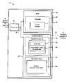
- FIG. 4 is a block diagram of the disk adapter (from FIG. 2 ) having a local memory for storing firmware processes, in particular, a cache manager, a local copy of one or more extents, and other information.
- FIG. 5A is an exemplary format of the extent control data structure (from FIG. 4 ) to store values of extent control data for an associated local extent at a selected level of re-use.
- FIG. 5B is a table of exemplary extent control parameters for different levels of local extent re-use.
- FIG. 6 is a flow diagram depicting a cache slot replacement process of the cache manager.
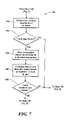
- FIG. 7 is a flow diagram depicting operation of a local extent re-use determination portion of the cache slot replacement process.
- FIG. 8 is a flow diagram depicting an automatic DMA mechanism to access an extent in the global memory.
- a data processing system 10 includes a plurality of host computers 12 a , 12 b , . . . , 12 m , connected to a data storage system 14 .
- the data storage system 14 can be, for example, that made by EMC Corporation and known as the Symmetrix® data storage system.
- the data storage system 14 receives data and commands from, and delivers data and responses to, the host computers 12 .
- the data storage system 14 is a mass storage system having a controller 16 coupled to pluralities of physical storage devices (or, simply, physical devices) shown as physical disks 18 a , physical disks 18 b , . . . , physical disks 18 k .
- Each of the physical devices 18 is logically divided, in accordance with known techniques, into one or more logical volumes.
- the controller 16 interconnects the host computers 12 and the physical devices 18 .
- the controller 16 thus receives memory write commands from the various host computers over buses 20 a , 20 b , . . . , 20 m , respectively, and delivers the data associated with those commands to the appropriate physical devices 18 a , 18 b , . . . , 18 k , over respective connecting buses 22 a , 22 b , . . . , 22 k .
- the controller 16 also receives read requests from the host computers 12 over buses 20 , and delivers requested data to the host computers 12 , either from a cache memory of the controller 16 or, if the data is not available in cache memory, from the physical devices 18 .
- Buses 20 can be operated in accordance with any one of a number of different bus protocols, such as Fibre Channel, SCSI, FICON and ESCON, to name but a few.
- buses 22 can also be operated in accordance with any one of a number of different bus protocols, for example, Fibre Channel, SCSI and Serial ATA, as well as others.
- the controller 16 also connects to a console PC 24 through a connecting bus 26 .
- Console PC 24 is used for maintenance and access to the controller 16 and can be employed to set parameters of the controller 16 as is well known in the art.
- the host computers 12 a , 12 b , . . . send, as required by the applications they are running, commands to the data storage system 14 requesting data stored in the logical volumes or providing data to be written to the logical volumes.
- FIG. 2 and using the controller in the Symmetrix® data storage system as an illustrative example, details of the internal architecture of the data storage system 14 are shown.
- the communications from the host computer 12 typically connects to a port of a plurality of host adapters 30 over the bus lines 20 .
- Each host adapter connects to a global memory 36 via an interconnect 32 .
- the interconnect can be, for example, a bus structure, a point-to-point interconnect such as a crossbar structure, or any other type of interconnect.
- the global memory 36 includes a cache memory 38 for storing cached data and control data structures, as will be described.
- the control data structures include is a cache index/directory for mapping areas of the disk devices 18 to areas in the cache memory 38 .
- disk adapters 44 Also connected to the global memory 36 through the interconnect 32 are device adapters shown as disk adapters 44 , which control the physical devices 18 and handle the controller's back-end operations.
- the host adapters 30 can communicate with the disk adapters 44 through either the global memory 36 or some other messaging scheme.
- the disk adapters are installed in controller 16 in pairs. Thus, for simplification, only two disk adapters, indicated as disk adapters 44 a and 44 b , are shown. However, it will be understood that additional disk adapters may be employed by the system.
- Each of the disk adapters 44 a , 44 b supports multiple bus ports, as shown.
- the disk adapter (DA) 44 a connects to buses 22 a and 22 b
- DA 44 b connects to buses 22 c and 22 d .
- Each DA can support additional buses as well.
- Connected to buses 22 a and 22 b are a plurality of physical devices (shown as disk drive units) 18 a and 18 b , respectively.
- Connected to the buses 22 c , 22 d are the plurality of physical devices 18 c and 18 d , respectively.
- the DAs 44 , buses 22 and devices 18 may be configured in such a way as to support redundancy, e.g., the devices 18 on the buses 22 can include both primary and secondary devices.
- the cache memory 38 operates as a cache buffer in connection with storage and retrieval operations, in particular caching update information provided by the host adapter 30 during a storage operation and information received from the storage devices 18 which may be retrieved by the host adapter 30 during a retrieval operation.
- the cache memory 38 includes a plurality of storage locations, which are organized in a series of cache slots.
- the cache memory 38 includes one or more units of cache referred to as cache slots banks 50 , shown as cache slots banks 50 a , 50 b , . . . , 50 n .
- a cache slots bank is the smallest unit of cache that can be logically disabled.
- Each bank 50 is divided into one or more cache slots 52 , and a control slot 54 .
- the control slot 54 usually much smaller than the cache slots, stores control information associated with the cache slots of the bank to which that control slot belongs.
- each cache slot 52 includes a header portion and a data portion that contains information that is cached in the cache slot for a data element, typically a track, with which the cache slot is associated, i.e., a track identified by the header.
- the header may include such information as slot address, write pending (WP) flag, track ID, pointer and other status and control information.
- a cache index/directory operates as an index for the cache slots in the cache memory 38 . It includes a cache index table for each of the storage devices 18 a , 18 b , . . . , 18 k , in the data storage system 12 . Each cache index table includes device header information, for example, selected identification and status information for the storage device 18 associated with the table. In addition, each cache index table includes cylinder descriptors and each cylinder descriptor includes track descriptors for each track in the cylinder. Each track descriptor includes information for the associated track of the storage device, including whether the track is associated with a cache slot, and, if so, an identification of the cache slot with which the track is associated.
- each track descriptor includes a “cached” flag and a cache slot pointer.
- the cached flag if set, indicates that the track associated with the track descriptor is associated with a cache slot. If the cached flag is set, the cache slot pointer points to one of the cache slots, thereby associating the track with the respective cache slot. If the cached flag is set, information from the track is cached in the cache slot identified by the cache slot pointer for retrieval by one or more of the host directors 20 . As described above, and referring back to FIGS.
- the host adapter 30 typically performs storage (or write) and retrieval (or read) operations in connection with information that has been cached in the cache memory 40
- the disk adapters 44 performs operations to transfer information in the storage devices 18 to the cache memory 38 for buffering (“staging”) and to transfer information from the cache memory 38 to the storage devices 18 for storage (“destaging”).
- the host adapter 30 attempts to retrieve the information for a particular track from the cache memory 38 . However, if the condition of the cached flag associated with that track indicates that the information is not in the cache memory 38 (in other words, a cache miss has occurred), it will enable the disk adapter 44 which controls the storage device 18 that contains the information to retrieve the information from the track which contains it and transfer the information into a cache slot in the cache memory 38 . Once the disk adapter 44 has performed this operation, it updates the directory to indicate that the information from the track resides in a cache slot in the cache memory 38 , in particular, setting a corresponding cached flag and loading a pointer to the cache slot in the cache slot pointer.
- the disk adapter 44 After the disk adapter 44 has stored the data in the cache memory 38 , it notifies the host director 30 that the requested data is available. At some point after receiving the notification, the host adapter 30 uses the tables of the directory to identify the appropriate cache slot and retrieves the requested data from that cache slot.
- the host adapter 30 determines if information from a track to be written is cached in a cache slot. If cached, the host adapter updates the cache slot with new data. If the host adapter 30 determines that the track is not associated with a cache slot, it selects a cache slot, stores the new data in the selected cache slot and updates the track descriptor. Once the new data is stored in the cache slot, the host adapter 30 notifies the disk adapter 44 so that the disk adapter 44 can write the data cached in the cache slot to the track and storage device with which the cache slot is associated as part of a destaging operation.
- a cache index/directory provides an indication of the data, which is stored in the cache memory 38 and provides the addresses of the data stored in the cache memory 38 .
- the cache index/directory can be organized as a hierarchy of tables for devices (logical volumes), cylinders and tracks, as described in Yanai et al., U.S. Pat. No. 5,206,939, and Vishlitzky et al., U.S. Pat. No. 6,049,850, both of which are incorporated herein by reference.
- the control data structures associated with the cached data in the cache memory 38 might include a cache slots Least Recently Used (LRU) data structure and global memory Write Pending data structures.
- LRU Least Recently Used
- One global memory write pending data structure would be maintained for each logical volume residing on the data storage system 14 .
- the cache slots LRU data structure would includes a list of cache slots in the cache memory 38 , as well as a head pointer to point to the head of the list and a tail pointer to point to the tail of the list.
- Such a cache slots LRU data structure would be used by the adapters 30 , 44 for readily identifying the least-recently-used cache slot or data element in the cache memory 38 .
- the cache slots LRU data structure could be a conventional LRU queue, or a “replacement queue” as described in Vishlitzky et al. U.S. Pat. No. 5,706,467.
- the corresponding host adapter 30 updates the cache index/directory as necessary to indicate a write pending in the appropriate tables and, if a write pending is not already indicated, removes the cache slot or slots containing the modified data from the LRU data structure (so that they will not be overwritten before destaging can occur) as necessary.
- the use of a conventional LRU queue requires many pointer updates and accesses to the global memory 36 .
- the control slot 54 in each cache slots bank 50 includes one or more tables (referred to hereinafter as “extents”) for cache slot replacement management.
- the disk adapter 44 is configured to support use of the extents in such a way that reduces global memory access operations (while taking into account the desirability for distribution of slots across different extents).
- each extent 56 stores a plurality of entries, each entry comprising a tag 60 corresponding to a cache slot 52 in the cache slots bank 50 to which the extent belongs.
- the tag 60 includes a cache slot protection bit or (“L” bit) 62 , which when set indicates that the corresponding cache slot is vulnerable (for example, it is a write pending cache slot), and should not be selected during cache slot replacement for new data.
- L cache slot protection bit
- a tag with a “0” in the timestamp is indicative of invalid or “junk” data (e.g., as might be the case if the tag is associated with a cache slot used by the disk adapter to store scratch data) is the “best candidate” for a new slot.
- the next “best candidate” is a tag in which the “L” bit is “0” and has the oldest timestamp.
- the extent 56 thus behaves like a perfect LRU. It can be read in one operation, and requires only one global memory compare/swap for updates (in cases of cache hits and new cache slot assignments). Although the performance of the extent in global memory 36 is superior in many respects to that of conventional LRU data structures, the extent 56 in global memory still requires that the disk adapter 44 perform an external memory access to the global memory 36 , which can be a slow operation. To address this problem, as noted earlier, the disk adapter 44 is configured to store a local copy of a requested extent (“local extent” or “locally buffered extent”). Thus, the DA 44 , when it requires a new cache slot in response to a host request, copies an extent from global memory into a local buffer.
- the DA 44 can determine if the locally buffered extent can be re-used, or if it is necessary to copy the next extent from global memory.
- the DA 44 also supports various levels of local extent re-usability desired by a user, as will be described.
- the disk adapter 44 includes at least one processor 80 coupled to local memory including a control store 82 and a local, nonvolatile memory (NVM) 84 by an internal bus 86 .
- the processor 80 controls the overall operations of the disk adapter 44 and communications with the memories 82 and 84 .
- the local memory 84 stores firmware (or microcode) 88 , including a cache manager 90 .
- the cache manager 90 has routines for accessing cache slots in the global memory 36 .
- the local volatile memory 82 stores control data structures 92 and parameter data in a parameter store 94 .
- the firmware 88 and parameter store 94 are read each time the data storage system 14 is initialized.
- the firmware 88 is copied into the control store 82 (or the processor's internal RAM) at initialization for subsequent execution by the processor 80 .
- control data structures 92 will include at least one locally buffered extent 96 as well as associated extent control data 98 .
- the parameters stored in the parameter store 94 include, among other information, extent control parameters 100 which specify conditions under which re-use of a locally buffered extent 96 is permitted.
- the extent control data 98 is statistical data that is collected for the locally buffered (or local) extent over time and measured against the extent control parameters when the possible re-use of the local extent is considered during a new slot allocation activity. It will be appreciated that more than more than one extent may be buffered locally.
- an exemplary format of the extent control data 98 collected in association with a locally buffered extent 96 include the following: an extent re-use level 110 ; a last read value (in microseconds) 112 ; a removed age 114 ; a maximum usage value 116 ; and available slots counts 118 , 120 and 122 .
- the level 110 corresponds to a user-configurable extent re-use level.
- the last read value 112 indicates the time (in microseconds) since the locally buffered extent was last read.
- the removed age 114 is the minimum age of the last removed cache slot (expressed in terms of an average fall through time (“ftt”) approximation).
- the maximum usage value 116 provides the number of times the locally buffered extent can be reused.
- the available slots counts indicate the number of available slots (L-bit not set) in the locally buffered extent the first time it is used 118 , the second time it is used 120 (first re-use) and the third time it is used 122 (second re-use), respectively.
- the second re-use is possible only in FBA machines, because CKD extents have only 188 tags.
- FIG. 5B shows exemplary parameter values for parameters corresponding to the data shown in FIG. 5A .
- four levels 0 through 3 130 are supports.
- Level 0, at one end of the range of levels, is the most restrictive, while level 3 at the opposite end is the most relaxed.
- Level 3 is quite generous about the amount of time since the locally buffered extent was last read, as well as the maximum slot usage, as this level allows up to 8 slots from one extent.
- a user can optimize performance or adjust the level of re-use of the local extent as appropriate for the type of operation or application to be performed. For example, for usage patterns exhibiting a very low cache hit ratio, it may be desirable to select a level 0 or 1. As well, those levels are likely to be used under circumstances in which the DA has to be selective about which slots to use. On the other hand, a level 3 may be desirable during instances in which caching offers little benefit, for example, during a backup (recovery) process. The use of level 3 during such activity would allow the process to obtain cache slots quickly.
- the DAs 44 or even processors 80 in a given DA may be configured differently, that is, with different extent re-use levels and/or other extent control parameters.
- the values in the table of FIG. 100 are merely an example of possible settings for the different levels to achieve varying degrees of extent re-use. Other parameter values may be chosen. A different number of levels could be used as well.
- a user can set the level and adjust any of the associated parameters using a host-based interface or a separate management tool that may reside on the host or some other system that can communicated with the controller 16 .
- the settings can be set or modified via an in-line interface of PC 24 . Any of these types of interfaces would allow a system call to be made to the controller 16 to change the extent control parameters.
- a user has the capability to disable the feature as well.
- the process 90 begins (step 140 ) with a request for a new cache slot (step 142 ). Thus, the process 90 needs to perform an extent lookup to find a cache slot to be used.
- the process 90 first determines if the re-use of a locally buffered extent is an option (step 144 ). If it is, the process 90 examines a locally buffered extent to find a best candidate for slot replacement (step 146 ).
- step 148 the process 90 updates the extent and associated extent control data (as well as updates the corresponding global memory extent and cache slots in the case of new writes and read misses)(step 149 ), and then terminates (step 150 ) upon completion of extent access and compare/swap activities.
- the search may be unsuccessful. For example, all of the tags in the extent may indicate vulnerable slots (such as write pending slots), or there may be a mismatch between the selected “best candidate” tag in local memory and global memory (which would be the case if another DA had updated the tag since the extent was copied to local memory). If it is determined that the search failed (at step 148 ), or it is determined at step 144 that the local extent cannot be re-used, the process 90 copies the next extent from global memory into the local memory (step 152 ) and proceeds to the step of searching the local copy of the extent for a best candidate.
- the process 90 checks the local buffer(s) in the local memory for an extent (step 160 ). If a local copy of an extent is not found (step 162 ), the process 90 proceeds to step 152 ( FIG. 6 ). If a locally buffered extent is available, the process 90 reads the associated extent control data for that extent (step 164 ) and compares the data with the extent control parameters for the “re-use” level in use (step 166 ). The results are used to determine if re-use of the local extent is allowed (step 168 ).
- step 146 search for the best candidate (for slot replacement) and perform the update activities of step 149 if the search yields a best candidate. Otherwise, if extent re-use is not allowed for the selected extent, the process 90 may access another locally buffered extent (and thus repeat step 144 ), or return to step 152 ( FIG. 6 ) to obtain the next extent from global memory.
- the DA 44 can use an automatic DMA (“auto-DMA”) mechanism 170 to copy extents from global memory to local memory.
- auto-DMA automatic DMA
- one of the processors is dedicated to accessing global memory and executes the auto-DMA process.
- the auto-DMA process 170 assumes the availability of at least one additional local buffer in the DA 44 .
- the auto-DMA mechanism maintains various control information to distinguish between a current buffer that has been filled by the last auto-DMA operation and may be ready for use, and the other buffer (in the case of two buffers) that is being filled by a current auto-DMA operation for future use.
- An “actual hand” points to the current extent (for, example, using a value corresponding to the control slot pointer plus an index or offset value of the extent) stored in the current buffer.
- a “predicted hand” is used to indicate (or predict) the next extent to be used, that is, once the current auto-DMA operation is completed.
- a stamp which includes a time stamp, including a macro-timer value and a micro-timer value, as well as a unique identifier (ID) of the request.
- the process begins (step 171 ) with a DA processor auto-DMA request.
- the process 170 sets a “current buffer” pointer to the other buffer (step 172 ) and advances the actual hand (step 174 ) to the next extent.
- the process determines if the buffer data is still valid, first by checking the stamp to determine if the last auto-DMA operation was recent enough (for example, was the macro-timer value within a timeframe, such as a 0.5 s window, and was the micro-timer within a finer window of, say, 10 or 100 ms).
Abstract
Description
Claims (12)
Priority Applications (1)
| Application Number | Priority Date | Filing Date | Title |
|---|---|---|---|
| US10/667,564 US7089357B1 (en) | 2003-09-22 | 2003-09-22 | Locally buffered cache extensions having associated control parameters to determine use for cache allocation on subsequent requests |
Applications Claiming Priority (1)
| Application Number | Priority Date | Filing Date | Title |
|---|---|---|---|
| US10/667,564 US7089357B1 (en) | 2003-09-22 | 2003-09-22 | Locally buffered cache extensions having associated control parameters to determine use for cache allocation on subsequent requests |
Publications (1)
| Publication Number | Publication Date |
|---|---|
| US7089357B1 true US7089357B1 (en) | 2006-08-08 |
Family
ID=36942134
Family Applications (1)
| Application Number | Title | Priority Date | Filing Date |
|---|---|---|---|
| US10/667,564 Active 2024-08-16 US7089357B1 (en) | 2003-09-22 | 2003-09-22 | Locally buffered cache extensions having associated control parameters to determine use for cache allocation on subsequent requests |
Country Status (1)
| Country | Link |
|---|---|
| US (1) | US7089357B1 (en) |
Cited By (5)
| Publication number | Priority date | Publication date | Assignee | Title |
|---|---|---|---|---|
| US20050240727A1 (en) * | 2004-04-23 | 2005-10-27 | Shishir Shah | Method and system for managing storage area networks |
| US20050273672A1 (en) * | 2004-05-18 | 2005-12-08 | Konda Dharma R | Method and system for efficiently recording processor events in host bus adapters |
| US20060112368A1 (en) * | 2004-11-12 | 2006-05-25 | International Business Machines Corporation | System and method for managing position independent code using a software framework |
| US20120117328A1 (en) * | 2010-11-04 | 2012-05-10 | Lsi Corporation | Managing a Storage Cache Utilizing Externally Assigned Cache Priority Tags |
| US8850114B2 (en) | 2010-09-07 | 2014-09-30 | Daniel L Rosenband | Storage array controller for flash-based storage devices |
Citations (19)
| Publication number | Priority date | Publication date | Assignee | Title |
|---|---|---|---|---|
| US5768623A (en) * | 1995-09-19 | 1998-06-16 | International Business Machines Corporation | System and method for sharing multiple storage arrays by dedicating adapters as primary controller and secondary controller for arrays reside in different host computers |
| US6029229A (en) | 1997-01-29 | 2000-02-22 | Emc Corporation | Digital data storage subsystem including directory for efficiently providing formatting information for stored records |
| US6047353A (en) | 1997-05-07 | 2000-04-04 | Emc Corporation | Method and apparatus for monitoring of host activities relating to an attached storage device |
| US6457102B1 (en) | 1999-11-05 | 2002-09-24 | Emc Corporation | Cache using multiple LRU's |
| US6487635B1 (en) | 2000-11-29 | 2002-11-26 | Emc Corporation | Management of orphan tracks |
| US20030005234A1 (en) * | 2001-06-29 | 2003-01-02 | Zeev Sperber | System and method for optimizing bus bandwidth utilization by reducing read to write bubbles |
| US20030023808A1 (en) * | 2001-07-26 | 2003-01-30 | Bakke Brian Eric | Method and system for maintaining data coherency in a dual input/output adapter utilizing clustered adapters |
| US6581143B2 (en) * | 1999-12-23 | 2003-06-17 | Emc Corporation | Data processing method and apparatus for enabling independent access to replicated data |
| US6640285B1 (en) | 2000-10-26 | 2003-10-28 | Emc Corporation | Method and apparatus for improving the efficiency of cache memories using stored activity measures |
| US6643667B1 (en) * | 1999-03-19 | 2003-11-04 | Hitachi, Ltd. | System and method for replicating data |
| US6654855B1 (en) | 2000-10-26 | 2003-11-25 | Emc Corporation | Method and apparatus for improving the efficiency of cache memories using chained metrics |
| US20030229764A1 (en) * | 2002-06-05 | 2003-12-11 | Hitachi, Ltd. | Data storage subsystem |
| US6715039B1 (en) | 2001-09-12 | 2004-03-30 | Emc Corporation | Cache slot promotion in a replacement queue cache using determinations of probabilities and costs |
| US6725331B1 (en) | 1998-01-07 | 2004-04-20 | Emc Corporation | Method and apparatus for managing the dynamic assignment resources in a data storage system |
| US6742138B1 (en) * | 2001-06-12 | 2004-05-25 | Emc Corporation | Data recovery method and apparatus |
| US6754897B1 (en) | 1999-11-12 | 2004-06-22 | Emc Corporation | Operation prioritization and selection in a probability-based job scheduler |
| US6757790B2 (en) | 2002-02-19 | 2004-06-29 | Emc Corporation | Distributed, scalable data storage facility with cache memory |
| US20040128456A1 (en) * | 2002-12-26 | 2004-07-01 | Hitachi, Ltd. | Storage system and data backup method for the same |
| US6807619B1 (en) | 2002-02-21 | 2004-10-19 | Emc Corporation | Advancing bank pointer in prime numbers unit |
-
2003
- 2003-09-22 US US10/667,564 patent/US7089357B1/en active Active
Patent Citations (21)
| Publication number | Priority date | Publication date | Assignee | Title |
|---|---|---|---|---|
| US5768623A (en) * | 1995-09-19 | 1998-06-16 | International Business Machines Corporation | System and method for sharing multiple storage arrays by dedicating adapters as primary controller and secondary controller for arrays reside in different host computers |
| US6029229A (en) | 1997-01-29 | 2000-02-22 | Emc Corporation | Digital data storage subsystem including directory for efficiently providing formatting information for stored records |
| US6047353A (en) | 1997-05-07 | 2000-04-04 | Emc Corporation | Method and apparatus for monitoring of host activities relating to an attached storage device |
| US6725331B1 (en) | 1998-01-07 | 2004-04-20 | Emc Corporation | Method and apparatus for managing the dynamic assignment resources in a data storage system |
| US6643667B1 (en) * | 1999-03-19 | 2003-11-04 | Hitachi, Ltd. | System and method for replicating data |
| US6728836B1 (en) | 1999-11-05 | 2004-04-27 | Emc Corporation | Segmenting cache to provide varying service levels |
| US6457102B1 (en) | 1999-11-05 | 2002-09-24 | Emc Corporation | Cache using multiple LRU's |
| US6754897B1 (en) | 1999-11-12 | 2004-06-22 | Emc Corporation | Operation prioritization and selection in a probability-based job scheduler |
| US6581143B2 (en) * | 1999-12-23 | 2003-06-17 | Emc Corporation | Data processing method and apparatus for enabling independent access to replicated data |
| US6640285B1 (en) | 2000-10-26 | 2003-10-28 | Emc Corporation | Method and apparatus for improving the efficiency of cache memories using stored activity measures |
| US6654855B1 (en) | 2000-10-26 | 2003-11-25 | Emc Corporation | Method and apparatus for improving the efficiency of cache memories using chained metrics |
| US6487635B1 (en) | 2000-11-29 | 2002-11-26 | Emc Corporation | Management of orphan tracks |
| US6742138B1 (en) * | 2001-06-12 | 2004-05-25 | Emc Corporation | Data recovery method and apparatus |
| US20030005234A1 (en) * | 2001-06-29 | 2003-01-02 | Zeev Sperber | System and method for optimizing bus bandwidth utilization by reducing read to write bubbles |
| US20030023808A1 (en) * | 2001-07-26 | 2003-01-30 | Bakke Brian Eric | Method and system for maintaining data coherency in a dual input/output adapter utilizing clustered adapters |
| US6530003B2 (en) * | 2001-07-26 | 2003-03-04 | International Business Machines Corporation | Method and system for maintaining data coherency in a dual input/output adapter utilizing clustered adapters |
| US6715039B1 (en) | 2001-09-12 | 2004-03-30 | Emc Corporation | Cache slot promotion in a replacement queue cache using determinations of probabilities and costs |
| US6757790B2 (en) | 2002-02-19 | 2004-06-29 | Emc Corporation | Distributed, scalable data storage facility with cache memory |
| US6807619B1 (en) | 2002-02-21 | 2004-10-19 | Emc Corporation | Advancing bank pointer in prime numbers unit |
| US20030229764A1 (en) * | 2002-06-05 | 2003-12-11 | Hitachi, Ltd. | Data storage subsystem |
| US20040128456A1 (en) * | 2002-12-26 | 2004-07-01 | Hitachi, Ltd. | Storage system and data backup method for the same |
Cited By (8)
| Publication number | Priority date | Publication date | Assignee | Title |
|---|---|---|---|---|
| US20050240727A1 (en) * | 2004-04-23 | 2005-10-27 | Shishir Shah | Method and system for managing storage area networks |
| US20050273672A1 (en) * | 2004-05-18 | 2005-12-08 | Konda Dharma R | Method and system for efficiently recording processor events in host bus adapters |
| US7669190B2 (en) * | 2004-05-18 | 2010-02-23 | Qlogic, Corporation | Method and system for efficiently recording processor events in host bus adapters |
| US20060112368A1 (en) * | 2004-11-12 | 2006-05-25 | International Business Machines Corporation | System and method for managing position independent code using a software framework |
| US7512699B2 (en) * | 2004-11-12 | 2009-03-31 | International Business Machines Corporation | Managing position independent code using a software framework |
| US8850114B2 (en) | 2010-09-07 | 2014-09-30 | Daniel L Rosenband | Storage array controller for flash-based storage devices |
| US20120117328A1 (en) * | 2010-11-04 | 2012-05-10 | Lsi Corporation | Managing a Storage Cache Utilizing Externally Assigned Cache Priority Tags |
| US8595451B2 (en) * | 2010-11-04 | 2013-11-26 | Lsi Corporation | Managing a storage cache utilizing externally assigned cache priority tags |
Similar Documents
| Publication | Publication Date | Title |
|---|---|---|
| US4875155A (en) | Peripheral subsystem having read/write cache with record access | |
| US7437515B1 (en) | Data structure for write pending | |
| CN110998557B (en) | High availability database system and method via distributed storage | |
| US7380059B2 (en) | Methods and systems of cache memory management and snapshot operations | |
| US7117310B2 (en) | Systems and methods for cache synchronization between redundant storage controllers | |
| US9280478B2 (en) | Cache rebuilds based on tracking data for cache entries | |
| US7177853B1 (en) | Cache management via statistically adjusted time stamp queue | |
| EP0062175B1 (en) | Data processing apparatus with early cache discard | |
| US7849254B2 (en) | Create virtual track buffers in NVS using customer segments to maintain newly written data across a power loss | |
| US6877065B2 (en) | Advanced read cache management | |
| US7249218B2 (en) | Method, system, and program for managing an out of available space condition | |
| US8966155B1 (en) | System and method for implementing a high performance data storage system | |
| US7558919B1 (en) | Dynamic cache partitioning | |
| US8667224B1 (en) | Techniques for data prefetching | |
| AU1578092A (en) | Cache memory system and method of operating the cache memory system | |
| US5590300A (en) | Cache memory utilizing address translation table | |
| JPH0458051B2 (en) | ||
| US7743209B2 (en) | Storage system for virtualizing control memory | |
| US6286080B1 (en) | Advanced read cache emulation | |
| US7552282B1 (en) | Method, computer readable medium, and data storage system for selective data replication of cached data | |
| US20140344510A1 (en) | Storage system | |
| US5694570A (en) | Method and system of buffering data written to direct access storage devices in data processing systems | |
| US8082397B1 (en) | Private slot | |
| US6782444B1 (en) | Digital data storage subsystem including directory for efficiently providing formatting information for stored records | |
| US7822923B2 (en) | Storage control program, storage control apparatus, and storage control method |
Legal Events
| Date | Code | Title | Description |
|---|---|---|---|
| AS | Assignment |
Owner name: EMC CORPORATION, MASSACHUSETTS Free format text: ASSIGNMENT OF ASSIGNORS INTEREST;ASSIGNOR:EZRA, JOSEF;REEL/FRAME:014561/0851 Effective date: 20030915 |
|
| STCF | Information on status: patent grant |
Free format text: PATENTED CASE |
|
| CC | Certificate of correction | ||
| FPAY | Fee payment |
Year of fee payment: 4 |
|
| FPAY | Fee payment |
Year of fee payment: 8 |
|
| AS | Assignment |
Owner name: THE BANK OF NEW YORK MELLON TRUST COMPANY, N.A., AS NOTES COLLATERAL AGENT, TEXAS Free format text: SECURITY AGREEMENT;ASSIGNORS:ASAP SOFTWARE EXPRESS, INC.;AVENTAIL LLC;CREDANT TECHNOLOGIES, INC.;AND OTHERS;REEL/FRAME:040136/0001 Effective date: 20160907 Owner name: CREDIT SUISSE AG, CAYMAN ISLANDS BRANCH, AS COLLATERAL AGENT, NORTH CAROLINA Free format text: SECURITY AGREEMENT;ASSIGNORS:ASAP SOFTWARE EXPRESS, INC.;AVENTAIL LLC;CREDANT TECHNOLOGIES, INC.;AND OTHERS;REEL/FRAME:040134/0001 Effective date: 20160907 Owner name: CREDIT SUISSE AG, CAYMAN ISLANDS BRANCH, AS COLLAT Free format text: SECURITY AGREEMENT;ASSIGNORS:ASAP SOFTWARE EXPRESS, INC.;AVENTAIL LLC;CREDANT TECHNOLOGIES, INC.;AND OTHERS;REEL/FRAME:040134/0001 Effective date: 20160907 Owner name: THE BANK OF NEW YORK MELLON TRUST COMPANY, N.A., A Free format text: SECURITY AGREEMENT;ASSIGNORS:ASAP SOFTWARE EXPRESS, INC.;AVENTAIL LLC;CREDANT TECHNOLOGIES, INC.;AND OTHERS;REEL/FRAME:040136/0001 Effective date: 20160907 |
|
| AS | Assignment |
Owner name: EMC IP HOLDING COMPANY LLC, MASSACHUSETTS Free format text: ASSIGNMENT OF ASSIGNORS INTEREST;ASSIGNOR:EMC CORPORATION;REEL/FRAME:040203/0001 Effective date: 20160906 |
|
| MAFP | Maintenance fee payment |
Free format text: PAYMENT OF MAINTENANCE FEE, 12TH YEAR, LARGE ENTITY (ORIGINAL EVENT CODE: M1553) Year of fee payment: 12 |
|
| AS | Assignment |
Owner name: THE BANK OF NEW YORK MELLON TRUST COMPANY, N.A., T Free format text: SECURITY AGREEMENT;ASSIGNORS:CREDANT TECHNOLOGIES, INC.;DELL INTERNATIONAL L.L.C.;DELL MARKETING L.P.;AND OTHERS;REEL/FRAME:049452/0223 Effective date: 20190320 Owner name: THE BANK OF NEW YORK MELLON TRUST COMPANY, N.A., TEXAS Free format text: SECURITY AGREEMENT;ASSIGNORS:CREDANT TECHNOLOGIES, INC.;DELL INTERNATIONAL L.L.C.;DELL MARKETING L.P.;AND OTHERS;REEL/FRAME:049452/0223 Effective date: 20190320 |
|
| AS | Assignment |
Owner name: THE BANK OF NEW YORK MELLON TRUST COMPANY, N.A., TEXAS Free format text: SECURITY AGREEMENT;ASSIGNORS:CREDANT TECHNOLOGIES INC.;DELL INTERNATIONAL L.L.C.;DELL MARKETING L.P.;AND OTHERS;REEL/FRAME:053546/0001 Effective date: 20200409 |
|
| AS | Assignment |
Owner name: WYSE TECHNOLOGY L.L.C., CALIFORNIA Free format text: RELEASE BY SECURED PARTY;ASSIGNOR:CREDIT SUISSE AG, CAYMAN ISLANDS BRANCH;REEL/FRAME:058216/0001 Effective date: 20211101 Owner name: SCALEIO LLC, MASSACHUSETTS Free format text: RELEASE BY SECURED PARTY;ASSIGNOR:CREDIT SUISSE AG, CAYMAN ISLANDS BRANCH;REEL/FRAME:058216/0001 Effective date: 20211101 Owner name: MOZY, INC., WASHINGTON Free format text: RELEASE BY SECURED PARTY;ASSIGNOR:CREDIT SUISSE AG, CAYMAN ISLANDS BRANCH;REEL/FRAME:058216/0001 Effective date: 20211101 Owner name: MAGINATICS LLC, CALIFORNIA Free format text: RELEASE BY SECURED PARTY;ASSIGNOR:CREDIT SUISSE AG, CAYMAN ISLANDS BRANCH;REEL/FRAME:058216/0001 Effective date: 20211101 Owner name: FORCE10 NETWORKS, INC., CALIFORNIA Free format text: RELEASE BY SECURED PARTY;ASSIGNOR:CREDIT SUISSE AG, CAYMAN ISLANDS BRANCH;REEL/FRAME:058216/0001 Effective date: 20211101 Owner name: EMC IP HOLDING COMPANY LLC, TEXAS Free format text: RELEASE BY SECURED PARTY;ASSIGNOR:CREDIT SUISSE AG, CAYMAN ISLANDS BRANCH;REEL/FRAME:058216/0001 Effective date: 20211101 Owner name: EMC CORPORATION, MASSACHUSETTS Free format text: RELEASE BY SECURED PARTY;ASSIGNOR:CREDIT SUISSE AG, CAYMAN ISLANDS BRANCH;REEL/FRAME:058216/0001 Effective date: 20211101 Owner name: DELL SYSTEMS CORPORATION, TEXAS Free format text: RELEASE BY SECURED PARTY;ASSIGNOR:CREDIT SUISSE AG, CAYMAN ISLANDS BRANCH;REEL/FRAME:058216/0001 Effective date: 20211101 Owner name: DELL SOFTWARE INC., CALIFORNIA Free format text: RELEASE BY SECURED PARTY;ASSIGNOR:CREDIT SUISSE AG, CAYMAN ISLANDS BRANCH;REEL/FRAME:058216/0001 Effective date: 20211101 Owner name: DELL PRODUCTS L.P., TEXAS Free format text: RELEASE BY SECURED PARTY;ASSIGNOR:CREDIT SUISSE AG, CAYMAN ISLANDS BRANCH;REEL/FRAME:058216/0001 Effective date: 20211101 Owner name: DELL MARKETING L.P., TEXAS Free format text: RELEASE BY SECURED PARTY;ASSIGNOR:CREDIT SUISSE AG, CAYMAN ISLANDS BRANCH;REEL/FRAME:058216/0001 Effective date: 20211101 Owner name: DELL INTERNATIONAL, L.L.C., TEXAS Free format text: RELEASE BY SECURED PARTY;ASSIGNOR:CREDIT SUISSE AG, CAYMAN ISLANDS BRANCH;REEL/FRAME:058216/0001 Effective date: 20211101 Owner name: DELL USA L.P., TEXAS Free format text: RELEASE BY SECURED PARTY;ASSIGNOR:CREDIT SUISSE AG, CAYMAN ISLANDS BRANCH;REEL/FRAME:058216/0001 Effective date: 20211101 Owner name: CREDANT TECHNOLOGIES, INC., TEXAS Free format text: RELEASE BY SECURED PARTY;ASSIGNOR:CREDIT SUISSE AG, CAYMAN ISLANDS BRANCH;REEL/FRAME:058216/0001 Effective date: 20211101 Owner name: AVENTAIL LLC, CALIFORNIA Free format text: RELEASE BY SECURED PARTY;ASSIGNOR:CREDIT SUISSE AG, CAYMAN ISLANDS BRANCH;REEL/FRAME:058216/0001 Effective date: 20211101 Owner name: ASAP SOFTWARE EXPRESS, INC., ILLINOIS Free format text: RELEASE BY SECURED PARTY;ASSIGNOR:CREDIT SUISSE AG, CAYMAN ISLANDS BRANCH;REEL/FRAME:058216/0001 Effective date: 20211101 |
|
| AS | Assignment |
Owner name: SCALEIO LLC, MASSACHUSETTS Free format text: RELEASE OF SECURITY INTEREST IN PATENTS PREVIOUSLY RECORDED AT REEL/FRAME (040136/0001);ASSIGNOR:THE BANK OF NEW YORK MELLON TRUST COMPANY, N.A., AS NOTES COLLATERAL AGENT;REEL/FRAME:061324/0001 Effective date: 20220329 Owner name: EMC IP HOLDING COMPANY LLC (ON BEHALF OF ITSELF AND AS SUCCESSOR-IN-INTEREST TO MOZY, INC.), TEXAS Free format text: RELEASE OF SECURITY INTEREST IN PATENTS PREVIOUSLY RECORDED AT REEL/FRAME (040136/0001);ASSIGNOR:THE BANK OF NEW YORK MELLON TRUST COMPANY, N.A., AS NOTES COLLATERAL AGENT;REEL/FRAME:061324/0001 Effective date: 20220329 Owner name: EMC CORPORATION (ON BEHALF OF ITSELF AND AS SUCCESSOR-IN-INTEREST TO MAGINATICS LLC), MASSACHUSETTS Free format text: RELEASE OF SECURITY INTEREST IN PATENTS PREVIOUSLY RECORDED AT REEL/FRAME (040136/0001);ASSIGNOR:THE BANK OF NEW YORK MELLON TRUST COMPANY, N.A., AS NOTES COLLATERAL AGENT;REEL/FRAME:061324/0001 Effective date: 20220329 Owner name: DELL MARKETING CORPORATION (SUCCESSOR-IN-INTEREST TO FORCE10 NETWORKS, INC. AND WYSE TECHNOLOGY L.L.C.), TEXAS Free format text: RELEASE OF SECURITY INTEREST IN PATENTS PREVIOUSLY RECORDED AT REEL/FRAME (040136/0001);ASSIGNOR:THE BANK OF NEW YORK MELLON TRUST COMPANY, N.A., AS NOTES COLLATERAL AGENT;REEL/FRAME:061324/0001 Effective date: 20220329 Owner name: DELL PRODUCTS L.P., TEXAS Free format text: RELEASE OF SECURITY INTEREST IN PATENTS PREVIOUSLY RECORDED AT REEL/FRAME (040136/0001);ASSIGNOR:THE BANK OF NEW YORK MELLON TRUST COMPANY, N.A., AS NOTES COLLATERAL AGENT;REEL/FRAME:061324/0001 Effective date: 20220329 Owner name: DELL INTERNATIONAL L.L.C., TEXAS Free format text: RELEASE OF SECURITY INTEREST IN PATENTS PREVIOUSLY RECORDED AT REEL/FRAME (040136/0001);ASSIGNOR:THE BANK OF NEW YORK MELLON TRUST COMPANY, N.A., AS NOTES COLLATERAL AGENT;REEL/FRAME:061324/0001 Effective date: 20220329 Owner name: DELL USA L.P., TEXAS Free format text: RELEASE OF SECURITY INTEREST IN PATENTS PREVIOUSLY RECORDED AT REEL/FRAME (040136/0001);ASSIGNOR:THE BANK OF NEW YORK MELLON TRUST COMPANY, N.A., AS NOTES COLLATERAL AGENT;REEL/FRAME:061324/0001 Effective date: 20220329 Owner name: DELL MARKETING L.P. (ON BEHALF OF ITSELF AND AS SUCCESSOR-IN-INTEREST TO CREDANT TECHNOLOGIES, INC.), TEXAS Free format text: RELEASE OF SECURITY INTEREST IN PATENTS PREVIOUSLY RECORDED AT REEL/FRAME (040136/0001);ASSIGNOR:THE BANK OF NEW YORK MELLON TRUST COMPANY, N.A., AS NOTES COLLATERAL AGENT;REEL/FRAME:061324/0001 Effective date: 20220329 Owner name: DELL MARKETING CORPORATION (SUCCESSOR-IN-INTEREST TO ASAP SOFTWARE EXPRESS, INC.), TEXAS Free format text: RELEASE OF SECURITY INTEREST IN PATENTS PREVIOUSLY RECORDED AT REEL/FRAME (040136/0001);ASSIGNOR:THE BANK OF NEW YORK MELLON TRUST COMPANY, N.A., AS NOTES COLLATERAL AGENT;REEL/FRAME:061324/0001 Effective date: 20220329 |
|
| AS | Assignment |
Owner name: SCALEIO LLC, MASSACHUSETTS Free format text: RELEASE OF SECURITY INTEREST IN PATENTS PREVIOUSLY RECORDED AT REEL/FRAME (045455/0001);ASSIGNOR:THE BANK OF NEW YORK MELLON TRUST COMPANY, N.A., AS NOTES COLLATERAL AGENT;REEL/FRAME:061753/0001 Effective date: 20220329 Owner name: EMC IP HOLDING COMPANY LLC (ON BEHALF OF ITSELF AND AS SUCCESSOR-IN-INTEREST TO MOZY, INC.), TEXAS Free format text: RELEASE OF SECURITY INTEREST IN PATENTS PREVIOUSLY RECORDED AT REEL/FRAME (045455/0001);ASSIGNOR:THE BANK OF NEW YORK MELLON TRUST COMPANY, N.A., AS NOTES COLLATERAL AGENT;REEL/FRAME:061753/0001 Effective date: 20220329 Owner name: EMC CORPORATION (ON BEHALF OF ITSELF AND AS SUCCESSOR-IN-INTEREST TO MAGINATICS LLC), MASSACHUSETTS Free format text: RELEASE OF SECURITY INTEREST IN PATENTS PREVIOUSLY RECORDED AT REEL/FRAME (045455/0001);ASSIGNOR:THE BANK OF NEW YORK MELLON TRUST COMPANY, N.A., AS NOTES COLLATERAL AGENT;REEL/FRAME:061753/0001 Effective date: 20220329 Owner name: DELL MARKETING CORPORATION (SUCCESSOR-IN-INTEREST TO FORCE10 NETWORKS, INC. AND WYSE TECHNOLOGY L.L.C.), TEXAS Free format text: RELEASE OF SECURITY INTEREST IN PATENTS PREVIOUSLY RECORDED AT REEL/FRAME (045455/0001);ASSIGNOR:THE BANK OF NEW YORK MELLON TRUST COMPANY, N.A., AS NOTES COLLATERAL AGENT;REEL/FRAME:061753/0001 Effective date: 20220329 Owner name: DELL PRODUCTS L.P., TEXAS Free format text: RELEASE OF SECURITY INTEREST IN PATENTS PREVIOUSLY RECORDED AT REEL/FRAME (045455/0001);ASSIGNOR:THE BANK OF NEW YORK MELLON TRUST COMPANY, N.A., AS NOTES COLLATERAL AGENT;REEL/FRAME:061753/0001 Effective date: 20220329 Owner name: DELL INTERNATIONAL L.L.C., TEXAS Free format text: RELEASE OF SECURITY INTEREST IN PATENTS PREVIOUSLY RECORDED AT REEL/FRAME (045455/0001);ASSIGNOR:THE BANK OF NEW YORK MELLON TRUST COMPANY, N.A., AS NOTES COLLATERAL AGENT;REEL/FRAME:061753/0001 Effective date: 20220329 Owner name: DELL USA L.P., TEXAS Free format text: RELEASE OF SECURITY INTEREST IN PATENTS PREVIOUSLY RECORDED AT REEL/FRAME (045455/0001);ASSIGNOR:THE BANK OF NEW YORK MELLON TRUST COMPANY, N.A., AS NOTES COLLATERAL AGENT;REEL/FRAME:061753/0001 Effective date: 20220329 Owner name: DELL MARKETING L.P. (ON BEHALF OF ITSELF AND AS SUCCESSOR-IN-INTEREST TO CREDANT TECHNOLOGIES, INC.), TEXAS Free format text: RELEASE OF SECURITY INTEREST IN PATENTS PREVIOUSLY RECORDED AT REEL/FRAME (045455/0001);ASSIGNOR:THE BANK OF NEW YORK MELLON TRUST COMPANY, N.A., AS NOTES COLLATERAL AGENT;REEL/FRAME:061753/0001 Effective date: 20220329 Owner name: DELL MARKETING CORPORATION (SUCCESSOR-IN-INTEREST TO ASAP SOFTWARE EXPRESS, INC.), TEXAS Free format text: RELEASE OF SECURITY INTEREST IN PATENTS PREVIOUSLY RECORDED AT REEL/FRAME (045455/0001);ASSIGNOR:THE BANK OF NEW YORK MELLON TRUST COMPANY, N.A., AS NOTES COLLATERAL AGENT;REEL/FRAME:061753/0001 Effective date: 20220329 |