US7039305B1 - Heat conductive tubular electric heater - Google Patents
Heat conductive tubular electric heater Download PDFInfo
- Publication number
- US7039305B1 US7039305B1 US11/120,800 US12080005A US7039305B1 US 7039305 B1 US7039305 B1 US 7039305B1 US 12080005 A US12080005 A US 12080005A US 7039305 B1 US7039305 B1 US 7039305B1
- Authority
- US
- United States
- Prior art keywords
- water
- tube
- heat conductive
- storage tank
- water storage
- Prior art date
- Legal status (The legal status is an assumption and is not a legal conclusion. Google has not performed a legal analysis and makes no representation as to the accuracy of the status listed.)
- Expired - Fee Related
Links
- XLYOFNOQVPJJNP-UHFFFAOYSA-N water Substances O XLYOFNOQVPJJNP-UHFFFAOYSA-N 0.000 claims abstract description 119
- 238000010438 heat treatment Methods 0.000 claims description 14
- 239000008236 heating water Substances 0.000 abstract 1
- 238000005086 pumping Methods 0.000 description 2
- 239000002699 waste material Substances 0.000 description 2
- 238000004140 cleaning Methods 0.000 description 1
- 230000004048 modification Effects 0.000 description 1
- 238000012986 modification Methods 0.000 description 1
Images


Classifications
-
- F—MECHANICAL ENGINEERING; LIGHTING; HEATING; WEAPONS; BLASTING
- F24—HEATING; RANGES; VENTILATING
- F24H—FLUID HEATERS, e.g. WATER OR AIR HEATERS, HAVING HEAT-GENERATING MEANS, e.g. HEAT PUMPS, IN GENERAL
- F24H1/00—Water heaters, e.g. boilers, continuous-flow heaters or water-storage heaters
- F24H1/10—Continuous-flow heaters, i.e. heaters in which heat is generated only while the water is flowing, e.g. with direct contact of the water with the heating medium
- F24H1/101—Continuous-flow heaters, i.e. heaters in which heat is generated only while the water is flowing, e.g. with direct contact of the water with the heating medium using electric energy supply
- F24H1/102—Continuous-flow heaters, i.e. heaters in which heat is generated only while the water is flowing, e.g. with direct contact of the water with the heating medium using electric energy supply with resistance
-
- F—MECHANICAL ENGINEERING; LIGHTING; HEATING; WEAPONS; BLASTING
- F24—HEATING; RANGES; VENTILATING
- F24H—FLUID HEATERS, e.g. WATER OR AIR HEATERS, HAVING HEAT-GENERATING MEANS, e.g. HEAT PUMPS, IN GENERAL
- F24H15/00—Control of fluid heaters
- F24H15/20—Control of fluid heaters characterised by control inputs
- F24H15/212—Temperature of the water
- F24H15/223—Temperature of the water in the water storage tank
-
- F—MECHANICAL ENGINEERING; LIGHTING; HEATING; WEAPONS; BLASTING
- F24—HEATING; RANGES; VENTILATING
- F24H—FLUID HEATERS, e.g. WATER OR AIR HEATERS, HAVING HEAT-GENERATING MEANS, e.g. HEAT PUMPS, IN GENERAL
- F24H9/00—Details
- F24H9/20—Arrangement or mounting of control or safety devices
- F24H9/2007—Arrangement or mounting of control or safety devices for water heaters
- F24H9/2014—Arrangement or mounting of control or safety devices for water heaters using electrical energy supply
- F24H9/2028—Continuous-flow heaters
-
- F—MECHANICAL ENGINEERING; LIGHTING; HEATING; WEAPONS; BLASTING
- F24—HEATING; RANGES; VENTILATING
- F24H—FLUID HEATERS, e.g. WATER OR AIR HEATERS, HAVING HEAT-GENERATING MEANS, e.g. HEAT PUMPS, IN GENERAL
- F24H15/00—Control of fluid heaters
- F24H15/30—Control of fluid heaters characterised by control outputs; characterised by the components to be controlled
- F24H15/355—Control of heat-generating means in heaters
- F24H15/37—Control of heat-generating means in heaters of electric heaters
-
- F—MECHANICAL ENGINEERING; LIGHTING; HEATING; WEAPONS; BLASTING
- F24—HEATING; RANGES; VENTILATING
- F24H—FLUID HEATERS, e.g. WATER OR AIR HEATERS, HAVING HEAT-GENERATING MEANS, e.g. HEAT PUMPS, IN GENERAL
- F24H15/00—Control of fluid heaters
- F24H15/30—Control of fluid heaters characterised by control outputs; characterised by the components to be controlled
- F24H15/395—Information to users, e.g. alarms
Definitions
- the present invention relates to a heat conductive tubular electric heater, and in particular to a heater body can be used to heat cool water by which the hot water can be obtained for taking a bath or cleaning.
- both a gas heater and an electric heater are usually used.
- the electric heater has already been more and more popular recently since it can be installed conveniently in many places.
- electric heaters can be divided into two modes, one is a storage mode and the other is an instant heating mode.
- the disadvantages of a storage heater includes its large size, high price, slow heating.
- the hot water stored in a storage heater needs to be kept warm all day long, which causes electric energy to be wasted. In use, the temperature of the hot water will decrease abruptly, because the hot water was not drained out by its heating sequence and was mixed with the entering cool water. For an instant heating heater, it is difficult to adjust a suitable temperature for usage.
- the primary object of the present invention is to provide an ideal and practical electric heater.
- the advantages of the electric heater includes fast heating, and efficient heating, which also includes the advantages of the prior art storage heaters and instant heaters.
- the present invention provides a heat conductive tubular electric heater.
- a water inlet tube is connected to a heat conductive tube and an electric tube is installed within the heat conductive tube so as to form a water path between a periphery of the electric tube and an interior of the heat conductive tube.
- the cool water flows into the water inlet tube entering into the electric heater, the cool water can be heated continuously by the electric tube to increase its temperature and become hot water.
- the heat conductive tube is assembled within a water storage tank of the electric heater, by which the hot water can be stored for waiting usage.
- FIG. 1 is a perspective view of the present invention.
- FIG. 2 is a schematic view showing the internal structure of the present invention.
- FIG. 3 is a perspective view showing a partial structure of the invention.
- FIG. 4 is a schematic view showing the operation of the invention.
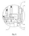
- FIG. 6 is a partial enlarged view of FIG. 5 .
- the heat conductive tubular electric heater has the following elements.
- a body 5 has a water storage tank 10 .
- a water inlet tube 6 and a water outlet tube 8 are assembled to the body 5 .
- the water inlet tube 6 is connected to the water storage tank 10 .
- a heat conductive tube 12 extends from a portion that the water inlet tube 6 enters into the water storage tank 10 .
- the heat conductive tube 12 is multi-folded in the water storage tank 10 .
- a heat electric tube 20 is arranged within the heat conductive tube 12 .
- a water path is formed in a space between an outer periphery of the electric tube 20 and an inner side of the heat conductive tube 12 .
- a water outlet tube 16 is installed at a distal end of the heat conductive tube 12 for inputting hot water into the water storage tank 10 . It is preferably that the water drain tube 16 is faced upwards.
- the heat conductive tube 12 may be installed with positioning elements 11 , connecting elements 13 , and retaining plates 19 .
- a temperature sensing element 4 is installed within the water storage tank 10 for measuring the temperature of an interior of the water storage tank 10 . Furthermore, a heating indicator 1 , a temperature controller 2 and a switch are installed at the body 5 for displaying the operation states.
- cool water enters into the water drain tube 16 and passes through an interior of the positioning element 11 to be guided into the heat conductive tube 12 . Since the electric tube 20 is installed within the heat conductive tube 12 , cool water is heated continuously and sufficiently so as to increase the temperature thereof so as to become hot water. Then the hot water is filled into the water storage tank 10 to be used afterwards. In use, the hot water flows out of the water outlet tube 8 of the water storage tank 10 .
- the heat conductive tube 12 is used to heat cool water.
- the cool water is heated by flowing through some distances of the heat conductive tube 12 .
- the water flows through the small tube and nearly closes to the heat electric tube 20 .
- the water is heated efficiently in a very short time. Dirt will not be left in the water storage tank 10 after water flows through it.
- Surplus water can be stored in the water storage tank 10 so as to supply instant hot water for using conveniently without limitation of times of uses.
- the cool water is heated sequentially by flowing through the tube, then the hot water is sent to the water storage tank 10 .
- cool water and hot water will not be mixed to enhance heating efficiently.
- the hot water is stored in water storage tank 10 after it flows through the water drain tube 16 . If the hot water is not used immediately, then the hot water will cool down.
- a water pump 9 , a first tube 91 and a second tube 92 are installed within the water storage tank 10 in order to efficiently use the cool water stored in water storage tank 10 for next time use and also to heat the cool water uniformly and quickly.
- One end of the first tube 91 is connected to a bottom of the water storage tank 10 on a predetermined, and the other end is connected to the water pump 9 .
- One end of the second tube 92 is connected to water inlet tube 6 on a predetermined, and the other end is connected to the water pump 9 .
- the water pump 9 is not actuated, and thus both the first tube 91 and the second tube 92 are not actuated, as illustrated in FIG. 4 .
- the electric heater is turned on for preheating the cool water for future usage, the water pump 9 is actuated.
- the cool water which stored in water storage tank 10 is inputting into the first tube 91 , pumping it from water pump 9 to the second tube 92 and delivering it to the water inlet tube 6 .
- the cool water is entered into heat conductive tube 12 to be heated by the electric tube 20 , by which the cool in the electric heater can be heated circularly, as illustrated in FIGS. 5 and 6 .
- the heat conductive tube 12 of the electric heater has already been heated by the electric tube 20 for a time period, it should be warmed up to a higher temperature.
- the cool water enters into the water inlet tube 6 and then to be guided into the heat conductive tube 12 , the cool water is heated as soon as possible. Therefore, the electric energy will not be wasted too mush for heating by the electric tube. So the present invention has several advantages, such as heating fast, saving electric energy and high thermal efficiency.
- the temperature sensing element 4 can control automatically the heating operation of the heat conductive tube 12 .
- the surplus water in the water storage tank 10 can be used efficiently and be heated evenly.
- the invention matches the the requirement for saving water by which the cool water does not be drained out and causes waste at the beginning of usage.
Landscapes
- Engineering & Computer Science (AREA)
- Physics & Mathematics (AREA)
- Thermal Sciences (AREA)
- Chemical & Material Sciences (AREA)
- Combustion & Propulsion (AREA)
- Mechanical Engineering (AREA)
- General Engineering & Computer Science (AREA)
- Heat-Pump Type And Storage Water Heaters (AREA)
Abstract
A heat conductive tubular electric heater is disclosed. In the heater body, a water inlet tube is connected to a heat conductive tube and an electric tube is installed within the heat conductive tube so as to form a water path between a periphery of the electric tube and an interior of the heat conductive tube. When the cool water flows into the water inlet tube entering into the electric heater, the cool water can be heated continuously by the electric tube to increase it's a temperature thereof and is heated. Besides, the heat conductive tube is assembled within a water storage tank of the electric heater for being stored therein for further use. The heater is worthy for industrial uses, because of some advantages thereof, such as heating water fast, high thermal efficiency.
Description
The present invention relates to a heat conductive tubular electric heater, and in particular to a heater body can be used to heat cool water by which the hot water can be obtained for taking a bath or cleaning.
Among many ways to heat water, both a gas heater and an electric heater are usually used. The electric heater has already been more and more popular recently since it can be installed conveniently in many places. According to functions of the electric heaters, electric heaters can be divided into two modes, one is a storage mode and the other is an instant heating mode. The disadvantages of a storage heater includes its large size, high price, slow heating. Besides, the hot water stored in a storage heater needs to be kept warm all day long, which causes electric energy to be wasted. In use, the temperature of the hot water will decrease abruptly, because the hot water was not drained out by its heating sequence and was mixed with the entering cool water. For an instant heating heater, it is difficult to adjust a suitable temperature for usage. Although a multi-stage temperature adjuster can be used in an instant heating heater, it is also inconvenient during changes of whether. If the temperature adjuster is installed, the power of the instant heating heater cannot be turned on by a faucet to heat the cool water. In addition, the instant heater needs a great quantity of electric current which causes waste of electric energy.
The primary object of the present invention is to provide an ideal and practical electric heater. The advantages of the electric heater includes fast heating, and efficient heating, which also includes the advantages of the prior art storage heaters and instant heaters.
To achieve above objects, the present invention provides a heat conductive tubular electric heater. In the heater body, a water inlet tube is connected to a heat conductive tube and an electric tube is installed within the heat conductive tube so as to form a water path between a periphery of the electric tube and an interior of the heat conductive tube. When the cool water flows into the water inlet tube entering into the electric heater, the cool water can be heated continuously by the electric tube to increase its temperature and become hot water. Besides, the heat conductive tube is assembled within a water storage tank of the electric heater, by which the hot water can be stored for waiting usage.
The various objects and advantages of the present invention will be more readily understood from the following detailed description when read in conjunction with the appended drawing.
Referring to FIGS. 1 , 2, and 3, the heat conductive tubular electric heater of the present invention is illustrated. The heat conductive tubular electric heater has the following elements. A body 5 has a water storage tank 10. A water inlet tube 6 and a water outlet tube 8 are assembled to the body 5. The water inlet tube 6 is connected to the water storage tank 10. A heat conductive tube 12 extends from a portion that the water inlet tube 6 enters into the water storage tank 10. The heat conductive tube 12 is multi-folded in the water storage tank 10. A heat electric tube 20 is arranged within the heat conductive tube 12. A water path is formed in a space between an outer periphery of the electric tube 20 and an inner side of the heat conductive tube 12. A water outlet tube 16 is installed at a distal end of the heat conductive tube 12 for inputting hot water into the water storage tank 10. It is preferably that the water drain tube 16 is faced upwards.
The heat conductive tube 12 may be installed with positioning elements 11, connecting elements 13, and retaining plates 19. A temperature sensing element 4 is installed within the water storage tank 10 for measuring the temperature of an interior of the water storage tank 10. Furthermore, a heating indicator 1, a temperature controller 2 and a switch are installed at the body 5 for displaying the operation states.
Referring to FIGS. 3 and 4 , the operation of the present invention will be described. In operation, cool water enters into the water drain tube 16 and passes through an interior of the positioning element 11 to be guided into the heat conductive tube 12. Since the electric tube 20 is installed within the heat conductive tube 12, cool water is heated continuously and sufficiently so as to increase the temperature thereof so as to become hot water. Then the hot water is filled into the water storage tank 10 to be used afterwards. In use, the hot water flows out of the water outlet tube 8 of the water storage tank 10.
In the present invention, the heat conductive tube 12 is used to heat cool water. The cool water is heated by flowing through some distances of the heat conductive tube 12. In particular, the water flows through the small tube and nearly closes to the heat electric tube 20. Thus, the water is heated efficiently in a very short time. Dirt will not be left in the water storage tank 10 after water flows through it. Surplus water can be stored in the water storage tank 10 so as to supply instant hot water for using conveniently without limitation of times of uses. In addition, the cool water is heated sequentially by flowing through the tube, then the hot water is sent to the water storage tank 10. Thus, cool water and hot water will not be mixed to enhance heating efficiently.
The hot water is stored in water storage tank 10 after it flows through the water drain tube 16. If the hot water is not used immediately, then the hot water will cool down. Referring to FIGS. 2 and 3 , a water pump 9, a first tube 91 and a second tube 92 are installed within the water storage tank 10 in order to efficiently use the cool water stored in water storage tank 10 for next time use and also to heat the cool water uniformly and quickly. One end of the first tube 91 is connected to a bottom of the water storage tank 10 on a predetermined, and the other end is connected to the water pump 9. One end of the second tube 92 is connected to water inlet tube 6 on a predetermined, and the other end is connected to the water pump 9. In ordinary situation, the water pump 9 is not actuated, and thus both the first tube 91 and the second tube 92 are not actuated, as illustrated in FIG. 4 . While the electric heater is turned on for preheating the cool water for future usage, the water pump 9 is actuated. The cool water which stored in water storage tank 10 is inputting into the first tube 91, pumping it from water pump 9 to the second tube 92 and delivering it to the water inlet tube 6. Then the cool water is entered into heat conductive tube 12 to be heated by the electric tube 20, by which the cool in the electric heater can be heated circularly, as illustrated in FIGS. 5 and 6 . Because the heat conductive tube 12 of the electric heater has already been heated by the electric tube 20 for a time period, it should be warmed up to a higher temperature. When the cool water enters into the water inlet tube 6 and then to be guided into the heat conductive tube 12, the cool water is heated as soon as possible. Therefore, the electric energy will not be wasted too mush for heating by the electric tube. So the present invention has several advantages, such as heating fast, saving electric energy and high thermal efficiency.
Because the water temperature is detected by the temperature sensing element 4, the temperature sensing element 4 can control automatically the heating operation of the heat conductive tube 12. Thus the surplus water in the water storage tank 10 can be used efficiently and be heated evenly. The invention matches the the requirement for saving water by which the cool water does not be drained out and causes waste at the beginning of usage.
The present invention is thus described, and it will be obvious that the same may be varied in many ways. Such variations are not to be regarded as a departure from the spirit and scope of the present invention, and all such modifications as would be obvious to one skilled in the art are intended to be included within the scope of the following claims.
Claims (3)
1. A heat conductive tubular electric heater comprising:
a heater body;
a water storage tank installed within the heat body for storing water;
a water inlet tube assembled to the water storage tank for supplying water;
a heat conductive tube installed within a water outlet tube; the heat conductive tube having multi-folds in the water storage tank;
an electric tube installed within the heat conductive tube so as to form a water path between an periphery of the electric tube and an interior of the heat conductive tube; one end of the heat conductive tube being connected to the water outlet tube; and
a water drain tube having an water outlet opening for releasing water into an interior of the water storage tank so as to leave from the water conductive tube;
a water outlet tube connected to a predetermined position of the water storage tank so that water can output from the water outlet tube,
wherein the heat conductive tube is formed with a plurality of positioning elements at a lower side of the water storage tank for positioning the heat conductive tube, a plurality of connecting elements at a lower side of the water storage tank for connecting different parts of the water conductive tube, and a plurality of retaining plates for retaining the water positioning elements,
wherein a water pump, a first tube and a second tube are installed within the water storage tank; the one end of the first tube 91 is connected to the bottom of the water storage tank, and the other end thereof is connected to the water pump; one end of the second tube is connected to water inlet tube, and the other end is connected to the water pump.
2. The heat conductive tubular electric heater as claimed in claim 1 , wherein a temperature sensing element is installed in the water storage tank.
3. The heat conductive tubular electric heater as claimed in claim 1 , wherein a heating indicator, a temperature controller and a switch are installed at the body.
Applications Claiming Priority (1)
| Application Number | Priority Date | Filing Date | Title |
|---|---|---|---|
| TW093208288U TWM265577U (en) | 2004-05-27 | 2004-05-27 | Heat pipe type electric water heater |
Publications (1)
| Publication Number | Publication Date |
|---|---|
| US7039305B1 true US7039305B1 (en) | 2006-05-02 |
Family
ID=36216157
Family Applications (1)
| Application Number | Title | Priority Date | Filing Date |
|---|---|---|---|
| US11/120,800 Expired - Fee Related US7039305B1 (en) | 2004-05-27 | 2005-05-04 | Heat conductive tubular electric heater |
Country Status (2)
| Country | Link |
|---|---|
| US (1) | US7039305B1 (en) |
| TW (1) | TWM265577U (en) |
Cited By (15)
| Publication number | Priority date | Publication date | Assignee | Title |
|---|---|---|---|---|
| US20070166017A1 (en) * | 2006-01-02 | 2007-07-19 | Sun-Duc Kwon | Instant water heating apparatus for cleaning machine |
| US20080285964A1 (en) * | 2007-05-07 | 2008-11-20 | Sullivan Joseph M | Modular heating system for tankless water heater |
| US20100059599A1 (en) * | 2008-09-11 | 2010-03-11 | Ray King | Closed loop heating system |
| CN102062475A (en) * | 2010-09-01 | 2011-05-18 | 张英华 | Fast type electric water heater |
| US20120061382A1 (en) * | 2010-09-10 | 2012-03-15 | Shun-Chi Yang | High-Efficiency Water Boiling Device |
| US20130016959A1 (en) * | 2011-03-04 | 2013-01-17 | Ray King | Radiant heating system and boiler housing for use therein |
| WO2013078617A1 (en) * | 2011-11-29 | 2013-06-06 | Guo Shijun | Electromagnetic water heater and water tank with arched water channel |
| US20130264326A1 (en) * | 2012-04-04 | 2013-10-10 | Gaumer Company, Inc. | High Velocity Fluid Flow Electric Heater |
| US20140023352A1 (en) * | 2012-07-17 | 2014-01-23 | Eemax, Inc. | Fluid heating system and instant fluid heating device |
| US8933372B2 (en) | 2006-06-29 | 2015-01-13 | Dynacurrent Technologies, Inc. | Engine pre-heater system |
| US9091457B2 (en) | 2011-03-04 | 2015-07-28 | Dynacurrent Technologies, Inc. | Electro-thermal heating system |
| US20160320092A1 (en) * | 2015-05-01 | 2016-11-03 | Carl Snyder | Series of Tanks That Forestall Mixing Fluids of Non-homogeneous Temperatures |
| US9702585B2 (en) | 2014-12-17 | 2017-07-11 | Eemax, Inc. | Tankless electric water heater |
| US10139136B2 (en) | 2012-12-21 | 2018-11-27 | Eemax, Inc. | Next generation bare wire water heater |
| US10222091B2 (en) | 2012-07-17 | 2019-03-05 | Eemax, Inc. | Next generation modular heating system |
Citations (6)
| Publication number | Priority date | Publication date | Assignee | Title |
|---|---|---|---|---|
| US4567350A (en) * | 1983-01-06 | 1986-01-28 | Todd Jr Alvin E | Compact high flow rate electric instantaneous water heater |
| US5216743A (en) * | 1990-05-10 | 1993-06-01 | Seitz David E | Thermo-plastic heat exchanger |
| US5408578A (en) * | 1993-01-25 | 1995-04-18 | Bolivar; Luis | Tankless water heater assembly |
| US5438642A (en) * | 1993-07-13 | 1995-08-01 | Instantaneous Thermal Systems, Inc. | Instantaneous water heater |
| US6246831B1 (en) * | 1999-06-16 | 2001-06-12 | David Seitz | Fluid heating control system |
| US6389226B1 (en) * | 2001-05-09 | 2002-05-14 | Envirotech Systems Worldwide, Inc. | Modular tankless electronic water heater |
-
2004
- 2004-05-27 TW TW093208288U patent/TWM265577U/en not_active IP Right Cessation
-
2005
- 2005-05-04 US US11/120,800 patent/US7039305B1/en not_active Expired - Fee Related
Patent Citations (6)
| Publication number | Priority date | Publication date | Assignee | Title |
|---|---|---|---|---|
| US4567350A (en) * | 1983-01-06 | 1986-01-28 | Todd Jr Alvin E | Compact high flow rate electric instantaneous water heater |
| US5216743A (en) * | 1990-05-10 | 1993-06-01 | Seitz David E | Thermo-plastic heat exchanger |
| US5408578A (en) * | 1993-01-25 | 1995-04-18 | Bolivar; Luis | Tankless water heater assembly |
| US5438642A (en) * | 1993-07-13 | 1995-08-01 | Instantaneous Thermal Systems, Inc. | Instantaneous water heater |
| US6246831B1 (en) * | 1999-06-16 | 2001-06-12 | David Seitz | Fluid heating control system |
| US6389226B1 (en) * | 2001-05-09 | 2002-05-14 | Envirotech Systems Worldwide, Inc. | Modular tankless electronic water heater |
Cited By (28)
| Publication number | Priority date | Publication date | Assignee | Title |
|---|---|---|---|---|
| US7330645B2 (en) * | 2006-01-02 | 2008-02-12 | Novita Co., Ltd. | Instant water heating apparatus for cleaning machine |
| US20070166017A1 (en) * | 2006-01-02 | 2007-07-19 | Sun-Duc Kwon | Instant water heating apparatus for cleaning machine |
| US8933372B2 (en) | 2006-06-29 | 2015-01-13 | Dynacurrent Technologies, Inc. | Engine pre-heater system |
| US20080285964A1 (en) * | 2007-05-07 | 2008-11-20 | Sullivan Joseph M | Modular heating system for tankless water heater |
| US8165461B2 (en) * | 2007-05-07 | 2012-04-24 | Sullivan Joseph M | Modular heating system for tankless water heater |
| US20100059599A1 (en) * | 2008-09-11 | 2010-03-11 | Ray King | Closed loop heating system |
| US9429330B2 (en) | 2008-09-11 | 2016-08-30 | Dynacurrent Technologies, Inc. | Closed loop heating system |
| CN102062475A (en) * | 2010-09-01 | 2011-05-18 | 张英华 | Fast type electric water heater |
| CN102062475B (en) * | 2010-09-01 | 2013-01-30 | 张英华 | Fast type electric water heater |
| US20120061382A1 (en) * | 2010-09-10 | 2012-03-15 | Shun-Chi Yang | High-Efficiency Water Boiling Device |
| US8450666B2 (en) * | 2010-09-10 | 2013-05-28 | Shun-Chi Yang | High-efficiency water boiling device |
| US20130016959A1 (en) * | 2011-03-04 | 2013-01-17 | Ray King | Radiant heating system and boiler housing for use therein |
| US9091457B2 (en) | 2011-03-04 | 2015-07-28 | Dynacurrent Technologies, Inc. | Electro-thermal heating system |
| US8855475B2 (en) * | 2011-03-04 | 2014-10-07 | Dynacurrent Technologies, Inc. | Radiant heating system and boiler housing for use therein |
| WO2013078617A1 (en) * | 2011-11-29 | 2013-06-06 | Guo Shijun | Electromagnetic water heater and water tank with arched water channel |
| US9074819B2 (en) * | 2012-04-04 | 2015-07-07 | Gaumer Company, Inc. | High velocity fluid flow electric heater |
| US20130264326A1 (en) * | 2012-04-04 | 2013-10-10 | Gaumer Company, Inc. | High Velocity Fluid Flow Electric Heater |
| US9140466B2 (en) * | 2012-07-17 | 2015-09-22 | Eemax, Inc. | Fluid heating system and instant fluid heating device |
| US9410720B2 (en) | 2012-07-17 | 2016-08-09 | Eemax, Inc. | Fluid heating system and instant fluid heating device |
| US20160245546A1 (en) * | 2012-07-17 | 2016-08-25 | Eemax, Inc. | Fluid heating system and instant fluid heating device |
| US20140023352A1 (en) * | 2012-07-17 | 2014-01-23 | Eemax, Inc. | Fluid heating system and instant fluid heating device |
| US10222091B2 (en) | 2012-07-17 | 2019-03-05 | Eemax, Inc. | Next generation modular heating system |
| US10203131B2 (en) | 2012-07-17 | 2019-02-12 | Eemax, Inc. | Fluid heating system and instant fluid heating device |
| US9857096B2 (en) * | 2012-07-17 | 2018-01-02 | Eemax, Inc. | Fluid heating system and instant fluid heating device |
| US10139136B2 (en) | 2012-12-21 | 2018-11-27 | Eemax, Inc. | Next generation bare wire water heater |
| US9702585B2 (en) | 2014-12-17 | 2017-07-11 | Eemax, Inc. | Tankless electric water heater |
| US10655890B2 (en) | 2014-12-17 | 2020-05-19 | Eemax, Inc. | Tankless electric water heater |
| US20160320092A1 (en) * | 2015-05-01 | 2016-11-03 | Carl Snyder | Series of Tanks That Forestall Mixing Fluids of Non-homogeneous Temperatures |
Also Published As
| Publication number | Publication date |
|---|---|
| TWM265577U (en) | 2005-05-21 |
Similar Documents
| Publication | Publication Date | Title |
|---|---|---|
| US7039305B1 (en) | Heat conductive tubular electric heater | |
| CN201715691U (en) | Electrically powered water heater with piston | |
| US20090067824A1 (en) | Water heater Module | |
| TWI591302B (en) | Water storage water heater | |
| CN110044066A (en) | Storage-type gas-heating water heater and control method | |
| CN108361998A (en) | The control method of Teat pump boiler | |
| US7567750B2 (en) | Instantaneous water heater with a heating tube | |
| HU229686B1 (en) | Water heater assembly | |
| US11359825B2 (en) | Energy storage device, method for storing and supplying energy using the same | |
| RU2519115C2 (en) | Built-in heating unit of water heater with heat accumulator | |
| CN203848488U (en) | Water heater | |
| CN113757773B (en) | Heating stove and control method thereof | |
| CN202581799U (en) | Phase-change thermal-storage type electric water heater | |
| KR20010008335A (en) | Electric boiler using thermal oil | |
| CN210107725U (en) | Rapid heating water storage type electric water heater | |
| CN103829655A (en) | Water bed with function of automatic temperature adjustment | |
| CN208458248U (en) | A kind of oil temperature machine cartridge heater modular construction | |
| CN208170748U (en) | Water heater | |
| CN2788079Y (en) | Heat pipe type electric water heater | |
| CN106839446B (en) | Water heater and control method thereof | |
| CN201281447Y (en) | Quickly heater | |
| CN211084471U (en) | Solar energy-saving hot water system | |
| CN217937886U (en) | Steam generator and cooking utensil | |
| CN216693986U (en) | Quick heating postposition heat-preserving gas water heater | |
| CN207760065U (en) | Purifier |
Legal Events
| Date | Code | Title | Description |
|---|---|---|---|
| FPAY | Fee payment |
Year of fee payment: 4 |
|
| REMI | Maintenance fee reminder mailed | ||
| LAPS | Lapse for failure to pay maintenance fees | ||
| STCH | Information on status: patent discontinuation |
Free format text: PATENT EXPIRED DUE TO NONPAYMENT OF MAINTENANCE FEES UNDER 37 CFR 1.362 |
|
| FP | Lapsed due to failure to pay maintenance fee |
Effective date: 20140502 |