US7025159B2 - Cooling system for a vehicle battery - Google Patents
Cooling system for a vehicle battery Download PDFInfo
- Publication number
- US7025159B2 US7025159B2 US10/605,179 US60517903A US7025159B2 US 7025159 B2 US7025159 B2 US 7025159B2 US 60517903 A US60517903 A US 60517903A US 7025159 B2 US7025159 B2 US 7025159B2
- Authority
- US
- United States
- Prior art keywords
- battery
- air
- vehicle
- duct
- duct system
- Prior art date
- Legal status (The legal status is an assumption and is not a legal conclusion. Google has not performed a legal analysis and makes no representation as to the accuracy of the status listed.)
- Expired - Lifetime, expires
Links
Images


Classifications
-
- B—PERFORMING OPERATIONS; TRANSPORTING
- B60—VEHICLES IN GENERAL
- B60H—ARRANGEMENTS OF HEATING, COOLING, VENTILATING OR OTHER AIR-TREATING DEVICES SPECIALLY ADAPTED FOR PASSENGER OR GOODS SPACES OF VEHICLES
- B60H1/00—Heating, cooling or ventilating [HVAC] devices
- B60H1/00357—Air-conditioning arrangements specially adapted for particular vehicles
- B60H1/00385—Air-conditioning arrangements specially adapted for particular vehicles for vehicles having an electrical drive, e.g. hybrid or fuel cell
-
- B—PERFORMING OPERATIONS; TRANSPORTING
- B60—VEHICLES IN GENERAL
- B60H—ARRANGEMENTS OF HEATING, COOLING, VENTILATING OR OTHER AIR-TREATING DEVICES SPECIALLY ADAPTED FOR PASSENGER OR GOODS SPACES OF VEHICLES
- B60H1/00—Heating, cooling or ventilating [HVAC] devices
- B60H1/00271—HVAC devices specially adapted for particular vehicle parts or components and being connected to the vehicle HVAC unit
- B60H1/00278—HVAC devices specially adapted for particular vehicle parts or components and being connected to the vehicle HVAC unit for the battery
-
- B—PERFORMING OPERATIONS; TRANSPORTING
- B60—VEHICLES IN GENERAL
- B60K—ARRANGEMENT OR MOUNTING OF PROPULSION UNITS OR OF TRANSMISSIONS IN VEHICLES; ARRANGEMENT OR MOUNTING OF PLURAL DIVERSE PRIME-MOVERS IN VEHICLES; AUXILIARY DRIVES FOR VEHICLES; INSTRUMENTATION OR DASHBOARDS FOR VEHICLES; ARRANGEMENTS IN CONNECTION WITH COOLING, AIR INTAKE, GAS EXHAUST OR FUEL SUPPLY OF PROPULSION UNITS IN VEHICLES
- B60K1/00—Arrangement or mounting of electrical propulsion units
- B60K1/04—Arrangement or mounting of electrical propulsion units of the electric storage means for propulsion
-
- B—PERFORMING OPERATIONS; TRANSPORTING
- B60—VEHICLES IN GENERAL
- B60L—PROPULSION OF ELECTRICALLY-PROPELLED VEHICLES; SUPPLYING ELECTRIC POWER FOR AUXILIARY EQUIPMENT OF ELECTRICALLY-PROPELLED VEHICLES; ELECTRODYNAMIC BRAKE SYSTEMS FOR VEHICLES IN GENERAL; MAGNETIC SUSPENSION OR LEVITATION FOR VEHICLES; MONITORING OPERATING VARIABLES OF ELECTRICALLY-PROPELLED VEHICLES; ELECTRIC SAFETY DEVICES FOR ELECTRICALLY-PROPELLED VEHICLES
- B60L1/00—Supplying electric power to auxiliary equipment of vehicles
- B60L1/003—Supplying electric power to auxiliary equipment of vehicles to auxiliary motors, e.g. for pumps, compressors
-
- B—PERFORMING OPERATIONS; TRANSPORTING
- B60—VEHICLES IN GENERAL
- B60L—PROPULSION OF ELECTRICALLY-PROPELLED VEHICLES; SUPPLYING ELECTRIC POWER FOR AUXILIARY EQUIPMENT OF ELECTRICALLY-PROPELLED VEHICLES; ELECTRODYNAMIC BRAKE SYSTEMS FOR VEHICLES IN GENERAL; MAGNETIC SUSPENSION OR LEVITATION FOR VEHICLES; MONITORING OPERATING VARIABLES OF ELECTRICALLY-PROPELLED VEHICLES; ELECTRIC SAFETY DEVICES FOR ELECTRICALLY-PROPELLED VEHICLES
- B60L50/00—Electric propulsion with power supplied within the vehicle
- B60L50/50—Electric propulsion with power supplied within the vehicle using propulsion power supplied by batteries or fuel cells
- B60L50/60—Electric propulsion with power supplied within the vehicle using propulsion power supplied by batteries or fuel cells using power supplied by batteries
- B60L50/64—Constructional details of batteries specially adapted for electric vehicles
-
- B—PERFORMING OPERATIONS; TRANSPORTING
- B60—VEHICLES IN GENERAL
- B60L—PROPULSION OF ELECTRICALLY-PROPELLED VEHICLES; SUPPLYING ELECTRIC POWER FOR AUXILIARY EQUIPMENT OF ELECTRICALLY-PROPELLED VEHICLES; ELECTRODYNAMIC BRAKE SYSTEMS FOR VEHICLES IN GENERAL; MAGNETIC SUSPENSION OR LEVITATION FOR VEHICLES; MONITORING OPERATING VARIABLES OF ELECTRICALLY-PROPELLED VEHICLES; ELECTRIC SAFETY DEVICES FOR ELECTRICALLY-PROPELLED VEHICLES
- B60L50/00—Electric propulsion with power supplied within the vehicle
- B60L50/50—Electric propulsion with power supplied within the vehicle using propulsion power supplied by batteries or fuel cells
- B60L50/60—Electric propulsion with power supplied within the vehicle using propulsion power supplied by batteries or fuel cells using power supplied by batteries
- B60L50/66—Arrangements of batteries
-
- B—PERFORMING OPERATIONS; TRANSPORTING
- B60—VEHICLES IN GENERAL
- B60L—PROPULSION OF ELECTRICALLY-PROPELLED VEHICLES; SUPPLYING ELECTRIC POWER FOR AUXILIARY EQUIPMENT OF ELECTRICALLY-PROPELLED VEHICLES; ELECTRODYNAMIC BRAKE SYSTEMS FOR VEHICLES IN GENERAL; MAGNETIC SUSPENSION OR LEVITATION FOR VEHICLES; MONITORING OPERATING VARIABLES OF ELECTRICALLY-PROPELLED VEHICLES; ELECTRIC SAFETY DEVICES FOR ELECTRICALLY-PROPELLED VEHICLES
- B60L58/00—Methods or circuit arrangements for monitoring or controlling batteries or fuel cells, specially adapted for electric vehicles
- B60L58/10—Methods or circuit arrangements for monitoring or controlling batteries or fuel cells, specially adapted for electric vehicles for monitoring or controlling batteries
- B60L58/18—Methods or circuit arrangements for monitoring or controlling batteries or fuel cells, specially adapted for electric vehicles for monitoring or controlling batteries of two or more battery modules
- B60L58/21—Methods or circuit arrangements for monitoring or controlling batteries or fuel cells, specially adapted for electric vehicles for monitoring or controlling batteries of two or more battery modules having the same nominal voltage
-
- B—PERFORMING OPERATIONS; TRANSPORTING
- B60—VEHICLES IN GENERAL
- B60L—PROPULSION OF ELECTRICALLY-PROPELLED VEHICLES; SUPPLYING ELECTRIC POWER FOR AUXILIARY EQUIPMENT OF ELECTRICALLY-PROPELLED VEHICLES; ELECTRODYNAMIC BRAKE SYSTEMS FOR VEHICLES IN GENERAL; MAGNETIC SUSPENSION OR LEVITATION FOR VEHICLES; MONITORING OPERATING VARIABLES OF ELECTRICALLY-PROPELLED VEHICLES; ELECTRIC SAFETY DEVICES FOR ELECTRICALLY-PROPELLED VEHICLES
- B60L58/00—Methods or circuit arrangements for monitoring or controlling batteries or fuel cells, specially adapted for electric vehicles
- B60L58/10—Methods or circuit arrangements for monitoring or controlling batteries or fuel cells, specially adapted for electric vehicles for monitoring or controlling batteries
- B60L58/24—Methods or circuit arrangements for monitoring or controlling batteries or fuel cells, specially adapted for electric vehicles for monitoring or controlling batteries for controlling the temperature of batteries
- B60L58/26—Methods or circuit arrangements for monitoring or controlling batteries or fuel cells, specially adapted for electric vehicles for monitoring or controlling batteries for controlling the temperature of batteries by cooling
-
- B—PERFORMING OPERATIONS; TRANSPORTING
- B60—VEHICLES IN GENERAL
- B60H—ARRANGEMENTS OF HEATING, COOLING, VENTILATING OR OTHER AIR-TREATING DEVICES SPECIALLY ADAPTED FOR PASSENGER OR GOODS SPACES OF VEHICLES
- B60H1/00—Heating, cooling or ventilating [HVAC] devices
- B60H1/00271—HVAC devices specially adapted for particular vehicle parts or components and being connected to the vehicle HVAC unit
- B60H2001/003—Component temperature regulation using an air flow
-
- B—PERFORMING OPERATIONS; TRANSPORTING
- B60—VEHICLES IN GENERAL
- B60K—ARRANGEMENT OR MOUNTING OF PROPULSION UNITS OR OF TRANSMISSIONS IN VEHICLES; ARRANGEMENT OR MOUNTING OF PLURAL DIVERSE PRIME-MOVERS IN VEHICLES; AUXILIARY DRIVES FOR VEHICLES; INSTRUMENTATION OR DASHBOARDS FOR VEHICLES; ARRANGEMENTS IN CONNECTION WITH COOLING, AIR INTAKE, GAS EXHAUST OR FUEL SUPPLY OF PROPULSION UNITS IN VEHICLES
- B60K1/00—Arrangement or mounting of electrical propulsion units
- B60K2001/003—Arrangement or mounting of electrical propulsion units with means for cooling the electrical propulsion units
- B60K2001/005—Arrangement or mounting of electrical propulsion units with means for cooling the electrical propulsion units the electric storage means
-
- B—PERFORMING OPERATIONS; TRANSPORTING
- B60—VEHICLES IN GENERAL
- B60L—PROPULSION OF ELECTRICALLY-PROPELLED VEHICLES; SUPPLYING ELECTRIC POWER FOR AUXILIARY EQUIPMENT OF ELECTRICALLY-PROPELLED VEHICLES; ELECTRODYNAMIC BRAKE SYSTEMS FOR VEHICLES IN GENERAL; MAGNETIC SUSPENSION OR LEVITATION FOR VEHICLES; MONITORING OPERATING VARIABLES OF ELECTRICALLY-PROPELLED VEHICLES; ELECTRIC SAFETY DEVICES FOR ELECTRICALLY-PROPELLED VEHICLES
- B60L2240/00—Control parameters of input or output; Target parameters
- B60L2240/10—Vehicle control parameters
- B60L2240/34—Cabin temperature
-
- B—PERFORMING OPERATIONS; TRANSPORTING
- B60—VEHICLES IN GENERAL
- B60L—PROPULSION OF ELECTRICALLY-PROPELLED VEHICLES; SUPPLYING ELECTRIC POWER FOR AUXILIARY EQUIPMENT OF ELECTRICALLY-PROPELLED VEHICLES; ELECTRODYNAMIC BRAKE SYSTEMS FOR VEHICLES IN GENERAL; MAGNETIC SUSPENSION OR LEVITATION FOR VEHICLES; MONITORING OPERATING VARIABLES OF ELECTRICALLY-PROPELLED VEHICLES; ELECTRIC SAFETY DEVICES FOR ELECTRICALLY-PROPELLED VEHICLES
- B60L2240/00—Control parameters of input or output; Target parameters
- B60L2240/40—Drive Train control parameters
- B60L2240/54—Drive Train control parameters related to batteries
- B60L2240/545—Temperature
-
- B—PERFORMING OPERATIONS; TRANSPORTING
- B60—VEHICLES IN GENERAL
- B60L—PROPULSION OF ELECTRICALLY-PROPELLED VEHICLES; SUPPLYING ELECTRIC POWER FOR AUXILIARY EQUIPMENT OF ELECTRICALLY-PROPELLED VEHICLES; ELECTRODYNAMIC BRAKE SYSTEMS FOR VEHICLES IN GENERAL; MAGNETIC SUSPENSION OR LEVITATION FOR VEHICLES; MONITORING OPERATING VARIABLES OF ELECTRICALLY-PROPELLED VEHICLES; ELECTRIC SAFETY DEVICES FOR ELECTRICALLY-PROPELLED VEHICLES
- B60L2240/00—Control parameters of input or output; Target parameters
- B60L2240/60—Navigation input
- B60L2240/66—Ambient conditions
- B60L2240/662—Temperature
-
- B—PERFORMING OPERATIONS; TRANSPORTING
- B60—VEHICLES IN GENERAL
- B60W—CONJOINT CONTROL OF VEHICLE SUB-UNITS OF DIFFERENT TYPE OR DIFFERENT FUNCTION; CONTROL SYSTEMS SPECIALLY ADAPTED FOR HYBRID VEHICLES; ROAD VEHICLE DRIVE CONTROL SYSTEMS FOR PURPOSES NOT RELATED TO THE CONTROL OF A PARTICULAR SUB-UNIT
- B60W2510/00—Input parameters relating to a particular sub-units
- B60W2510/24—Energy storage means
- B60W2510/242—Energy storage means for electrical energy
- B60W2510/244—Charge state
-
- B—PERFORMING OPERATIONS; TRANSPORTING
- B60—VEHICLES IN GENERAL
- B60W—CONJOINT CONTROL OF VEHICLE SUB-UNITS OF DIFFERENT TYPE OR DIFFERENT FUNCTION; CONTROL SYSTEMS SPECIALLY ADAPTED FOR HYBRID VEHICLES; ROAD VEHICLE DRIVE CONTROL SYSTEMS FOR PURPOSES NOT RELATED TO THE CONTROL OF A PARTICULAR SUB-UNIT
- B60W2510/00—Input parameters relating to a particular sub-units
- B60W2510/24—Energy storage means
- B60W2510/242—Energy storage means for electrical energy
- B60W2510/246—Temperature
-
- B—PERFORMING OPERATIONS; TRANSPORTING
- B60—VEHICLES IN GENERAL
- B60W—CONJOINT CONTROL OF VEHICLE SUB-UNITS OF DIFFERENT TYPE OR DIFFERENT FUNCTION; CONTROL SYSTEMS SPECIALLY ADAPTED FOR HYBRID VEHICLES; ROAD VEHICLE DRIVE CONTROL SYSTEMS FOR PURPOSES NOT RELATED TO THE CONTROL OF A PARTICULAR SUB-UNIT
- B60W2555/00—Input parameters relating to exterior conditions, not covered by groups B60W2552/00, B60W2554/00
- B60W2555/20—Ambient conditions, e.g. wind or rain
-
- Y—GENERAL TAGGING OF NEW TECHNOLOGICAL DEVELOPMENTS; GENERAL TAGGING OF CROSS-SECTIONAL TECHNOLOGIES SPANNING OVER SEVERAL SECTIONS OF THE IPC; TECHNICAL SUBJECTS COVERED BY FORMER USPC CROSS-REFERENCE ART COLLECTIONS [XRACs] AND DIGESTS
- Y02—TECHNOLOGIES OR APPLICATIONS FOR MITIGATION OR ADAPTATION AGAINST CLIMATE CHANGE
- Y02T—CLIMATE CHANGE MITIGATION TECHNOLOGIES RELATED TO TRANSPORTATION
- Y02T10/00—Road transport of goods or passengers
- Y02T10/60—Other road transportation technologies with climate change mitigation effect
- Y02T10/70—Energy storage systems for electromobility, e.g. batteries
-
- Y—GENERAL TAGGING OF NEW TECHNOLOGICAL DEVELOPMENTS; GENERAL TAGGING OF CROSS-SECTIONAL TECHNOLOGIES SPANNING OVER SEVERAL SECTIONS OF THE IPC; TECHNICAL SUBJECTS COVERED BY FORMER USPC CROSS-REFERENCE ART COLLECTIONS [XRACs] AND DIGESTS
- Y02—TECHNOLOGIES OR APPLICATIONS FOR MITIGATION OR ADAPTATION AGAINST CLIMATE CHANGE
- Y02T—CLIMATE CHANGE MITIGATION TECHNOLOGIES RELATED TO TRANSPORTATION
- Y02T10/00—Road transport of goods or passengers
- Y02T10/60—Other road transportation technologies with climate change mitigation effect
- Y02T10/72—Electric energy management in electromobility
-
- Y—GENERAL TAGGING OF NEW TECHNOLOGICAL DEVELOPMENTS; GENERAL TAGGING OF CROSS-SECTIONAL TECHNOLOGIES SPANNING OVER SEVERAL SECTIONS OF THE IPC; TECHNICAL SUBJECTS COVERED BY FORMER USPC CROSS-REFERENCE ART COLLECTIONS [XRACs] AND DIGESTS
- Y02—TECHNOLOGIES OR APPLICATIONS FOR MITIGATION OR ADAPTATION AGAINST CLIMATE CHANGE
- Y02T—CLIMATE CHANGE MITIGATION TECHNOLOGIES RELATED TO TRANSPORTATION
- Y02T10/00—Road transport of goods or passengers
- Y02T10/80—Technologies aiming to reduce greenhouse gasses emissions common to all road transportation technologies
- Y02T10/88—Optimized components or subsystems, e.g. lighting, actively controlled glasses
-
- Y—GENERAL TAGGING OF NEW TECHNOLOGICAL DEVELOPMENTS; GENERAL TAGGING OF CROSS-SECTIONAL TECHNOLOGIES SPANNING OVER SEVERAL SECTIONS OF THE IPC; TECHNICAL SUBJECTS COVERED BY FORMER USPC CROSS-REFERENCE ART COLLECTIONS [XRACs] AND DIGESTS
- Y02—TECHNOLOGIES OR APPLICATIONS FOR MITIGATION OR ADAPTATION AGAINST CLIMATE CHANGE
- Y02T—CLIMATE CHANGE MITIGATION TECHNOLOGIES RELATED TO TRANSPORTATION
- Y02T90/00—Enabling technologies or technologies with a potential or indirect contribution to GHG emissions mitigation
- Y02T90/10—Technologies relating to charging of electric vehicles
- Y02T90/16—Information or communication technologies improving the operation of electric vehicles
Definitions
- the present invention relates to a system for cooling a vehicle battery.
- Electric vehicles which utilize electricity, and in particular an electric motor, to at least assist in powering the vehicle.
- electric vehicles which are powered exclusively by an electric motor
- hybrid electric vehicles HEV
- fuel cell vehicles or hybrid fuel cell vehicles, just to name a few.
- the electric motor used in such vehicles may have an electrical power source such as a fuel cell or a battery.
- the temperature of the battery can increase significantly when the motor is used for extended periods of time.
- the increase in battery temperature may be compounded when the battery is confined to a relatively small, enclosed space. If the increase in battery temperature is left unchecked, the battery life may be reduced.
- the same heat exchanger is used to cool both passenger compartment air and battery compartment air.
- a number of air discharge ports may be opened or closed to control the flow of air into the passenger compartment; however, the temperature of the air flowing into the passenger compartment will be the same as the temperature of the air flowing into the battery compartment. This is because a single heat exchanger is used to cool the air flowing into both spaces.
- the air that flows into the battery chamber is discharged outside the vehicle, while the air flowing into the passenger compartment may be discharged outside the vehicle, or recirculated back into the passenger compartment.
- recirculating the air may provide the added benefit of reducing the moisture content of the air passing through the heat exchanger. This could reduce the amount of condensate formed and help prevent icing of the heat exchanger.
- Matsuno et al. describes a system for cooling a battery, wherein batteries inside a battery chamber are cooled by air taken from the vehicle passenger compartment. After passing through the battery compartment, the air may be recirculated into the passenger compartment, or discharged through an exhaust duct.
- One limitation of the system described in Matsuno et al. is its reliance on air from the vehicle passenger compartment to cool the batteries. Because the vehicle occupants determine the passenger compartment temperature based on their own comfort level, the air in the passenger compartment may be too warm to adequately cool the batteries. Just as in the system described in Tajiri et al., such a situation presents a conflict between the comfort level of the vehicle occupants and the need to cool the batteries.
- a system for cooling a battery that provides for recirculation of the air from the battery compartment and back through a heat exchanger so as to cool the air more efficiently, and thereby provide an energy savings.
- a cooling system for a battery in a vehicle having a passenger compartment includes an air intake for receiving air from an ambient environment outside the vehicle.
- a duct system is capable of providing communication between the air intake and the battery.
- the duct system is configured to inhibit airflow from the duct system into the vehicle passenger compartment.
- a fan cooperates with the duct system for moving air through at least a portion of the duct system and across the battery.
- a heat exchanger cooperates with the duct system and is selectively operable to cool air flowing in the duct system before the flowing air reaches the battery.
- the invention also provides a cooling system for a battery in a vehicle having a passenger compartment.
- the cooling system includes an air intake for receiving ambient air from outside the vehicle.
- a duct system includes first and second duct subsystems.
- the first duct subsystem is disposed between the air intake and the battery for providing an air flow path from the air intake to the battery.
- the second duct subsystem is disposed between the battery and the first duct subsystem, and provides an airflow path from the battery to the first duct subsystem.
- the duct system is configured to selectively inhibit airflow through at least a portion of the first and second duct subsystems.
- a fan cooperates with the duct system for moving air through at least a portion of the duct system and across the battery.
- a heat exchanger cooperates with the duct system and is selectively operable to cool air flowing in the duct system before the flowing air reaches the battery.
- the invention further provides a vehicle having a passenger compartment and a battery.
- the vehicle includes a battery cooling system having an air intake for receiving air from an ambient environment outside the vehicle.
- a duct system is configured to selectively provide communication between the air intake and the battery, and is further configured to inhibit communication between the passenger compartment and the battery.
- the battery cooling system also includes a fan that cooperates with the duct system for moving air through at least a portion of the duct system and across the battery.
- a heat exchanger cooperates with the duct system and is selectively operable to cool air flowing in the duct system before the flowing air reaches the battery.
- FIG. 1 is a partial fragmentary isometric view of a vehicle, including a battery cooling system in accordance with the present invention
- FIG. 2 is a partial fragmentary isometric view of a portion of the battery cooling system, including an air intake and a duct system;
- FIG. 3 is a side view of the vehicle shown in FIG. 1 , including a vehicle air intake disposed along an edge of a rear quarter window;
- FIG. 4 is a partial fragmentary isometric view of a portion of the battery cooling system, including a pair of fans;
- FIG. 5 is a partial fragmentary side view of a portion of the battery cooling system, including a pair of movable baffles;
- FIG. 6 is a partial fragmentary isometric view of a portion of the cooling system, including an air extractor
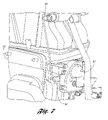
- FIG. 7 is a partial fragmentary isometric view of a portion of the battery cooling system, including a mechanism for moving the movable baffles;
- FIG. 8 is a schematic representation of a control system used to control the battery cooling system.
- FIG. 9 is a rear plan view of a vehicle, illustrating the compact nature of the battery cooling system.
- FIG. 1 shows a cooling system 10 for cooling a battery assembly 12 in a hybrid electric vehicle 14 , only a portion of which is shown in FIG. 1 .
- a cooling system such as the cooling system 10
- a pure electric vehicle, a fuel cell vehicle, or a hybrid fuel cell vehicle may also have battery assemblies or other heat generating equipment that require cooling, and would therefore benefit from the use of a cooling system, such as the cooling system 10 .
- the cooling system 10 includes an air intake 16 that is configured to receive air from an ambient environment outside the vehicle 14 .
- the air intake 16 of the cooling system 10 is connected to a vehicle air intake 18 , which is disposed in a portion of a rear quarter window 20 .
- FIG. 3 shows the rear quarter window 20 and a vehicle air intake 18 as viewed from outside the vehicle 14 .
- a vehicle air intake can be located on other parts of a vehicle; however, having a vehicle air intake, such as the air intake 18 , located relatively high-up on a vehicle, may help reduce the intake of water and debris from the road.
- Locating an air intake high-up on the vehicle can also help avoid water intake if, for example, the vehicle is used to launch a boat. In such situations, a lower portion of the vehicle may become submerged; thus, it may be an added benefit to locate the air intake above the boat launch water line. Such an air intake can also be beneficial for off-road driving.
- the cooling system 10 includes a duct system 22 , which, as explained more fully below, can selectively provide communication between the air intake 16 and the battery assembly 12 .
- the duct system 22 is also configured to inhibit airflow between the duct system 22 and a vehicle passenger compartment, for example, passenger compartment 24 shown in FIG. 3 . Because the cooling system 10 is capable of receiving air from outside the vehicle through the air intake 16 , and because the duct system 22 is configured to inhibit airflow to or from the passenger compartment 24 , the temperature of the air provided by the cooling system 10 to the battery assembly 12 is independent of the temperature of the passenger compartment 24 .
- the cooling system 10 includes a pair of fans 26 , 28 which move air through the duct system 22 and across the battery assembly 12 .
- the cooling system 10 also includes a heat exchanger, which, in the embodiment shown in FIG. 5 , is an evaporator coil 30 .
- the evaporator coil 30 cooperates with the duct system 22 , and can be selectively operated to cool the air flowing through the duct system 22 before it reaches the battery assembly 12 .
- a heat exchanger, such as the evaporator coil 30 may be any one of a number of different types of heat exchangers which remove heat from the air flowing through the duct system 22 .
- an air filter 31 is disposed in the duct system 22 for filtering the air before it reaches the evaporator coil 30 .
- the evaporator coil 30 is part of an air conditioning system.
- Such an air conditioning system may have more than one evaporator coil in the same system to cool different spaces within a vehicle.
- One such cooling system is described in U.S. patent application, publication no. 2005/0056035 entitled “Vehicle Cooling System”, filed on Sep. 12, 2003, and which is hereby incorporated herein by reference.
- the evaporator coil 30 receives a refrigerant through a refrigeration line 32 when the ambient air outside the vehicle is too warm to adequately cool the battery assembly 12 .
- Refrigerant in the refrigeration line 32 flows through a thermal expansion valve 34 prior to reaching the evaporator coil 30 .
- the cooling system 10 is provided with a drain line 36 to allow condensate to leave the duct system 22 .
- a check valve 38 provides for one way flow, such that unfiltered air will not rise back into the duct system 22 .
- a second drain line 39 is in communication with the vehicle air intake 18 , for draining water that may be taken in from the ambient air outside the vehicle.
- a thermistor 41 configured to monitor the air temperature adjacent the evaporator coil 30 . If the thermistor 41 senses a temperature that is below a predetermined temperature, the flow of refrigerant through the evaporator coil 30 is stopped. This prevents the undesirable build-up of ice on the evaporator coil 30 .
- the duct system 22 includes first, second and third duct subsystems 40 , 42 and 44 , respectively.
- the first duct subsystem 40 is disposed between the air intake 16 and the battery assembly 12 , and provides an airflow path from the air intake 16 through the evaporator coil 30 and to the battery assembly 12 .
- the second duct subsystem 42 is disposed between the battery assembly 12 and the first duct subsystem 40 .
- the second duct subsystem 42 provides for recirculation of air from the battery assembly 12 back through the evaporator coil 30 , and back to the battery assembly 12 .
- Recirculation of air in this manner is particularly useful when the ambient air outside the vehicle is too warm to adequately cool the battery assembly 12 . Indeed, the temperature of the air flowing from the battery through the second duct subsystem 42 may still be significantly lower than the temperature of the ambient air outside the vehicle. In such cases, it is more efficient to further cool this air by passing it through the evaporator coil 30 , rather than cooling the ambient air taken in through the air intake 16 .
- the recirculating air may have a significantly lower moisture content than fresh air taken in from outside the vehicle. Thus, less condensate will form as the recirculating air passes through the evaporator coil 30 . This also helps prevent icing of the evaporator coil 30 .
- the third duct subsystem 44 may be used to provide an airflow path from the duct system 22 to the ambient environment outside the vehicle 14 through an air outlet, or air extractor 46 .
- FIG. 6 shows the air extractor 46 attached to the third duct subsystem 44 .
- the air extractor 46 includes an upper portion 48 and a lower portion 50 , both of which provide an outlet to the ambient environment outside the vehicle.
- the third duct subsystem 44 connects to the upper portion 48 of the air extractor 46 .
- the lower portion 50 may be connected to a duct, or series of ducts, that provide an airflow path from the passenger compartment 24 .
- a flow inhibitor 52 is included in the lower portion 50 for inhibiting the flow of air from the third duct subsystem 44 through the air extractor 46 , and back into the vehicle passenger compartment 24 .
- the flow inhibitor 52 is an approximately vertically oriented flap, pivotally attached to the air extractor 46 , such that air flowing out of the third duct subsystem 44 tends to be expelled into the ambient environment outside the vehicle 14 , rather than back into the passenger compartment 24 . Even if some air does flow back into the vehicle passenger compartment 24 , however, the volume of this back flow air would be negligible.
- other types of flow inhibitors may be used to inhibit the flow of air from the duct system 22 into the vehicle passenger compartment 24 .
- the duct system 22 includes first and second baffles 54 , 56 .
- the first baffle 54 is movable between a first position and a second position, shown in FIG. 5 by the numbers 1 and 2 , respectively.
- the first baffle 54 When the first baffle 54 is in the first position, it facilitates airflow from the air intake 16 to the battery assembly 12 through the first duct subsystem 40 .
- the first baffle 54 In the second position, the first baffle 54 facilitates airflow from the battery assembly 12 back to the first duct subsystem 40 , through the second duct subsystem 42 . This facilitates recirculation of air across the battery assembly 12 , while at the same time, inhibiting the flow of air from the air intake 16 to the battery assembly 12 .
- the first baffle 54 is also movable to an intermediate position, designated in FIG. 5 by the number 3 . While in the intermediate position, the first baffle 54 facilitates airflow from the air intake 16 to the battery assembly 12 through the first duct subsystem 40 , and at the same time, facilitates the recirculation of air from the battery assembly 12 through the second duct subsystem 42 , and back to the battery assembly 12 .
- the second baffle 56 is also movable between first, second and intermediate positions.
- the second baffle 56 can be placed in the first position to facilitate airflow through the third duct subsystem 44 and out of the air extractor 46 to the ambient environment outside the vehicle 14 . This position may be used when ambient air is drawn in through the air intake 16 , and the cooling system 10 is not in a recirculation mode.
- the second baffle 56 can be placed in a second position, which inhibits airflow through the third duct subsystem 44 , and facilitates recirculation of air from the battery assembly 12 , through the evaporator coil 30 , and back to the battery assembly 12 .
- the second baffle 56 is also movable to an intermediate position, as shown in FIG. 5 , wherein some of the air flowing through the second duct subsystem 42 is diverted back to the battery assembly 12 for recirculation, while some of the air is routed through the third duct subsystem 44 , and expelled through the air extractor 46 .
- the first baffle 54 When the first baffle 54 is in the first position, it will often be desirable to have the second baffle 56 also in the first position. This facilitates the intake of fresh air through the air intake 16 to cool the battery assembly 12 , and the expulsion of the air from the vehicle 14 through the air extractor 46 . Similarly, when the first baffle 54 is in the second position, it will often be desirable to have the second baffle 56 in the second position. This facilitates recirculation of air from the battery assembly 12 through the evaporator coil 30 , and back to the battery assembly 12 . As discussed above, such an arrangement may be more energy efficient than cooling the air taken in from the ambient environment outside the vehicle.
- the cooling system 10 includes a mechanical linkage 58 , shown in FIG. 7 , that connects lever arms 60 , 62 , which can be used to move the baffles 54 , 56 to and from different positions.
- An electric actuator 64 is provided for moving the baffles 54 , 56 to their desired positions.
- FIG. 8 illustrates a simple schematic control system for the cooling system 10 .
- the PCM 66 is connected to the cooling system 10 , and to a number of inputs, in particular temperature sensors 68 , 70 .
- the first temperature sensor 68 is configured to measure a temperature indicative of the temperature of the ambient environment outside the vehicle.
- the temperature sensor 68 may be positioned such that the temperature of the ambient air outside the vehicle is directly measured.
- the temperature sensor 68 could be a mass air temperature sensor commonly used in vehicle engine systems. In such a case, the temperature sensor 68 would not directly measure the temperature of the ambient air outside the vehicle. Rather, the temperature sensor 68 would measure the temperature of the air within the engine system, and a controller, such as the PCM 66 , would use a preprogrammed algorithm, such as a lookup table, to correlate the measured temperature with the temperature of the ambient air outside the vehicle. Thus, the PCM 66 is provided with information from the temperature sensor 68 that allows the temperature of the ambient air outside the vehicle to be used by the PCM 66 in controlling the cooling system 10 .
- a controller such as the PCM 66
- the temperature sensor 70 measures a temperature that is indicative of the temperature of the battery 12 , and sends a signal related to the measured temperature to the PCM 66 .
- a temperature sensor such as the temperature sensor 70 , may directly measure the temperature of one or more of the battery cells in the battery assembly 12 .
- a temperature sensor may be used to measure the temperature of the ambient air directly surrounding the battery assembly 12 .
- the PCM 66 can use both the temperature of the ambient air outside the vehicle and the temperature of the battery assembly 12 to help control the cooling system 10 .
- the PCM 66 is configured to control the various elements of the cooling system 10 , such as the operation of the fans 26 , 28 , the flow of refrigerant to the heat exchanger 30 , and the movement of the first and second baffles 54 , 56 .
- a single controller such as the PCM 66 , which may be used to control a wide variety of powertrain systems, does not need to be used to directly control a cooling system, such as the cooling system 10 .
- the cooling system 10 may have a separate controller, configured to communicate with a PCM, and to receive signals such as those output by the temperature sensor 70 .
- the battery assembly 12 may have its own traction battery control module (TBCM) that communicates with a separate cooling system controller and/or a PCM.
- TBCM traction battery control module
- the cooling system 10 there are any number of ways to control a cooling system, such as the cooling system 10 , with the one illustrated in FIG. 8 providing but one example.
- FIG. 9 shows the rear portion of the vehicle 14 having a rear vehicle opening 72 .
- a rear vehicle opening such as the opening 72
- the cooling system 10 includes a first portion 74 , and a second portion 76 .
- the first portion 74 is adjacent the rear vehicle opening 72 , and it is configured to provide substantially uninhibited access to the passenger compartment 24 through the opening 72 .
- the first portion 74 does not extend beyond an edge 78 of the rear vehicle opening 72 .
- different styles of vehicles may require the first portion 74 to extend slightly beyond the edge of 78 of the rear vehicle opening 72 ; however, access to the passenger compartment 24 can still be substantially uninhibited. This provides convenient access to and from the passenger compartment 24 through the rear vehicle opening 72 , without encountering interference from a cooling system that extends substantially beyond an edge of a rear vehicle opening, such as the opening 72 .
- the second portion 76 of the cooling system 10 is disposed beneath a load floor 80 , and is adjacent the battery assembly 12 .
- the second portion 76 maintains a low profile, such that the load floor 80 can remain substantially level throughout the rear portion of the vehicle 14 . This provides for use of the load floor 80 without interference from raised portions which may be inconvenient for passengers and cargo storage alike.
- the cooling system 10 serves the important function of cooling a battery or battery assembly, with little or no sacrifice of the space in the vehicle interior.
Abstract
Description
Claims (11)
Priority Applications (3)
| Application Number | Priority Date | Filing Date | Title |
|---|---|---|---|
| US10/605,179 US7025159B2 (en) | 2003-09-12 | 2003-09-12 | Cooling system for a vehicle battery |
| JP2004265164A JP5100959B2 (en) | 2003-09-12 | 2004-09-13 | Vehicle battery cooling system |
| US11/276,064 US7607501B2 (en) | 2003-09-12 | 2006-02-13 | Cooling system for a vehicle battery |
Applications Claiming Priority (1)
| Application Number | Priority Date | Filing Date | Title |
|---|---|---|---|
| US10/605,179 US7025159B2 (en) | 2003-09-12 | 2003-09-12 | Cooling system for a vehicle battery |
Related Child Applications (1)
| Application Number | Title | Priority Date | Filing Date |
|---|---|---|---|
| US11/276,064 Continuation US7607501B2 (en) | 2003-09-12 | 2006-02-13 | Cooling system for a vehicle battery |
Publications (2)
| Publication Number | Publication Date |
|---|---|
| US20050056472A1 US20050056472A1 (en) | 2005-03-17 |
| US7025159B2 true US7025159B2 (en) | 2006-04-11 |
Family
ID=34273167
Family Applications (2)
| Application Number | Title | Priority Date | Filing Date |
|---|---|---|---|
| US10/605,179 Expired - Lifetime US7025159B2 (en) | 2003-09-12 | 2003-09-12 | Cooling system for a vehicle battery |
| US11/276,064 Expired - Lifetime US7607501B2 (en) | 2003-09-12 | 2006-02-13 | Cooling system for a vehicle battery |
Family Applications After (1)
| Application Number | Title | Priority Date | Filing Date |
|---|---|---|---|
| US11/276,064 Expired - Lifetime US7607501B2 (en) | 2003-09-12 | 2006-02-13 | Cooling system for a vehicle battery |
Country Status (2)
| Country | Link |
|---|---|
| US (2) | US7025159B2 (en) |
| JP (1) | JP5100959B2 (en) |
Cited By (25)
| Publication number | Priority date | Publication date | Assignee | Title |
|---|---|---|---|---|
| US20060048984A1 (en) * | 2004-09-09 | 2006-03-09 | Pleune Jeffrey M | Cooling system for a rearward portion of a vehicle and method of cooling |
| US20060116062A1 (en) * | 2003-09-12 | 2006-06-01 | Ford Global Technologies, Llc | Cooling system for a vehicle battery |
| US20080196957A1 (en) * | 2005-06-02 | 2008-08-21 | Honda Motor Co., Ltd. | Power source device and battery cooling structure for vehicle |
| US20080236181A1 (en) * | 2007-03-30 | 2008-10-02 | Ford Global Technologies, Llc | Cooling system for a vehicle battery |
| US20080257624A1 (en) * | 2007-04-18 | 2008-10-23 | Toyota Jidosha Kabushiki Kaisha | Cooling device for electric apparatus mounted on vehicle |
| US20080297136A1 (en) * | 2007-05-30 | 2008-12-04 | Ford Global Technologies, Llc | System and method to detect, in a vehicle, blockage of an airflow passage to a power storage unit |
| US20090024256A1 (en) * | 2007-07-18 | 2009-01-22 | Daniel Thomas Adams | Centralized multi-zone cooling for increased battery efficiency |
| US20090050387A1 (en) * | 2007-08-22 | 2009-02-26 | Robert Franklin Yustick | Battery Package Mount Bracket |
| US20090065276A1 (en) * | 2006-03-20 | 2009-03-12 | Peter Birke | Hybrid Vehicle |
| US20090095449A1 (en) * | 2005-10-21 | 2009-04-16 | Toyota Jidosha Kabushiki Kaisha | Cooling Device for Electrical Apparatus Mounted on Vehicle |
| US20090104511A1 (en) * | 2007-10-23 | 2009-04-23 | Ford Global Technologies, Llc | System for cooling a vehicle battery and method of installing same |
| US20100065355A1 (en) * | 2008-09-15 | 2010-03-18 | Caterpillar Inc. | Cooling system for an electric drive machine and method |
| US20100072837A1 (en) * | 2006-01-06 | 2010-03-25 | Robert Telakowski | Motor cooling system |
| US20100276220A1 (en) * | 2007-12-25 | 2010-11-04 | Honda Motor Co., Ltd. | Battery cooling air intake structure |
| US20110011654A1 (en) * | 2008-02-07 | 2011-01-20 | Honda Motor Co., Ltd | Hybrid vehicle |
| WO2011009212A1 (en) * | 2009-07-21 | 2011-01-27 | Magna International Inc. | Carrier with integrated ducting |
| US20110147104A1 (en) * | 2008-08-19 | 2011-06-23 | Mitsubishi Heavy Industries, Ltd. | Battery cooling structure of hybrid industrial vehicle |
| US7975637B1 (en) | 2010-02-08 | 2011-07-12 | Brunswick Corporation | Temperature control system for a hybrid vehicle |
| US20140069732A1 (en) * | 2012-09-13 | 2014-03-13 | Ford Global Technologies, Llc | Interior Body Trim Assembly with Integrated Passage for Vehicle Traction Battery |
| US9016080B2 (en) | 2011-03-18 | 2015-04-28 | Denso International America, Inc. | Battery heating and cooling system |
| US20150140375A1 (en) * | 2012-06-08 | 2015-05-21 | SK Innovation Co., Lt.d | Battery Pack |
| US20160362018A1 (en) * | 2015-06-12 | 2016-12-15 | Fuji Jukogyo Kabushiki Kaisha | Cooling device of onboard secondary battery |
| US9583801B2 (en) | 2014-06-25 | 2017-02-28 | Honda Motor Co., Ltd. | Battery temperature regulating system |
| US20190210483A1 (en) * | 2015-03-06 | 2019-07-11 | Honda Motor Co., Ltd. | Vehicle high-voltage system equipment unit, vehicle battery unit and vehicle |
| US11260749B2 (en) * | 2016-09-26 | 2022-03-01 | Transportation Ip Holdings, Llc | Cooling control systems |
Families Citing this family (37)
| Publication number | Priority date | Publication date | Assignee | Title |
|---|---|---|---|---|
| KR100903182B1 (en) * | 2005-09-28 | 2009-06-17 | 주식회사 엘지화학 | Cooling System of Battery Pack for Vehicle |
| JP4811080B2 (en) | 2006-03-28 | 2011-11-09 | トヨタ自動車株式会社 | COOLING SYSTEM, AUTOMOBILE MOUNTING THE SAME, AND COOLING SYSTEM CONTROL METHOD |
| JP4466595B2 (en) | 2006-03-28 | 2010-05-26 | トヨタ自動車株式会社 | COOLING SYSTEM, AUTOMOBILE MOUNTING THE SAME, AND COOLING SYSTEM CONTROL METHOD |
| JP4327823B2 (en) * | 2006-06-15 | 2009-09-09 | トヨタ自動車株式会社 | COOLING SYSTEM, AUTOMOBILE MOUNTING THE SAME, AND COOLING SYSTEM CONTROL METHOD |
| US7819220B2 (en) | 2006-07-28 | 2010-10-26 | Polaris Industries Inc. | Side-by-side ATV |
| US8827028B2 (en) | 2006-07-28 | 2014-09-09 | Polaris Industries Inc. | Side-by-side ATV |
| DE102006042518A1 (en) * | 2006-09-07 | 2008-03-27 | Behr Gmbh & Co. Kg | Safety cover, particularly for motor vehicle, has channel for supplying air, and potentially fire exposed device provided at end of channel, which is closed by cover element, particularly in case of fire at device |
| JP4434220B2 (en) * | 2007-03-06 | 2010-03-17 | トヨタ自動車株式会社 | Cooling apparatus for electrical equipment, cooling method thereof, program for causing computer to realize cooling method, and recording medium recording the program |
| KR20090062380A (en) * | 2007-12-13 | 2009-06-17 | 현대자동차주식회사 | Outlet duct of battery system for hybrid eletric vehicle |
| JP2009161062A (en) * | 2008-01-08 | 2009-07-23 | Calsonic Kansei Corp | Cooling system of heating element |
| JP5163593B2 (en) * | 2009-05-25 | 2013-03-13 | コベルコ建機株式会社 | Hybrid work machine |
| FR2953167B1 (en) * | 2009-12-02 | 2012-04-20 | Renault Sa | AIR COOLING DEVICE FOR A TRACTION BATTERY. |
| KR101144050B1 (en) * | 2009-12-03 | 2012-06-01 | 현대자동차주식회사 | Air-conditioning system of electric vehicle and method for controlling the same |
| DE102010007633A1 (en) * | 2010-02-05 | 2011-08-11 | Dr. Ing. h.c. F. Porsche Aktiengesellschaft, 70435 | Vehicle with electric drive device |
| US8613335B2 (en) * | 2010-08-03 | 2013-12-24 | Polaris Industries Inc. | Side-by-side vehicle |
| US8746719B2 (en) | 2010-08-03 | 2014-06-10 | Polaris Industries Inc. | Side-by-side vehicle |
| US9027694B2 (en) * | 2010-11-18 | 2015-05-12 | Kawasaki Jukogyo Kabushiki Kaisha | Saddle-type electric vehicle |
| JP5876268B2 (en) | 2011-10-28 | 2016-03-02 | トヨタ自動車株式会社 | vehicle |
| KR101305830B1 (en) * | 2011-11-16 | 2013-09-06 | 현대자동차주식회사 | Inside ventilation methode of car |
| US9425628B2 (en) | 2012-05-11 | 2016-08-23 | Ford Global Technologies, Llc | Vehicle battery pack cooling system |
| JP5827615B2 (en) * | 2012-12-27 | 2015-12-02 | トヨタ紡織株式会社 | Exhaust structure for vehicles |
| CN105189166B (en) * | 2013-03-22 | 2018-02-23 | 丰田自动车株式会社 | temperature regulating structure |
| KR101589437B1 (en) * | 2014-05-14 | 2016-01-28 | 주식회사 피앤이솔루션 | System and method for controlling temperature of battery cell |
| DE202014103672U1 (en) * | 2014-08-07 | 2015-11-10 | Reum Kunststoff- Und Metalltechnik Gmbh | aeration device |
| KR102327156B1 (en) * | 2014-12-30 | 2021-11-16 | 에이치엘그린파워 주식회사 | Battery pack for preventing gas leak |
| KR102281911B1 (en) * | 2014-12-30 | 2021-07-23 | 에이치엘그린파워 주식회사 | Check valve and battery pack of eco-friendly vehicle using the same |
| US10603997B2 (en) | 2015-01-21 | 2020-03-31 | Polaris Industries Inc. | Electric vehicle |
| AU2016265556B2 (en) | 2015-05-15 | 2019-05-02 | Polaris Industries Inc. | Utility vehicle |
| USD787985S1 (en) | 2015-06-24 | 2017-05-30 | Polaris Industries Inc. | All-terrain vehicle |
| US9649928B2 (en) | 2015-06-25 | 2017-05-16 | Polaris Industries Inc. | All-terrain vehicle |
| FR3043621B1 (en) * | 2015-11-16 | 2019-05-17 | Bluebus | TERRESTRIAL ELECTRIC VEHICLE OF PUBLIC TRANSPORT, BUS TYPE, WITH INTERIOR ELECTRIC ENERGY STORAGE MODULES. |
| US9884647B2 (en) | 2015-12-10 | 2018-02-06 | Polaris Industries Inc. | Utility vehicle |
| US10647228B2 (en) * | 2018-01-31 | 2020-05-12 | Toyota Motor Engineering & Manufacturing North America, Inc. | Protective seat load floor for hybrid vehicles |
| US10946736B2 (en) | 2018-06-05 | 2021-03-16 | Polaris Industries Inc. | All-terrain vehicle |
| US10889204B2 (en) * | 2018-11-16 | 2021-01-12 | Ford Global Technologies, Llc | Vehicle thermal management flow control assembly and flow control method |
| DE102021104079A1 (en) | 2021-02-22 | 2022-08-25 | Dr. Ing. H.C. F. Porsche Aktiengesellschaft | Electric vehicle having a body assembly |
| JP2023007581A (en) * | 2021-07-02 | 2023-01-19 | トヨタ自動車株式会社 | Vehicular control apparatus |
Citations (28)
| Publication number | Priority date | Publication date | Assignee | Title |
|---|---|---|---|---|
| US4306000A (en) | 1980-04-29 | 1981-12-15 | Energy Development Associates, Inc. | Method of cooling zinc halogen batteries |
| US5390754A (en) * | 1992-01-16 | 1995-02-21 | Honda Giken Kogyo Kabushiki Kaisha | Battery box for an electric vehicle |
| US5390508A (en) | 1992-10-26 | 1995-02-21 | Valeo Thermique Habitacle | Apparatus for air conditioning a vehicle, in particular an electric vehicle |
| US5392873A (en) * | 1992-01-22 | 1995-02-28 | Honda Giken Kogyo Kabushiki Kaisha | Structure for securing batteries used in an electric vehicle |
| US5490572A (en) | 1991-12-04 | 1996-02-13 | Honda Giken Kogyo Kabushiki Kaisha | Battery temperature control system in electric automobile |
| US5730237A (en) * | 1992-12-10 | 1998-03-24 | Toyota Jidosha Kabushiki Kaisha | Battery temperature-raising device for electric vehicle |
| US5937664A (en) | 1997-03-05 | 1999-08-17 | Toyota Jidosha Kabushiki Kaisha | Battery cooling system for vehicle |
| US6094927A (en) * | 1997-12-18 | 2000-08-01 | Honda Giken Kogyo Kabushiki Kaisha | Cooling structure an electric vehicle |
| US6138466A (en) | 1998-11-12 | 2000-10-31 | Daimlerchrysler Corporation | System for cooling electric vehicle batteries |
| US6188574B1 (en) * | 1998-07-21 | 2001-02-13 | Honda Giken Kogyo Kabushiki Kaisha | Cooling structure for electric vehicle |
| US6186254B1 (en) * | 1996-05-29 | 2001-02-13 | Xcelliss Fuel Cell Engines Inc. | Temperature regulating system for a fuel cell powered vehicle |
| US6204769B1 (en) * | 1997-11-28 | 2001-03-20 | Yazaki Corporation | Battery control system for electric automobiles |
| US6220383B1 (en) | 1997-10-13 | 2001-04-24 | Denso Corporation | Electric power unit |
| US6315069B1 (en) | 1999-02-26 | 2001-11-13 | Nissan Motor Co., Ltd. | Positioning structure of a battery cooling duct for a vehicle |
| US6394210B2 (en) * | 1999-06-07 | 2002-05-28 | Mitsubishi Heavy Industries, Ltd. | Temperature controller for vehicular battery |
| US6422027B1 (en) | 2001-05-03 | 2002-07-23 | Ford Global Tech., Inc. | System and method for cooling a battery pack |
| US6443253B1 (en) * | 2000-08-24 | 2002-09-03 | General Motors Corporation | Thermal management system for an electrochemical engine |
| US6457542B1 (en) * | 1999-07-05 | 2002-10-01 | Honda Giken Kogyo Kabushiki Kaisha | Air-intaking and exhausting apparatus in air cooling system for PDU and down-converter |
| US6495991B2 (en) | 1999-05-14 | 2002-12-17 | Matsushita Electric Industrial Co., Ltd. | Charge control apparatus for controlling a charge of a battery pack based upon refrigerant temperature, battery temperature and ambient temperature |
| US6541151B2 (en) * | 2000-03-31 | 2003-04-01 | Matsushita Electric Industrial Co., Ltd. | Battery assembly system used for electric vehicle |
| US6548199B1 (en) * | 1999-09-24 | 2003-04-15 | Daihatsu Motor Co., Ltd. | Fuel cell device with a heat release means disposed on an automobile |
| US6651761B1 (en) * | 2001-09-27 | 2003-11-25 | Ford Global Technologies, Llc | Temperature control system for fuel cell electric vehicle cooling circuit |
| US20030217559A1 (en) * | 2002-05-22 | 2003-11-27 | Hisashi Ieda | Vehicle power supply control apparatus |
| US6662891B2 (en) * | 2000-04-13 | 2003-12-16 | Toyota Jidosha Kabushiki Kaisha | Vehicle power source device wherein cooling air is introduced into battery casing through opening formed through vehicle floor |
| US20040062955A1 (en) * | 2002-06-25 | 2004-04-01 | Honda Giken Kogyo Kabushiki Kaisha | Fuel cell powered electric vehicle |
| US20040106027A1 (en) * | 2002-11-20 | 2004-06-03 | Honda Motor Co., Ltd. | Cooling structure for fuel cell vehicle |
| US6750630B2 (en) * | 2001-10-29 | 2004-06-15 | Denso Corporation | Battery temperature control device for controlling the temperature of a battery installed in vehicle which includes an air passage to the battery from a rear air-conditioning unit |
| US6800385B2 (en) * | 2000-09-22 | 2004-10-05 | General Motors Corporation | Cooling fan system for a vehicle with fuel cell propulsion |
Family Cites Families (14)
| Publication number | Priority date | Publication date | Assignee | Title |
|---|---|---|---|---|
| JPH0885333A (en) * | 1994-09-20 | 1996-04-02 | Nippondenso Co Ltd | Air conditioner for vehicle |
| JPH09232007A (en) * | 1996-02-20 | 1997-09-05 | Toyota Autom Loom Works Ltd | Cooling device for vehicle battery |
| JP3733674B2 (en) * | 1997-01-30 | 2006-01-11 | 株式会社デンソー | Air conditioner |
| DE60103903T2 (en) * | 2000-07-28 | 2005-07-07 | Visteon Global Technologies, Inc., Dearborn | AIR INTAKE ASSEMBLY FOR AN INTERNAL COMBUSTION ENGINE |
| DE60103900T2 (en) * | 2000-07-28 | 2005-06-30 | Visteon Global Technologies, Inc., Dearborn | AIR INTAKE ASSEMBLY FOR AN INTERNAL COMBUSTION ENGINE |
| JP4027044B2 (en) * | 2001-01-16 | 2007-12-26 | 本田技研工業株式会社 | Gaseous fuel gas discharge structure for vehicles |
| JP5029980B2 (en) * | 2001-04-17 | 2012-09-19 | 株式会社ヴァレオジャパン | Battery cooling system |
| JP3542787B2 (en) * | 2001-08-07 | 2004-07-14 | 有限会社フシミプランニング | Transfer printing method to slide fastener |
| JP4192625B2 (en) * | 2003-02-25 | 2008-12-10 | 株式会社デンソー | Battery cooling system |
| US7048321B2 (en) * | 2003-05-21 | 2006-05-23 | Honda Motor Co., Ltd. | High-voltage electrical equipment case arranging structure |
| JP4519516B2 (en) * | 2003-07-15 | 2010-08-04 | 本田技研工業株式会社 | Heating / cooling device for vehicle electrical unit and hybrid vehicle |
| US7025159B2 (en) * | 2003-09-12 | 2006-04-11 | Ford Global Technologies, Llc | Cooling system for a vehicle battery |
| US7044848B2 (en) * | 2003-09-12 | 2006-05-16 | Ford Global Technologies, Llc | Fresh air intake for a vehicle |
| JP3784813B2 (en) * | 2003-11-26 | 2006-06-14 | 本田技研工業株式会社 | High-voltage cooling device for vehicle motor and hybrid vehicle |
-
2003
- 2003-09-12 US US10/605,179 patent/US7025159B2/en not_active Expired - Lifetime
-
2004
- 2004-09-13 JP JP2004265164A patent/JP5100959B2/en not_active Expired - Fee Related
-
2006
- 2006-02-13 US US11/276,064 patent/US7607501B2/en not_active Expired - Lifetime
Patent Citations (29)
| Publication number | Priority date | Publication date | Assignee | Title |
|---|---|---|---|---|
| US4306000A (en) | 1980-04-29 | 1981-12-15 | Energy Development Associates, Inc. | Method of cooling zinc halogen batteries |
| US5490572A (en) | 1991-12-04 | 1996-02-13 | Honda Giken Kogyo Kabushiki Kaisha | Battery temperature control system in electric automobile |
| US5390754A (en) * | 1992-01-16 | 1995-02-21 | Honda Giken Kogyo Kabushiki Kaisha | Battery box for an electric vehicle |
| US5392873A (en) * | 1992-01-22 | 1995-02-28 | Honda Giken Kogyo Kabushiki Kaisha | Structure for securing batteries used in an electric vehicle |
| US5390508A (en) | 1992-10-26 | 1995-02-21 | Valeo Thermique Habitacle | Apparatus for air conditioning a vehicle, in particular an electric vehicle |
| US5730237A (en) * | 1992-12-10 | 1998-03-24 | Toyota Jidosha Kabushiki Kaisha | Battery temperature-raising device for electric vehicle |
| US6186254B1 (en) * | 1996-05-29 | 2001-02-13 | Xcelliss Fuel Cell Engines Inc. | Temperature regulating system for a fuel cell powered vehicle |
| US5937664A (en) | 1997-03-05 | 1999-08-17 | Toyota Jidosha Kabushiki Kaisha | Battery cooling system for vehicle |
| US6220383B1 (en) | 1997-10-13 | 2001-04-24 | Denso Corporation | Electric power unit |
| US6204769B1 (en) * | 1997-11-28 | 2001-03-20 | Yazaki Corporation | Battery control system for electric automobiles |
| US6094927A (en) * | 1997-12-18 | 2000-08-01 | Honda Giken Kogyo Kabushiki Kaisha | Cooling structure an electric vehicle |
| US6188574B1 (en) * | 1998-07-21 | 2001-02-13 | Honda Giken Kogyo Kabushiki Kaisha | Cooling structure for electric vehicle |
| US6138466A (en) | 1998-11-12 | 2000-10-31 | Daimlerchrysler Corporation | System for cooling electric vehicle batteries |
| US6315069B1 (en) | 1999-02-26 | 2001-11-13 | Nissan Motor Co., Ltd. | Positioning structure of a battery cooling duct for a vehicle |
| US6495991B2 (en) | 1999-05-14 | 2002-12-17 | Matsushita Electric Industrial Co., Ltd. | Charge control apparatus for controlling a charge of a battery pack based upon refrigerant temperature, battery temperature and ambient temperature |
| US6394210B2 (en) * | 1999-06-07 | 2002-05-28 | Mitsubishi Heavy Industries, Ltd. | Temperature controller for vehicular battery |
| US6457542B1 (en) * | 1999-07-05 | 2002-10-01 | Honda Giken Kogyo Kabushiki Kaisha | Air-intaking and exhausting apparatus in air cooling system for PDU and down-converter |
| US6548199B1 (en) * | 1999-09-24 | 2003-04-15 | Daihatsu Motor Co., Ltd. | Fuel cell device with a heat release means disposed on an automobile |
| US6541151B2 (en) * | 2000-03-31 | 2003-04-01 | Matsushita Electric Industrial Co., Ltd. | Battery assembly system used for electric vehicle |
| US6662891B2 (en) * | 2000-04-13 | 2003-12-16 | Toyota Jidosha Kabushiki Kaisha | Vehicle power source device wherein cooling air is introduced into battery casing through opening formed through vehicle floor |
| US6443253B1 (en) * | 2000-08-24 | 2002-09-03 | General Motors Corporation | Thermal management system for an electrochemical engine |
| US6805984B2 (en) * | 2000-09-22 | 2004-10-19 | General Motors Corporation | Cooling fan system for a vehicle with fuel cell propulsion |
| US6800385B2 (en) * | 2000-09-22 | 2004-10-05 | General Motors Corporation | Cooling fan system for a vehicle with fuel cell propulsion |
| US6422027B1 (en) | 2001-05-03 | 2002-07-23 | Ford Global Tech., Inc. | System and method for cooling a battery pack |
| US6651761B1 (en) * | 2001-09-27 | 2003-11-25 | Ford Global Technologies, Llc | Temperature control system for fuel cell electric vehicle cooling circuit |
| US6750630B2 (en) * | 2001-10-29 | 2004-06-15 | Denso Corporation | Battery temperature control device for controlling the temperature of a battery installed in vehicle which includes an air passage to the battery from a rear air-conditioning unit |
| US20030217559A1 (en) * | 2002-05-22 | 2003-11-27 | Hisashi Ieda | Vehicle power supply control apparatus |
| US20040062955A1 (en) * | 2002-06-25 | 2004-04-01 | Honda Giken Kogyo Kabushiki Kaisha | Fuel cell powered electric vehicle |
| US20040106027A1 (en) * | 2002-11-20 | 2004-06-03 | Honda Motor Co., Ltd. | Cooling structure for fuel cell vehicle |
Cited By (46)
| Publication number | Priority date | Publication date | Assignee | Title |
|---|---|---|---|---|
| US20060116062A1 (en) * | 2003-09-12 | 2006-06-01 | Ford Global Technologies, Llc | Cooling system for a vehicle battery |
| US7607501B2 (en) * | 2003-09-12 | 2009-10-27 | Ford Global Technologies, Llc | Cooling system for a vehicle battery |
| US20060048984A1 (en) * | 2004-09-09 | 2006-03-09 | Pleune Jeffrey M | Cooling system for a rearward portion of a vehicle and method of cooling |
| US7455136B2 (en) * | 2004-09-09 | 2008-11-25 | Gm Global Technology Operations, Inc. | Cooling system for a rearward portion of a vehicle and method of cooling |
| US20080196957A1 (en) * | 2005-06-02 | 2008-08-21 | Honda Motor Co., Ltd. | Power source device and battery cooling structure for vehicle |
| US7654351B2 (en) * | 2005-06-02 | 2010-02-02 | Honda Motor Co., Ltd. | Power source device and battery cooling structure for vehicle |
| US20090095449A1 (en) * | 2005-10-21 | 2009-04-16 | Toyota Jidosha Kabushiki Kaisha | Cooling Device for Electrical Apparatus Mounted on Vehicle |
| US8757249B2 (en) * | 2005-10-21 | 2014-06-24 | Toyota Jidosha Kabushiki Kaisha | Cooling device including a solar radiation blocking unit for a vehicle-mounted electrical apparatus |
| US7938214B2 (en) * | 2006-01-06 | 2011-05-10 | Hamilton Sundstrand Corporation | Motor cooling system |
| US20100072837A1 (en) * | 2006-01-06 | 2010-03-25 | Robert Telakowski | Motor cooling system |
| US20090065276A1 (en) * | 2006-03-20 | 2009-03-12 | Peter Birke | Hybrid Vehicle |
| US20080236181A1 (en) * | 2007-03-30 | 2008-10-02 | Ford Global Technologies, Llc | Cooling system for a vehicle battery |
| US8047318B2 (en) | 2007-03-30 | 2011-11-01 | Ford Global Technologies, Llc | Cooling system for a vehicle battery |
| US7631711B2 (en) * | 2007-04-18 | 2009-12-15 | Toyota Jidosha Kabushiki Kaisha | Cooling device for electric apparatus mounted on vehicle |
| US20080257624A1 (en) * | 2007-04-18 | 2008-10-23 | Toyota Jidosha Kabushiki Kaisha | Cooling device for electric apparatus mounted on vehicle |
| US20080297136A1 (en) * | 2007-05-30 | 2008-12-04 | Ford Global Technologies, Llc | System and method to detect, in a vehicle, blockage of an airflow passage to a power storage unit |
| US20090024256A1 (en) * | 2007-07-18 | 2009-01-22 | Daniel Thomas Adams | Centralized multi-zone cooling for increased battery efficiency |
| US7890218B2 (en) * | 2007-07-18 | 2011-02-15 | Tesla Motors, Inc. | Centralized multi-zone cooling for increased battery efficiency |
| US7690464B2 (en) * | 2007-08-22 | 2010-04-06 | Ford Global Technologies Llc | Battery package mount bracket |
| US20090050387A1 (en) * | 2007-08-22 | 2009-02-26 | Robert Franklin Yustick | Battery Package Mount Bracket |
| US8895171B2 (en) | 2007-10-23 | 2014-11-25 | Ford Global Technologies, Llc | System for cooling a vehicle battery and method of installing same |
| US20090104511A1 (en) * | 2007-10-23 | 2009-04-23 | Ford Global Technologies, Llc | System for cooling a vehicle battery and method of installing same |
| US7905307B2 (en) * | 2007-12-25 | 2011-03-15 | Honda Motor Co, Ltd. | Battery cooling air intake structure |
| US20100276220A1 (en) * | 2007-12-25 | 2010-11-04 | Honda Motor Co., Ltd. | Battery cooling air intake structure |
| US20110011654A1 (en) * | 2008-02-07 | 2011-01-20 | Honda Motor Co., Ltd | Hybrid vehicle |
| US8567543B2 (en) * | 2008-02-07 | 2013-10-29 | Honda Motor Co., Ltd. | Hybrid vehicle |
| US8960346B2 (en) * | 2008-08-19 | 2015-02-24 | Mitsubishi Heavy Industries, Ltd. | Battery cooling structure of hybrid industrial vehicle |
| US20110147104A1 (en) * | 2008-08-19 | 2011-06-23 | Mitsubishi Heavy Industries, Ltd. | Battery cooling structure of hybrid industrial vehicle |
| US20100065355A1 (en) * | 2008-09-15 | 2010-03-18 | Caterpillar Inc. | Cooling system for an electric drive machine and method |
| US7918296B2 (en) * | 2008-09-15 | 2011-04-05 | Caterpillar Inc. | Cooling system for an electric drive machine and method |
| US9586625B2 (en) | 2009-07-21 | 2017-03-07 | Magna International Inc. | Vehicle engine compartment louver carrier with integrated ducting |
| WO2011009212A1 (en) * | 2009-07-21 | 2011-01-27 | Magna International Inc. | Carrier with integrated ducting |
| US11046172B2 (en) | 2009-07-21 | 2021-06-29 | Magna International Inc | Vehicle compartment louver carrier with integrated ducting |
| US7975637B1 (en) | 2010-02-08 | 2011-07-12 | Brunswick Corporation | Temperature control system for a hybrid vehicle |
| US9016080B2 (en) | 2011-03-18 | 2015-04-28 | Denso International America, Inc. | Battery heating and cooling system |
| US11075426B2 (en) * | 2012-06-08 | 2021-07-27 | SK Innovation Co., Lt.d | Battery pack |
| US20150140375A1 (en) * | 2012-06-08 | 2015-05-21 | SK Innovation Co., Lt.d | Battery Pack |
| US8763740B2 (en) * | 2012-09-13 | 2014-07-01 | Ford Global Technologies, Llc | Interior body trim assembly with integrated passage for vehicle traction battery |
| US20140069732A1 (en) * | 2012-09-13 | 2014-03-13 | Ford Global Technologies, Llc | Interior Body Trim Assembly with Integrated Passage for Vehicle Traction Battery |
| US9583801B2 (en) | 2014-06-25 | 2017-02-28 | Honda Motor Co., Ltd. | Battery temperature regulating system |
| US20190210483A1 (en) * | 2015-03-06 | 2019-07-11 | Honda Motor Co., Ltd. | Vehicle high-voltage system equipment unit, vehicle battery unit and vehicle |
| US10399455B2 (en) * | 2015-03-06 | 2019-09-03 | Honda Motor Co., Ltd. | Vehicle high-voltage system equipment unit, vehicle battery unit and vehicle |
| US10434897B2 (en) * | 2015-03-06 | 2019-10-08 | Honda Motor Co., Ltd. | Vehicle high-voltage system equipment unit, vehicle battery unit and vehicle |
| US10000138B2 (en) * | 2015-06-12 | 2018-06-19 | Subaru Corporation | Cooling device of onboard secondary battery |
| US20160362018A1 (en) * | 2015-06-12 | 2016-12-15 | Fuji Jukogyo Kabushiki Kaisha | Cooling device of onboard secondary battery |
| US11260749B2 (en) * | 2016-09-26 | 2022-03-01 | Transportation Ip Holdings, Llc | Cooling control systems |
Also Published As
| Publication number | Publication date |
|---|---|
| JP2005093434A (en) | 2005-04-07 |
| US20060116062A1 (en) | 2006-06-01 |
| US7607501B2 (en) | 2009-10-27 |
| US20050056472A1 (en) | 2005-03-17 |
| JP5100959B2 (en) | 2012-12-19 |
Similar Documents
| Publication | Publication Date | Title |
|---|---|---|
| US7025159B2 (en) | Cooling system for a vehicle battery | |
| US7096683B2 (en) | Vehicle cooling system | |
| JP3125198B2 (en) | Battery temperature control device for electric vehicle | |
| US5937664A (en) | Battery cooling system for vehicle | |
| JP5949522B2 (en) | Temperature control device | |
| US10099532B2 (en) | Environmental control system and method for a battery in a vehicle | |
| US20070044951A1 (en) | System for heating and cooling the interior of a motor vehicle | |
| US20130133963A1 (en) | Cooling structure for vehicles | |
| US10486495B2 (en) | Method and system to manage vehicle thermal conditions | |
| US20030192952A1 (en) | System for heating and cooling the interior of a motor vehicle | |
| JP2011025812A (en) | Vehicle, and method for regulating temperature of power storage device | |
| WO2016042709A1 (en) | Cooling apparatus | |
| JP2021109468A (en) | Vehicular battery cooling device | |
| KR20060083407A (en) | Gaseous fuel management system automotive vehicle | |
| JP2007137127A (en) | Battery cooling and air conditioning device for vehicle | |
| JP2000059917A (en) | Temperature adjuster for battery mounted on motor car | |
| JP4525577B2 (en) | Storage device control device | |
| JP2007314139A (en) | Cooling device | |
| JP4917475B2 (en) | Battery air cooling device | |
| WO2017170432A1 (en) | Cooling module | |
| JP2011116234A (en) | Air-conditioning system for moving body | |
| JP4626506B2 (en) | Cooling control device for electric equipment mounted on vehicle | |
| US11794552B2 (en) | Vehicle thermal management system and method for controlling the same | |
| JPH10162867A (en) | Battery mount structure, and battery temperature adjusting method for electric vehicle | |
| JPH11136809A (en) | Air-conditioner for battery |
Legal Events
| Date | Code | Title | Description |
|---|---|---|---|
| AS | Assignment |
Owner name: FORD MOTOR COMPANY, MICHIGAN Free format text: ASSIGNMENT OF ASSIGNORS INTEREST;ASSIGNORS:SMITH, MARK G.;WIJAYA, HALIM;MATHEWS, JACOB;AND OTHERS;REEL/FRAME:013963/0955;SIGNING DATES FROM 20030909 TO 20030911 |
|
| AS | Assignment |
Owner name: FORD GLOBAL TECHNOLOGIES, LLC, MICHIGAN Free format text: ASSIGNMENT OF ASSIGNORS INTEREST;ASSIGNOR:FORD MOTOR COMPANY;REEL/FRAME:014336/0847 Effective date: 20040120 |
|
| AS | Assignment |
Owner name: FORD MOTOR COMPANY, MICHIGAN Free format text: ASSIGNMENT OF ASSIGNORS INTEREST;ASSIGNOR:ZHU, DOUGLAS;REEL/FRAME:015126/0962 Effective date: 20040804 |
|
| STCF | Information on status: patent grant |
Free format text: PATENTED CASE |
|
| CC | Certificate of correction | ||
| FPAY | Fee payment |
Year of fee payment: 4 |
|
| FPAY | Fee payment |
Year of fee payment: 8 |
|
| MAFP | Maintenance fee payment |
Free format text: PAYMENT OF MAINTENANCE FEE, 12TH YEAR, LARGE ENTITY (ORIGINAL EVENT CODE: M1553) Year of fee payment: 12 |