US7021684B2 - Surface mounted electric strike - Google Patents
Surface mounted electric strike Download PDFInfo
- Publication number
- US7021684B2 US7021684B2 US10/861,700 US86170004A US7021684B2 US 7021684 B2 US7021684 B2 US 7021684B2 US 86170004 A US86170004 A US 86170004A US 7021684 B2 US7021684 B2 US 7021684B2
- Authority
- US
- United States
- Prior art keywords
- latches
- yoke
- strike
- electric strike
- cam
- Prior art date
- Legal status (The legal status is an assumption and is not a legal conclusion. Google has not performed a legal analysis and makes no representation as to the accuracy of the status listed.)
- Active, expires
Links
Images


Classifications
-
- E—FIXED CONSTRUCTIONS
- E05—LOCKS; KEYS; WINDOW OR DOOR FITTINGS; SAFES
- E05B—LOCKS; ACCESSORIES THEREFOR; HANDCUFFS
- E05B73/00—Devices for locking portable objects against unauthorised removal; Miscellaneous locking devices
- E05B73/007—Devices for locking portable objects against unauthorised removal; Miscellaneous locking devices for boats, surfboards or parts or accessories thereof
-
- E—FIXED CONSTRUCTIONS
- E05—LOCKS; KEYS; WINDOW OR DOOR FITTINGS; SAFES
- E05B—LOCKS; ACCESSORIES THEREFOR; HANDCUFFS
- E05B47/00—Operating or controlling locks or other fastening devices by electric or magnetic means
- E05B47/0046—Electric or magnetic means in the striker or on the frame; Operating or controlling the striker plate
-
- Y—GENERAL TAGGING OF NEW TECHNOLOGICAL DEVELOPMENTS; GENERAL TAGGING OF CROSS-SECTIONAL TECHNOLOGIES SPANNING OVER SEVERAL SECTIONS OF THE IPC; TECHNICAL SUBJECTS COVERED BY FORMER USPC CROSS-REFERENCE ART COLLECTIONS [XRACs] AND DIGESTS
- Y10—TECHNICAL SUBJECTS COVERED BY FORMER USPC
- Y10T—TECHNICAL SUBJECTS COVERED BY FORMER US CLASSIFICATION
- Y10T292/00—Closure fasteners
- Y10T292/08—Bolts
- Y10T292/1043—Swinging
- Y10T292/1075—Operating means
- Y10T292/1082—Motor
-
- Y—GENERAL TAGGING OF NEW TECHNOLOGICAL DEVELOPMENTS; GENERAL TAGGING OF CROSS-SECTIONAL TECHNOLOGIES SPANNING OVER SEVERAL SECTIONS OF THE IPC; TECHNICAL SUBJECTS COVERED BY FORMER USPC CROSS-REFERENCE ART COLLECTIONS [XRACs] AND DIGESTS
- Y10—TECHNICAL SUBJECTS COVERED BY FORMER USPC
- Y10T—TECHNICAL SUBJECTS COVERED BY FORMER US CLASSIFICATION
- Y10T292/00—Closure fasteners
- Y10T292/68—Keepers
- Y10T292/696—With movable dog, catch or striker
- Y10T292/699—Motor controlled
-
- Y—GENERAL TAGGING OF NEW TECHNOLOGICAL DEVELOPMENTS; GENERAL TAGGING OF CROSS-SECTIONAL TECHNOLOGIES SPANNING OVER SEVERAL SECTIONS OF THE IPC; TECHNICAL SUBJECTS COVERED BY FORMER USPC CROSS-REFERENCE ART COLLECTIONS [XRACs] AND DIGESTS
- Y10—TECHNICAL SUBJECTS COVERED BY FORMER USPC
- Y10T—TECHNICAL SUBJECTS COVERED BY FORMER US CLASSIFICATION
- Y10T292/00—Closure fasteners
- Y10T292/68—Keepers
- Y10T292/696—With movable dog, catch or striker
- Y10T292/702—Pivoted or swinging
Definitions
- the present invention has to do with electric strikes which can be used to electrically release or lock a door lock.
- the invention has to do with a surface mounted electric strike which can be installed on a doorjamb without cutting the doorjamb.
- the electric strike of the present invention employs a locking mechanism whereby two latches are pivotally mounted to a housing and releasably engaged by a single yoke.
- the yoke is pivotally mounted to the housing and is directly actuated by a cam.
- the cam is actuated electrically such as by a solenoid, a miniature motor and screw drive or the like.
- the cam can be designed to cause operation of the strike in a fail secure mode or a fail safe mode depending upon which side of the cam faces the yoke.
- the cam is simply removed, turned upside down and reinstalled.
- the fail secure mode the yoke is in the locking position unless it is moved to the unlocking position by the cam.
- the unlocking position the latches are free to move and they will open when pressure is applied to them by the bolt of a door as the door is opened.
- a spring urges the yoke back to its locking position when the latches have returned to their locked positions.
- Each latch is provided with a spring which urges the latches to return to their locked positions when they pivot out of their locked positions as the bolt is pulled out of the strike.
- the cam In fail safe operation, the cam is installed to maintain the yoke in its unlocking position.
- the electrical solenoid is actuated, the cam is moved to its locking position and the yoke spring causes the yoke to move to its locking position, thereby maintaining the latches in their locking positions.
- FIG. I is a perspective view of the present invention with the back cover removed.
- FIG. II is perspective top view of the active components of the present invention in a locked position.
- FIG. III is a perspective bottom view of the active components of the invention in a locked position.
- FIG. IV is a perspective top view of the active components of the invention in an unlocked position.
- FIG. V is an expanded perspective view of the product of the invention.
- FIG. VI is a front perspective view of the product of the invention.
- FIG. VII is a back perspective view of the product of the invention.
- FIGS. VIII A and B illustrate an embodiment of the invention which operates in a fail secure mode.
- FIGS. IX A and B illustrate an embodiment of the invention which operates in a fail safe mode.
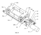
- FIG. X illustrates the product of the invention mounted on a door jamb.
- FIG. XI A illustrates the cam 20 of the invention in perspective and FIG. XI B illustrates the cam of FIG. XI A rotated about axis y—y.
- FIG. XII illustrates a motor and screw drive, as an alternative electrical actuator, connected to the cam 20 .
- surface mounted electric strike 1 comprises a housing 2 , and a cover 3 which support and protect the active components.
- the cover 3 can be in more than one piece such as 3 a and 3 b as illustrated in FIG. V. Cutout portions 5 and 6 in the housing 2 and cover 3 , respectively, are adapted to receive the bolt 7 of a door 8 .
- the cover 3 is held in place by screws 26 .
- the strike 1 is mounted on door jamb 9 using installation screws 10 a and 10 b which optionally are held in place by set screws 11 a and 11 b .
- the set screws prevent the installation screws from loosening as a result of the pounding caused by the opening and closing of the door.
- pins 30 can be employed to stabilize the installation and also prevent the early loosening of the installation screws.
- Latches 12 a and 12 b are mounted on pivots 13 a and 13 b and the latches are held in the locked position by yoke 14 .
- the yoke 14 is comprised of legs 14 a and 14 b , edge 14 c and arm 14 d having tapered edge 14 e .
- the latches are unlocked when solenoid 15 is actuated by electrical current in the conventional manner known in the art.
- solenoid 15 When the solenoid 15 is activated, shaft 16 moves in the direction of arrow 17 and the pin 18 mounted in shaft 16 causes the arm 19 of cam 20 to move in the direction of arrow 17 thereby rotating cam 20 about pin 21 .
- latches 12 a and 12 b then are free to move to open positions when one pulls on the door 8 causing the bolt 7 to be pulled out of the strike 1 .
- Latch springs 22 a and 22 b cause latches 12 a and 12 b to return to their closed positions after the bolt 7 is pulled out of the strike 1 .
- the bolt 7 retracts into the door 8 as the bolt 7 passes the latches 12 a and 12 b when the door closes.
- Electrical devices other than a solenoid can be used to lock or unlock the latches.
- an electric motor 28 and screw drive 29 can be used as illustrated in FIG. XII.
- FIGS. I–III illustrate the active components in their locked positions and FIG. IV illustrates the active components in their unlocked positions.
- shaft 16 is returned to its original position by spring 23 as best illustrated in FIG. IV.
- the yoke 14 then is returned to its locked position by lock spring 24 provided that the latches 12 a and 12 b have returned to their locked positions.
- Lock spring 24 is held in place by screw 27 .
- the yoke 14 can be pivotally mounted to housing 2 by suitable means such as screw 25 . Screw 25 is installed with sufficient clearance relative to yoke 14 to permit the yoke to freely move from a locked to an unlocked position and back while preventing the yoke from moving out of its operating position. Housing 2 , in cooperation with set screw 25 , also serves to maintain the yoke in its operating position.
- FIG. V An expanded view of the components of the invention is provided in FIG. V.
- FIGS. I–IV illustrate the strike 1 of the invention configured to operate in a fail secure mode where the door 8 is locked unless the solenoid 15 is actuated.
- the strike 1 can easily be made to work in a fail safe mode (where the door 8 is unlocked unless the solenoid 15 is actuated) by simply removing cam 20 from a first installation position, turning it upside down and reinstalling it in a second installation position.
- FIGS. VIII A and B, IX A and B and XI A and B illustrate the cam 20 in more detail with FIG. VIII A showing the cam 20 installed in the fail secure operating mode with solenoid 15 energized showing the yoke 14 in its unlocked position and FIG.
- FIG. IX A illustrates the cam 20 installed in the failsafe operating mode with solenoid 15 de-energized and the yoke in its unlocked position and FIG. IX B shows the same components with solenoid 15 energized showing the yoke in its locked position.
- FIG. XI A illustrates the cam 20 by itself in perspective and FIG. XI B illustrates the cam 20 of FIG. XI A after it has been rotated approximately 180° about axis y—y.
Landscapes
- Lock And Its Accessories (AREA)
- Special Wing (AREA)
- Closing And Opening Devices For Wings, And Checks For Wings (AREA)
- Dry Shavers And Clippers (AREA)
- Photoreceptors In Electrophotography (AREA)
- Brushes (AREA)
- Power-Operated Mechanisms For Wings (AREA)
Abstract
Description
Claims (11)
Priority Applications (7)
| Application Number | Priority Date | Filing Date | Title |
|---|---|---|---|
| US10/861,700 US7021684B2 (en) | 2004-06-04 | 2004-06-04 | Surface mounted electric strike |
| MXPA05005823A MXPA05005823A (en) | 2004-06-04 | 2005-06-01 | Surface mounted electric strike. |
| CA2509188A CA2509188C (en) | 2004-06-04 | 2005-06-03 | Surface mounted electric strike |
| EP20050253421 EP1607558B1 (en) | 2004-06-04 | 2005-06-03 | Surface mounted electric strike |
| DE200560000911 DE602005000911T2 (en) | 2004-06-04 | 2005-06-03 | Surface mounted electric strike plate |
| AT05253421T ATE360126T1 (en) | 2004-06-04 | 2005-06-03 | SURFACE MOUNTED ELECTRIC LOCK PANEL |
| ES05253421T ES2286767T3 (en) | 2004-06-04 | 2005-06-03 | ELECTRICAL SURFACE MOUNTED CLOSURE. |
Applications Claiming Priority (1)
| Application Number | Priority Date | Filing Date | Title |
|---|---|---|---|
| US10/861,700 US7021684B2 (en) | 2004-06-04 | 2004-06-04 | Surface mounted electric strike |
Publications (2)
| Publication Number | Publication Date |
|---|---|
| US20050280267A1 US20050280267A1 (en) | 2005-12-22 |
| US7021684B2 true US7021684B2 (en) | 2006-04-04 |
Family
ID=34941563
Family Applications (1)
| Application Number | Title | Priority Date | Filing Date |
|---|---|---|---|
| US10/861,700 Active 2024-10-23 US7021684B2 (en) | 2004-06-04 | 2004-06-04 | Surface mounted electric strike |
Country Status (7)
| Country | Link |
|---|---|
| US (1) | US7021684B2 (en) |
| EP (1) | EP1607558B1 (en) |
| AT (1) | ATE360126T1 (en) |
| CA (1) | CA2509188C (en) |
| DE (1) | DE602005000911T2 (en) |
| ES (1) | ES2286767T3 (en) |
| MX (1) | MXPA05005823A (en) |
Cited By (29)
| Publication number | Priority date | Publication date | Assignee | Title |
|---|---|---|---|---|
| US7185928B1 (en) * | 2005-10-11 | 2007-03-06 | Li-Shih Liao | Structure of magnetic lock |
| US7438335B1 (en) * | 2007-04-23 | 2008-10-21 | Adams Rite Manufacturing Co. | Compact electric strike with preload release capability |
| US20090056395A1 (en) * | 2007-04-23 | 2009-03-05 | Adams Rite Manufacturing Co. | Compact electric strike with preload release capability |
| US20110012709A1 (en) * | 2009-07-14 | 2011-01-20 | Compx International Inc. | Method and system for data control in electronic locks |
| US20110056253A1 (en) * | 2009-09-10 | 2011-03-10 | Compx International Inc. | Electronic latch mechanism |
| US20110074543A1 (en) * | 2009-09-29 | 2011-03-31 | Compx International Inc. | Apparatus and method for electronic access control |
| US20110181059A1 (en) * | 2010-01-27 | 2011-07-28 | Dewey David | Mode-Switchable Door Strike |
| US8047585B1 (en) * | 2007-02-14 | 2011-11-01 | Hanchett Entry Systems, Inc. | Surface mounted electric strike for releasing remote panic exit devices |
| US20120056439A1 (en) * | 2009-05-07 | 2012-03-08 | Fredrik Stendal | Adapter device |
| US20120174337A1 (en) * | 2009-08-01 | 2012-07-12 | Assa Abloy Sicherheitstechnik Gmbh | Closing device for a door |
| US20150113817A1 (en) * | 2013-10-29 | 2015-04-30 | Trine Access Technology, Inc. | Magnetically Mounted Door Hardware Template |
| US20150130195A1 (en) * | 2013-11-08 | 2015-05-14 | Li-Shih Liao | Electric lock for doors |
| US20150368958A1 (en) * | 2013-02-14 | 2015-12-24 | Eldomat Innovative Sicherheit Gmbh | Electromagnetic Door Opener |
| US9617755B2 (en) * | 2014-08-20 | 2017-04-11 | Hanchett Entry Systems, Inc. | Reinforced strike assembly |
| US20180044945A1 (en) * | 2016-08-10 | 2018-02-15 | 1 Adolfo, Llc | Electronic cathode lock |
| US20180051486A1 (en) * | 2016-08-18 | 2018-02-22 | Locway Technology Co., Ltd. (Dongguan Guangdong, CN) | Swing Bolt Lock |
| US9957733B2 (en) | 2011-09-18 | 2018-05-01 | Hanchett Entry Systems, Inc. | Access control devices of the electromagnetic lock module type |
| US20190203503A1 (en) * | 2017-12-28 | 2019-07-04 | Gianni Industries Inc. | Electric door lock device |
| US10781611B2 (en) * | 2016-07-01 | 2020-09-22 | Trine Access Technology, Inc. | Electric strike with two independent latches |
| US10988959B1 (en) * | 2020-06-17 | 2021-04-27 | Camden Marketing Inc | Rim strike assembly and methods of use |
| US20210277686A1 (en) * | 2020-03-05 | 2021-09-09 | Powertek Hardware Co., Ltd. | Electric strike lock |
| US11157789B2 (en) | 2019-02-18 | 2021-10-26 | Compx International Inc. | Medicinal dosage storage and method for combined electronic inventory data and access control |
| US11176765B2 (en) | 2017-08-21 | 2021-11-16 | Compx International Inc. | System and method for combined electronic inventory data and access control |
| US20220154491A1 (en) * | 2019-07-31 | 2022-05-19 | Camlock Systems Limited | Latching Assembly |
| US11408204B2 (en) * | 2018-04-30 | 2022-08-09 | Hanchett Entry Systems, Inc. | Electric strike for interlocking latch mechanism |
| US11542726B2 (en) * | 2019-04-05 | 2023-01-03 | Security Door Controls, Inc. | Surface mounted single solenoid electric strike |
| US11643844B2 (en) * | 2017-12-18 | 2023-05-09 | Pegasus Integrated Solutions Ltd. | Novo lock |
| US20230407676A1 (en) * | 2022-06-15 | 2023-12-21 | Hanchett Entry System, Inc. | Surface mounted electric strike |
| US11959310B2 (en) * | 2018-02-27 | 2024-04-16 | Dormakaba Canada Inc. | Strike assembly for door locking mechanism, and method of operation |
Families Citing this family (7)
| Publication number | Priority date | Publication date | Assignee | Title |
|---|---|---|---|---|
| EP1991748B1 (en) * | 2006-02-23 | 2014-12-24 | Shanghai One Top Corporation | A door strike |
| AU2007284079B2 (en) * | 2006-08-17 | 2012-04-12 | Allegion (Australia) Pty Ltd | A door strike |
| JP4961036B2 (en) * | 2007-04-05 | 2012-06-27 | デューアル メカニクス カンパニー リミテッド | Door lock device |
| WO2009043089A1 (en) * | 2007-10-02 | 2009-04-09 | Fire & Security Hardware Pty Ltd | An electronic door strike |
| CN104863418B (en) * | 2015-05-29 | 2017-08-25 | 杨帆 | A kind of door-window lockset anti-misoperation apparatus and application method |
| US11866189B2 (en) * | 2020-03-26 | 2024-01-09 | Hartwell Corporation | Latching system with movable anti-shear mechanism |
| GB2602440A (en) * | 2020-10-01 | 2022-07-06 | Linear Building Innovations Ltd | Smoke damper |
Citations (11)
| Publication number | Priority date | Publication date | Assignee | Title |
|---|---|---|---|---|
| US3211860A (en) | 1960-03-02 | 1965-10-12 | Westinghouse Electric Corp | Circuit breaker with improved trip-device enclosure |
| US3640560A (en) | 1970-08-19 | 1972-02-08 | Von Duprin Inc | Electric latch strike |
| US4626010A (en) | 1984-02-10 | 1986-12-02 | Hanchett Entry Systems, Inc. | Concealed door release mechanism |
| US4836707A (en) * | 1987-09-04 | 1989-06-06 | The United States Of America As Represented By The United States National Aeronautics And Space Administration | Releasable clamping apparatus |
| US4986584A (en) | 1988-12-22 | 1991-01-22 | Adams Rite Manufacturing Company | Electrical strike release |
| US5172945A (en) * | 1992-03-23 | 1992-12-22 | General Motors Corporation | Tri-axial support door latch |
| US5484180A (en) | 1993-06-07 | 1996-01-16 | Hanchett Entry Systems, Inc. | Electric strike mechanism |
| US5915766A (en) * | 1996-07-20 | 1999-06-29 | Kendro Laboratory Products Gmbh | Locking device |
| US6390520B1 (en) | 2000-07-10 | 2002-05-21 | Hanchett Entry Systems, Inc. | Door opener |
| US6595563B2 (en) | 2000-09-13 | 2003-07-22 | Von Duprin, Inc. | Electric strike field-selectable fail-safe/fail-secure mechanism |
| US6857671B2 (en) * | 2000-06-29 | 2005-02-22 | Paul Stefanus Millard | Locking device for a door |
Family Cites Families (1)
| Publication number | Priority date | Publication date | Assignee | Title |
|---|---|---|---|---|
| US3211850A (en) * | 1964-09-28 | 1965-10-12 | Toepfer Safe & Lock Co | Combined lock and switch |
-
2004
- 2004-06-04 US US10/861,700 patent/US7021684B2/en active Active
-
2005
- 2005-06-01 MX MXPA05005823A patent/MXPA05005823A/en active IP Right Grant
- 2005-06-03 ES ES05253421T patent/ES2286767T3/en active Active
- 2005-06-03 DE DE200560000911 patent/DE602005000911T2/en active Active
- 2005-06-03 AT AT05253421T patent/ATE360126T1/en not_active IP Right Cessation
- 2005-06-03 EP EP20050253421 patent/EP1607558B1/en active Active
- 2005-06-03 CA CA2509188A patent/CA2509188C/en active Active
Patent Citations (11)
| Publication number | Priority date | Publication date | Assignee | Title |
|---|---|---|---|---|
| US3211860A (en) | 1960-03-02 | 1965-10-12 | Westinghouse Electric Corp | Circuit breaker with improved trip-device enclosure |
| US3640560A (en) | 1970-08-19 | 1972-02-08 | Von Duprin Inc | Electric latch strike |
| US4626010A (en) | 1984-02-10 | 1986-12-02 | Hanchett Entry Systems, Inc. | Concealed door release mechanism |
| US4836707A (en) * | 1987-09-04 | 1989-06-06 | The United States Of America As Represented By The United States National Aeronautics And Space Administration | Releasable clamping apparatus |
| US4986584A (en) | 1988-12-22 | 1991-01-22 | Adams Rite Manufacturing Company | Electrical strike release |
| US5172945A (en) * | 1992-03-23 | 1992-12-22 | General Motors Corporation | Tri-axial support door latch |
| US5484180A (en) | 1993-06-07 | 1996-01-16 | Hanchett Entry Systems, Inc. | Electric strike mechanism |
| US5915766A (en) * | 1996-07-20 | 1999-06-29 | Kendro Laboratory Products Gmbh | Locking device |
| US6857671B2 (en) * | 2000-06-29 | 2005-02-22 | Paul Stefanus Millard | Locking device for a door |
| US6390520B1 (en) | 2000-07-10 | 2002-05-21 | Hanchett Entry Systems, Inc. | Door opener |
| US6595563B2 (en) | 2000-09-13 | 2003-07-22 | Von Duprin, Inc. | Electric strike field-selectable fail-safe/fail-secure mechanism |
Non-Patent Citations (1)
| Title |
|---|
| O'Leary, T: "Why Electric Strikes?", Locksmith Ledger International, Locksmith Pub. Corp., Park Bridge, IL, US, vol. 63, No. 1, Jan. 2003, pp. 3-40, 42, XP-001141526, ISSN: 1050-2254. |
Cited By (48)
| Publication number | Priority date | Publication date | Assignee | Title |
|---|---|---|---|---|
| US7185928B1 (en) * | 2005-10-11 | 2007-03-06 | Li-Shih Liao | Structure of magnetic lock |
| US8047585B1 (en) * | 2007-02-14 | 2011-11-01 | Hanchett Entry Systems, Inc. | Surface mounted electric strike for releasing remote panic exit devices |
| US8096594B2 (en) * | 2007-04-23 | 2012-01-17 | Adams Rite Manufacturing Co. | Compact electric strike with preload release capability |
| US20090056395A1 (en) * | 2007-04-23 | 2009-03-05 | Adams Rite Manufacturing Co. | Compact electric strike with preload release capability |
| US20080258481A1 (en) * | 2007-04-23 | 2008-10-23 | Adams Rite Manufacturing Co. | Compact electric strike with preload release capability |
| US7438335B1 (en) * | 2007-04-23 | 2008-10-21 | Adams Rite Manufacturing Co. | Compact electric strike with preload release capability |
| US20120056439A1 (en) * | 2009-05-07 | 2012-03-08 | Fredrik Stendal | Adapter device |
| US20110012709A1 (en) * | 2009-07-14 | 2011-01-20 | Compx International Inc. | Method and system for data control in electronic locks |
| US8970344B2 (en) | 2009-07-14 | 2015-03-03 | Compx International Inc. | Method and system for data control in electronic locks |
| US20120174337A1 (en) * | 2009-08-01 | 2012-07-12 | Assa Abloy Sicherheitstechnik Gmbh | Closing device for a door |
| US9255425B2 (en) * | 2009-08-01 | 2016-02-09 | ASSA ABLOY Sicherheitechnik GmbH | Closing device for a door |
| US20110056253A1 (en) * | 2009-09-10 | 2011-03-10 | Compx International Inc. | Electronic latch mechanism |
| US8516864B2 (en) * | 2009-09-10 | 2013-08-27 | Compx International Inc. | Electronic latch mechanism |
| US20110074543A1 (en) * | 2009-09-29 | 2011-03-31 | Compx International Inc. | Apparatus and method for electronic access control |
| US8742889B2 (en) | 2009-09-29 | 2014-06-03 | Compx International Inc. | Apparatus and method for electronic access control |
| US20110181059A1 (en) * | 2010-01-27 | 2011-07-28 | Dewey David | Mode-Switchable Door Strike |
| US8454063B2 (en) * | 2010-01-27 | 2013-06-04 | Hanchett Entry Systems, Inc. | Mode-switchable door strike |
| US10077577B2 (en) | 2011-09-18 | 2018-09-18 | Hanchett Entry Systems, Inc. | Access control devices of the electromagnetic lock module type |
| US10465421B2 (en) | 2011-09-18 | 2019-11-05 | Hanchett Entry Systems, Inc. | Access control devices of the electromagnetic lock module type |
| US9957733B2 (en) | 2011-09-18 | 2018-05-01 | Hanchett Entry Systems, Inc. | Access control devices of the electromagnetic lock module type |
| US20150368958A1 (en) * | 2013-02-14 | 2015-12-24 | Eldomat Innovative Sicherheit Gmbh | Electromagnetic Door Opener |
| US10501983B2 (en) * | 2013-02-14 | 2019-12-10 | Eldomat Innovative Sicherheit Gmbh | Electromagnetic door opener |
| EP2868845A2 (en) | 2013-10-29 | 2015-05-06 | Trine Access Technology, Inc. | Magnetically mounted door hardware templates |
| US9376835B2 (en) * | 2013-10-29 | 2016-06-28 | Trine Access Technology, Inc. | Magnetically mounted door hardware template |
| US20150113817A1 (en) * | 2013-10-29 | 2015-04-30 | Trine Access Technology, Inc. | Magnetically Mounted Door Hardware Template |
| US20150130195A1 (en) * | 2013-11-08 | 2015-05-14 | Li-Shih Liao | Electric lock for doors |
| US9702167B2 (en) * | 2013-11-08 | 2017-07-11 | Li-Shih Liao | Electric lock for doors |
| US9617755B2 (en) * | 2014-08-20 | 2017-04-11 | Hanchett Entry Systems, Inc. | Reinforced strike assembly |
| US10781611B2 (en) * | 2016-07-01 | 2020-09-22 | Trine Access Technology, Inc. | Electric strike with two independent latches |
| US20180044945A1 (en) * | 2016-08-10 | 2018-02-15 | 1 Adolfo, Llc | Electronic cathode lock |
| US10697202B2 (en) * | 2016-08-10 | 2020-06-30 | Security Door Controls | Electronic cathode lock |
| US10669747B2 (en) * | 2016-08-18 | 2020-06-02 | Locway Technology Co., Ltd. (Dongguan, Guangdong, CN) | Swing bolt lock |
| US20180051486A1 (en) * | 2016-08-18 | 2018-02-22 | Locway Technology Co., Ltd. (Dongguan Guangdong, CN) | Swing Bolt Lock |
| US11176765B2 (en) | 2017-08-21 | 2021-11-16 | Compx International Inc. | System and method for combined electronic inventory data and access control |
| US11643844B2 (en) * | 2017-12-18 | 2023-05-09 | Pegasus Integrated Solutions Ltd. | Novo lock |
| US20190203503A1 (en) * | 2017-12-28 | 2019-07-04 | Gianni Industries Inc. | Electric door lock device |
| US11959310B2 (en) * | 2018-02-27 | 2024-04-16 | Dormakaba Canada Inc. | Strike assembly for door locking mechanism, and method of operation |
| US11408204B2 (en) * | 2018-04-30 | 2022-08-09 | Hanchett Entry Systems, Inc. | Electric strike for interlocking latch mechanism |
| US11157789B2 (en) | 2019-02-18 | 2021-10-26 | Compx International Inc. | Medicinal dosage storage and method for combined electronic inventory data and access control |
| US11373078B2 (en) | 2019-02-18 | 2022-06-28 | Compx International Inc. | Medicinal dosage storage for combined electronic inventory data and access control |
| US11301741B2 (en) | 2019-02-18 | 2022-04-12 | Compx International Inc. | Medicinal dosage storage method for combined electronic inventory data and access control |
| US11542726B2 (en) * | 2019-04-05 | 2023-01-03 | Security Door Controls, Inc. | Surface mounted single solenoid electric strike |
| US20220154491A1 (en) * | 2019-07-31 | 2022-05-19 | Camlock Systems Limited | Latching Assembly |
| US11536054B2 (en) * | 2020-03-05 | 2022-12-27 | Powertek Hardware Co., Ltd. | Electric strike lock |
| US20210277686A1 (en) * | 2020-03-05 | 2021-09-09 | Powertek Hardware Co., Ltd. | Electric strike lock |
| US11549282B2 (en) * | 2020-06-17 | 2023-01-10 | Camden Marketing Inc | Rim strike assembly and methods of use |
| US10988959B1 (en) * | 2020-06-17 | 2021-04-27 | Camden Marketing Inc | Rim strike assembly and methods of use |
| US20230407676A1 (en) * | 2022-06-15 | 2023-12-21 | Hanchett Entry System, Inc. | Surface mounted electric strike |
Also Published As
| Publication number | Publication date |
|---|---|
| ES2286767T3 (en) | 2007-12-01 |
| US20050280267A1 (en) | 2005-12-22 |
| MXPA05005823A (en) | 2005-12-07 |
| EP1607558B1 (en) | 2007-04-18 |
| EP1607558A1 (en) | 2005-12-21 |
| DE602005000911T2 (en) | 2008-01-17 |
| ATE360126T1 (en) | 2007-05-15 |
| CA2509188C (en) | 2011-07-26 |
| DE602005000911D1 (en) | 2007-05-31 |
| CA2509188A1 (en) | 2005-12-04 |
Similar Documents
| Publication | Publication Date | Title |
|---|---|---|
| US7021684B2 (en) | Surface mounted electric strike | |
| US7246827B2 (en) | Fail safe/fail secure lock with quick change access window | |
| US4056276A (en) | Door lock | |
| US7980603B2 (en) | Rotating latch for latching and unlatching a door | |
| US8967679B2 (en) | Vehicle door latch | |
| US4125008A (en) | Electrically operated lock | |
| US9945153B2 (en) | Electric door strike having a dead latch release platform actuated by a spring latch keeper and a spring latch lifter feature | |
| GB2472696A (en) | An actuator controlled strike for a door latch | |
| US8333411B2 (en) | Lock mechanism | |
| US8720237B2 (en) | Rotary latch | |
| US11795737B2 (en) | Lock assembly for sliding door latch | |
| US4623178A (en) | Lock assembly | |
| CA2895850C (en) | Latch mechanism for an exit device | |
| JPS6278382A (en) | Door locking apparatus | |
| JPH08135279A (en) | Lock handle device of door used for both right and left hands | |
| US7131673B2 (en) | Electromechanical keeper | |
| EP1179108B1 (en) | Latch | |
| US11542726B2 (en) | Surface mounted single solenoid electric strike | |
| JPH0351497Y2 (en) | ||
| JPH0341016Y2 (en) | ||
| JP2002106216A (en) | Emergency lock device for door of safe or the like | |
| JPH0412352B2 (en) | ||
| KR970070394A (en) | Electronic locks for door opening and closing |
Legal Events
| Date | Code | Title | Description |
|---|---|---|---|
| AS | Assignment |
Owner name: TRINE ACCESS TECHNOLOGY, INC., NEW YORK Free format text: ASSIGNMENT OF ASSIGNORS INTEREST;ASSIGNORS:ORBETA, FERDINAND E.;SCHILDWACHTER, WILLIAM;REEL/FRAME:015761/0130 Effective date: 20040608 |
|
| STCF | Information on status: patent grant |
Free format text: PATENTED CASE |
|
| FEPP | Fee payment procedure |
Free format text: PAT HOLDER CLAIMS SMALL ENTITY STATUS, ENTITY STATUS SET TO SMALL (ORIGINAL EVENT CODE: LTOS); ENTITY STATUS OF PATENT OWNER: SMALL ENTITY |
|
| REFU | Refund |
Free format text: REFUND - PAYMENT OF MAINTENANCE FEE, 4TH YEAR, LARGE ENTITY (ORIGINAL EVENT CODE: R1551); ENTITY STATUS OF PATENT OWNER: SMALL ENTITY Free format text: REFUND - SURCHARGE FOR LATE PAYMENT, LARGE ENTITY (ORIGINAL EVENT CODE: R1554); ENTITY STATUS OF PATENT OWNER: SMALL ENTITY |
|
| FPAY | Fee payment |
Year of fee payment: 4 |
|
| SULP | Surcharge for late payment | ||
| FPAY | Fee payment |
Year of fee payment: 8 |
|
| MAFP | Maintenance fee payment |
Free format text: PAYMENT OF MAINTENANCE FEE, 12TH YR, SMALL ENTITY (ORIGINAL EVENT CODE: M2553) Year of fee payment: 12 |