US7017357B2 - Emergency power generation system - Google Patents
Emergency power generation system Download PDFInfo
- Publication number
- US7017357B2 US7017357B2 US10/716,301 US71630103A US7017357B2 US 7017357 B2 US7017357 B2 US 7017357B2 US 71630103 A US71630103 A US 71630103A US 7017357 B2 US7017357 B2 US 7017357B2
- Authority
- US
- United States
- Prior art keywords
- compressor
- set forth
- refrigerant
- air
- flow
- Prior art date
- Legal status (The legal status is an assumption and is not a legal conclusion. Google has not performed a legal analysis and makes no representation as to the accuracy of the status listed.)
- Active, expires
Links
Images


Classifications
-
- F—MECHANICAL ENGINEERING; LIGHTING; HEATING; WEAPONS; BLASTING
- F25—REFRIGERATION OR COOLING; COMBINED HEATING AND REFRIGERATION SYSTEMS; HEAT PUMP SYSTEMS; MANUFACTURE OR STORAGE OF ICE; LIQUEFACTION SOLIDIFICATION OF GASES
- F25B—REFRIGERATION MACHINES, PLANTS OR SYSTEMS; COMBINED HEATING AND REFRIGERATION SYSTEMS; HEAT PUMP SYSTEMS
- F25B1/00—Compression machines, plants or systems with non-reversible cycle
-
- F—MECHANICAL ENGINEERING; LIGHTING; HEATING; WEAPONS; BLASTING
- F01—MACHINES OR ENGINES IN GENERAL; ENGINE PLANTS IN GENERAL; STEAM ENGINES
- F01K—STEAM ENGINE PLANTS; STEAM ACCUMULATORS; ENGINE PLANTS NOT OTHERWISE PROVIDED FOR; ENGINES USING SPECIAL WORKING FLUIDS OR CYCLES
- F01K25/00—Plants or engines characterised by use of special working fluids, not otherwise provided for; Plants operating in closed cycles and not otherwise provided for
- F01K25/08—Plants or engines characterised by use of special working fluids, not otherwise provided for; Plants operating in closed cycles and not otherwise provided for using special vapours
-
- F—MECHANICAL ENGINEERING; LIGHTING; HEATING; WEAPONS; BLASTING
- F25—REFRIGERATION OR COOLING; COMBINED HEATING AND REFRIGERATION SYSTEMS; HEAT PUMP SYSTEMS; MANUFACTURE OR STORAGE OF ICE; LIQUEFACTION SOLIDIFICATION OF GASES
- F25B—REFRIGERATION MACHINES, PLANTS OR SYSTEMS; COMBINED HEATING AND REFRIGERATION SYSTEMS; HEAT PUMP SYSTEMS
- F25B1/00—Compression machines, plants or systems with non-reversible cycle
- F25B1/04—Compression machines, plants or systems with non-reversible cycle with compressor of rotary type
-
- F—MECHANICAL ENGINEERING; LIGHTING; HEATING; WEAPONS; BLASTING
- F25—REFRIGERATION OR COOLING; COMBINED HEATING AND REFRIGERATION SYSTEMS; HEAT PUMP SYSTEMS; MANUFACTURE OR STORAGE OF ICE; LIQUEFACTION SOLIDIFICATION OF GASES
- F25B—REFRIGERATION MACHINES, PLANTS OR SYSTEMS; COMBINED HEATING AND REFRIGERATION SYSTEMS; HEAT PUMP SYSTEMS
- F25B2400/00—General features or devices for refrigeration machines, plants or systems, combined heating and refrigeration systems or heat-pump systems, i.e. not limited to a particular subgroup of F25B
- F25B2400/14—Power generation using energy from the expansion of the refrigerant
- F25B2400/141—Power generation using energy from the expansion of the refrigerant the extracted power is not recycled back in the refrigerant circuit
Definitions
- This invention relates generally to heating and air conditioning systems and, more particularly, to a method and apparatus for operating such systems in an emergency power generating mode.
- a common arrangement of a comfort system for a residence or small business is the combination of an air conditioning and heating system with an evaporator coil, such as a so called A-coil, mounted in the top portion of a furnace such that the single blower can be used to alternatively circulate the air to be conditioned over a furnace heat exchanger or over the evaporator coil and then further distributed to the spaces to be heated or cooled.
- an evaporator coil such as a so called A-coil
- the air conditioning system is activated with the compressor operating in reverse as an expander.
- the compressor/expander can operate in an organic rankine cycle to drive a generator to provide emergency power to the various components requiring power to operate.
- provision is made to selectively change the flow of refrigerant from the low pressure side of the compressor/expander for use in a cooling mode, to the high pressure side thereof for use in an emergency power mode.
- provision is made to interconnect the condenser to either the low or the high pressure side of the compressor/expander to facilitate the respective emergency power and cooling modes.
- FIG. 1 is a schematic illustration of a combined hot air furnace and air conditioning system as operating in the heating mode in accordance with the prior art.
- FIG. 2 is a schematic illustration of a combined hot air furnace and air conditioning system as operating in the cooling mode in accordance with the prior art.
- FIG. 3 is a schematic illustration of a combined hot air furnace and air conditioning system as operating in an emergency power mode in accordance with a preferred embodiment of the invention.
- FIG. 4 is a schematic illustration of an air conditioning system operating in the cooling mode in accordance with the prior art.
- FIG. 5 is a schematic illustration of an air conditioning system as operating in an emergency power mode in accordance with a preferred embodiment of the invention.
- FIG. 6 is a schematic illustration of an air conditioning system as modified for emergency power capabilities in accordance with a preferred embodiment of the invention.
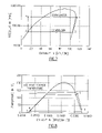
- FIG. 7 is a PH diagram of a recuperated organic rankine cycle in accordance with a preferred embodiment of the invention.
- FIG. 8 is a TS diagram of a recuperated organic rankine cycle in accordance with a preferred embodiment of the invention.
- FIGS. 1 and 2 there is shown a typical comfort system of the type found in a residence or small business, comprising a furnace 11 having a heat exchanger 12 in the lower end thereof and an air conditioner evaporator coil 13 in the upper end thereof.
- a blower 14 is provided to bring air in from the space being conditioned, pass it through the furnace 11 and supply the heated or cooled air to a supply air duct 16 for distribution within the space to be conditioned.
- the furnace is turned off and the heat exchanger 12 , while remaining in the air flow stream from the blower 14 , does not in any way contribute to the conditioning of the air passing through the furnace 11 .
- the evaporator coil 13 which is operatively connected within an air conditioning circuit as shown in FIG. 4 , has a relatively high pressure refrigerant such as R-22 or R-134a, being passed therethrough to provide a cooling effect to the air being circulated thereover.
- R-22 or R-134a relatively high pressure refrigerant
- an activation control 21 which receive temporary emergency power from a battery 20 , is provided to selectively activate the furnace 22 and/or the air conditioner 23 to provide heating or cooling or, by simultaneously activating the furnace 22 and the air conditioner 23 , it can provide both heating and emergency power to operate the subsystems and other appliances.
- the activation control turns on the furnace 22 so as to function in the manner described with respect to FIG. 1 .
- the activation control 21 turns on the air conditioner 23 so as to function in the manner described in respect to FIG. 2 hereof.
- the air conditioning circuit as shown in FIG. 4 includes, in addition to the evaporator 13 as described hereinabove, the compressor 24 driven by a motor 26 , with the motor 26 being turned on or off by the activation control 21 .
- the compressor receives refrigerant vapor from the evaporator 13 at its low pressure side and discharges higher pressure refrigerant from its high pressure side to a condenser 27 . After the condenser causes the refrigerant to condense to a liquid, the liquid is passed to an expansion valve or throttle valve 28 , and the throttle valve is selectively operated in order to control the flow of refrigerant into the evaporator 13 .
- the hot air furnace/air conditioning system is operated as shown in FIG. 3 a , with the activation control 21 turning on both the furnace 22 and the air conditioner 23 .
- the air conditioner system 23 rather then operating as shown in its cooling mode as set forth in FIG. 4 , is operated as an organic rankine cycle as shown in FIG. 5 .
- the evaporator 13 and condenser 27 operate in a similar manner as described hereinabove with respect to the cooling mode of operation.
- the compressor 24 and its drive motor 26 on the other hand operate substantially differently when in the emergency power mode of operation.
- the refrigerant passes into the low pressure side of the compressor and exiting from the high pressure side thereof as shown in FIG. 4 , the refrigerant is passed to the high pressure side of the compressor (now acting as a turbine) and exits from the low pressure side thereof, with the lower pressure refrigerant then passing to the condenser 27 .
- the motor 26 (which now operates as a generator) is driven by the expander to generate electricity for purposes of providing power to the blower 14 , the ignitor 18 , and the inducer 19 , as well as to other appliances such as a refrigerator and/or freezer.
- Suitable types of compressors that are commonly used in air conditioning systems and which can be effectively used in reverse as turbines include scroll compressors and screw compressors.
- the pump 29 In order for the system to operate as shown in FIG. 5 , it is necessary to add another component i.e. the pump 29 in order to pump condensate from the condenser 27 to the evaporator 13 .
- the power generated by the generator 26 also provides power to the pump 29 .
- a typical temperature of the air passing over the evaporator 13 is 75°, and the temperature of the air passing over the condenser is 100° F.
- the heated air passing over the evaporator 13 is 140° F.
- the temperature of the air passing over the outdoor condenser is 10° F.
- the temperature of the air passing over the evaporator coil 13 is 140° F., but after using the energy of that heated air to drive the organic rankine cycle system as shown in FIG. 5 the temperature of the air is lowered to 130° F. However, this is still substantially above the temperature of the air in the space to be heated and will be sufficient to heat the space under emergency conditions.
- the flow control apparatus 31 In order to convert the operation of the air conditioning unit 23 from that of the cooling mode as shown in FIG. 4 to the emergency power mode as shown in FIG. 5 it is necessary to activate the flow control apparatus 31 as shown in FIG. 3 b .
- the flow control apparatus 31 simultaneously changes the flow into and out of the compressor/turbine as described hereinabove in respective FIG. 4 and FIG. 5 , as well as bypassing the throttle valve 28 in favor of the pump 29 . This can be accomplished by way of the insertion of the three way valves 32 , 33 , 34 and 36 as shown in FIG. 6 .
- the three way valve 32 is selectively operated to cause the flow of refrigerant from the evaporator 13 to either the low pressure side of the compressor/turbine for purposes of cooling mode operation, or to the high pressure side thereof for emergency power mode operation.
- the three way valve 33 is selectively operated to connect the low pressure side of the compressor/turbine 24 to the condenser 27 for emergency power mode operation or the high pressure side thereof to the condenser 27 for cooling mode operation.
- the three way valves 34 and 36 are operated to selectively direct the refrigerant flow through the expansion valve 28 during cooling mode operation or through the pump 29 during emergency power mode operation.
- the compressor/turbine will either be driven by the motor/generator or will drive the motor/generator to produce power as described hereinabove.
- FIGS. 7 and 8 there is shown the thermodynamic calculations of the disclosed emergency power generation system during a typical winter day.
- FIG. 7 shows a pressure-enthalpy diagram of the system, indicating condenser and evaporator pressures when using an air conditioner with R-22 as refrigerant as a function of enthalpy.
- FIG. 8 shows the corresponding temperature-entropy diagram indicating condenser and evaporator saturation temperatures as a function of entropy.
- the process shown in FIGS. 7 and 8 follows a clockwise cycle (opposite from the counterclockwise air conditioning cycle). Starting at state point 1 , the inlet of the expander, high-pressure hot refrigerant vapor expands from high pressure to low pressure when giving off its energy to the expander.
- State point 2 After reaching the expander outlet (state point 2 ) the low pressure/low temperature refrigerant is de-superheated and liquefied in the condenser.
- State point 3 is the condenser exit where the liquified refrigerant has a low temperature and low pressure. A pump will not increase the pressure of the refrigerant without any measurable increase in temperature. The pump exit is state point 4 .
- the thermodynamic cycle is completed after the high pressure liquid is vaporized in the evaporator from where the high pressure high temperature vapor will enter state point 1 again.
Landscapes
- Engineering & Computer Science (AREA)
- Mechanical Engineering (AREA)
- General Engineering & Computer Science (AREA)
- Physics & Mathematics (AREA)
- Thermal Sciences (AREA)
- Chemical & Material Sciences (AREA)
- Combustion & Propulsion (AREA)
- Air Conditioning Control Device (AREA)
Abstract
In a comfort system having a combination furnace and air conditioner, the two are operated simultaneously at periods of time in which emergency power is desired, with the air conditioning system being temporarily converted to cause the flow of refrigerant to pass from the evaporator to a high pressure side of said compressor rather than to the low pressure side thereof to thereby drive the compressor in reverse such that it operates as a turbine. The turbine then drives its motor in reverse to generate power to be supplied to the various components of the systems and to other appliances during emergency mode operation.
Description
This invention relates generally to heating and air conditioning systems and, more particularly, to a method and apparatus for operating such systems in an emergency power generating mode.
Power outages during the winter season due to severe weather, such as snow storms or freezing rain, have forced many residences and businesses to install additional emergency power equipment e.g. emergency generators and or batteries, in order to at least supply the power for essentials such as emergency lighting, heat (power to the furnace fan and controls), and for a refrigerator and freezer. These emergency power accommodations need to be permanently interconnected into the various components requiring power or interconnected when the power failure occurs and disconnected when power has been resumed. In either case, a substantial expense needs to be incurred in order to provide the necessary equipment which is seldom used.
A common arrangement of a comfort system for a residence or small business is the combination of an air conditioning and heating system with an evaporator coil, such as a so called A-coil, mounted in the top portion of a furnace such that the single blower can be used to alternatively circulate the air to be conditioned over a furnace heat exchanger or over the evaporator coil and then further distributed to the spaces to be heated or cooled. When a system is operating in the heating mode, the evaporator coil is disposed within the air flow path but is not active. Similarly, when operating in the cooling mode, the furnace heat exchanger lies within a path of the air being circulated by the fan, but the furnace heat exchanger is not heated.
Briefly, in accordance with one aspect of the invention, during periods in which the heating function is desired but the normal power accommodation is not available, the air conditioning system is activated with the compressor operating in reverse as an expander. In this way, the compressor/expander can operate in an organic rankine cycle to drive a generator to provide emergency power to the various components requiring power to operate.
By yet another aspect of the invention, provision is made to selectively change the flow of refrigerant from the low pressure side of the compressor/expander for use in a cooling mode, to the high pressure side thereof for use in an emergency power mode. Similarly, provision is made to interconnect the condenser to either the low or the high pressure side of the compressor/expander to facilitate the respective emergency power and cooling modes.
By yet another aspect of the invention, provision is made to selectively provide either an expansion valve or a pump to facilitate the flow of refrigerant from the condenser to the evaporator for the respective operations in the cooling or emergency power modes.
In the drawings as hereinafter described, a preferred embodiment is depicted; however, various other modifications and alternate constructions can be made thereto without departing from the true spirt and scope of the invention.
Referring now to FIGS. 1 and 2 , there is shown a typical comfort system of the type found in a residence or small business, comprising a furnace 11 having a heat exchanger 12 in the lower end thereof and an air conditioner evaporator coil 13 in the upper end thereof. A blower 14 is provided to bring air in from the space being conditioned, pass it through the furnace 11 and supply the heated or cooled air to a supply air duct 16 for distribution within the space to be conditioned.
As shown in FIG. 1 , during heating operation, fuel and air are introduced to a burner 17 with the combination being ignited by an ignitor 18 so as to introduce hot combustion gases into the heat exchanger 12. The gases are drawn up through the heat exchanger 12 by an inducer 19, with the flue gas being then discharged to the atmosphere. The blower 14, in turn, circulates air over the heat exchanger 12 where it is heated to around 140° F. as it passes to the supply air duct 16. Although the evaporator coil 13 remains within the air flow stream, it has no effect on the conditioning of the air passing thereover.
During the cooling mode of operation, as shown in FIG. 2 , the furnace is turned off and the heat exchanger 12, while remaining in the air flow stream from the blower 14, does not in any way contribute to the conditioning of the air passing through the furnace 11. The evaporator coil 13, which is operatively connected within an air conditioning circuit as shown in FIG. 4 , has a relatively high pressure refrigerant such as R-22 or R-134a, being passed therethrough to provide a cooling effect to the air being circulated thereover. Thus, the 75° F. return air from the blower 14, when passed over the evaporator coil 13, is cooled to 55° F. prior to being passed to the supply air duct 16.
As shown in FIGS. 3 a and 3 b an activation control 21 which receive temporary emergency power from a battery 20, is provided to selectively activate the furnace 22 and/or the air conditioner 23 to provide heating or cooling or, by simultaneously activating the furnace 22 and the air conditioner 23, it can provide both heating and emergency power to operate the subsystems and other appliances.
When only operation of the furnace 22 is desired during low temperature ambient conditions, the activation control turns on the furnace 22 so as to function in the manner described with respect to FIG. 1 .
When only the air conditioning mode of operation is desired during higher temperature ambient conditions, the activation control 21 turns on the air conditioner 23 so as to function in the manner described in respect to FIG. 2 hereof. In that case, the air conditioning circuit as shown in FIG. 4 includes, in addition to the evaporator 13 as described hereinabove, the compressor 24 driven by a motor 26, with the motor 26 being turned on or off by the activation control 21. The compressor receives refrigerant vapor from the evaporator 13 at its low pressure side and discharges higher pressure refrigerant from its high pressure side to a condenser 27. After the condenser causes the refrigerant to condense to a liquid, the liquid is passed to an expansion valve or throttle valve 28, and the throttle valve is selectively operated in order to control the flow of refrigerant into the evaporator 13.
During periods in which the normal power source is incapacitated, and when it is desired to operate the furnace 22 to supply at least some heat to the supply air duct 16, the hot air furnace/air conditioning system is operated as shown in FIG. 3 a, with the activation control 21 turning on both the furnace 22 and the air conditioner 23. However, the air conditioner system 23 rather then operating as shown in its cooling mode as set forth in FIG. 4 , is operated as an organic rankine cycle as shown in FIG. 5 . Here, the evaporator 13 and condenser 27 operate in a similar manner as described hereinabove with respect to the cooling mode of operation. The compressor 24 and its drive motor 26, on the other hand operate substantially differently when in the emergency power mode of operation. Rather then the refrigerant passing into the low pressure side of the compressor and exiting from the high pressure side thereof as shown in FIG. 4 , the refrigerant is passed to the high pressure side of the compressor (now acting as a turbine) and exits from the low pressure side thereof, with the lower pressure refrigerant then passing to the condenser 27. With the compressor/turbine acting as an expander, the motor 26 (which now operates as a generator) is driven by the expander to generate electricity for purposes of providing power to the blower 14, the ignitor 18, and the inducer 19, as well as to other appliances such as a refrigerator and/or freezer.
Suitable types of compressors that are commonly used in air conditioning systems and which can be effectively used in reverse as turbines include scroll compressors and screw compressors.
In order for the system to operate as shown in FIG. 5 , it is necessary to add another component i.e. the pump 29 in order to pump condensate from the condenser 27 to the evaporator 13. The power generated by the generator 26 also provides power to the pump 29.
It should be recognized that, even though the compressor/turbine and the motor/generator operate in opposite directions for the respective cooling mode and emergency power mode, the flow of refrigerant is in the same direction for the two modes of operation. This is in contrast to a heat pump operation wherein a condenser and evaporator change roles with the transition from heating and cooling modes. In this regard, it should be recognized that the difference in ambient conditions causes the condenser during the cooling season to be at a higher pressure than the evaporator but at a lower pressure during winter organic rankine cycle mode of operation. That is, during a cooling mode of operation, a typical temperature of the air passing over the evaporator 13 is 75°, and the temperature of the air passing over the condenser is 100° F., whereas during winter ORC mode of operation, the heated air passing over the evaporator 13 is 140° F., and the temperature of the air passing over the outdoor condenser is 10° F.
As will be seen in FIG. 3 a, during operation in the emergency power mode, with both the furnace 22 and the air conditioner 23 operating (but in the emergency power mode as shown in FIG. 5 ), the temperature of the air passing over the evaporator coil 13 is 140° F., but after using the energy of that heated air to drive the organic rankine cycle system as shown in FIG. 5 the temperature of the air is lowered to 130° F. However, this is still substantially above the temperature of the air in the space to be heated and will be sufficient to heat the space under emergency conditions.
In order to convert the operation of the air conditioning unit 23 from that of the cooling mode as shown in FIG. 4 to the emergency power mode as shown in FIG. 5 it is necessary to activate the flow control apparatus 31 as shown in FIG. 3 b. The flow control apparatus 31 simultaneously changes the flow into and out of the compressor/turbine as described hereinabove in respective FIG. 4 and FIG. 5 , as well as bypassing the throttle valve 28 in favor of the pump 29. This can be accomplished by way of the insertion of the three way valves 32, 33, 34 and 36 as shown in FIG. 6 . Thus, the three way valve 32 is selectively operated to cause the flow of refrigerant from the evaporator 13 to either the low pressure side of the compressor/turbine for purposes of cooling mode operation, or to the high pressure side thereof for emergency power mode operation. Similarly, the three way valve 33 is selectively operated to connect the low pressure side of the compressor/turbine 24 to the condenser 27 for emergency power mode operation or the high pressure side thereof to the condenser 27 for cooling mode operation.
In a similar manner, the three way valves 34 and 36 are operated to selectively direct the refrigerant flow through the expansion valve 28 during cooling mode operation or through the pump 29 during emergency power mode operation. Depending on the mode of operation, the compressor/turbine will either be driven by the motor/generator or will drive the motor/generator to produce power as described hereinabove.
Referring now to FIGS. 7 and 8 there is shown the thermodynamic calculations of the disclosed emergency power generation system during a typical winter day. FIG. 7 shows a pressure-enthalpy diagram of the system, indicating condenser and evaporator pressures when using an air conditioner with R-22 as refrigerant as a function of enthalpy. FIG. 8 shows the corresponding temperature-entropy diagram indicating condenser and evaporator saturation temperatures as a function of entropy. The process shown in FIGS. 7 and 8 follows a clockwise cycle (opposite from the counterclockwise air conditioning cycle). Starting at state point 1, the inlet of the expander, high-pressure hot refrigerant vapor expands from high pressure to low pressure when giving off its energy to the expander. After reaching the expander outlet (state point 2) the low pressure/low temperature refrigerant is de-superheated and liquefied in the condenser. State point 3 is the condenser exit where the liquified refrigerant has a low temperature and low pressure. A pump will not increase the pressure of the refrigerant without any measurable increase in temperature. The pump exit is state point 4. The thermodynamic cycle is completed after the high pressure liquid is vaporized in the evaporator from where the high pressure high temperature vapor will enter state point 1 again.
Assuming realistic pump and expander efficiencies and traditional HVAC heat exchanger heat transfer rates and pressure line losses, there calculations show that a 3.5 ton residential air conditioning unit when operating in reverse as an emergency power generation system can generate a net power of 75 Watts. This power is sufficient for the auxiliary equipment of the furnace (fans/pumps/controls) as well as residential refrigeration equipment and some emergency lighting, thereby proving the technical viability of the disclosed invention.
While the present invention has been particularly shown and described with reference to preferred and alternate embodiments as illustrated in the drawings, it will be understood by one skilled in the art that various changes in detail may be effected therein without departing from the spirit and scope of the invention as defined by the claims.
Claims (15)
1. A comfort system for heating or cooling air by the selective circulation of air over a furnace heat exchanger or over an air conditioning evaporator coil comprising:
a heating system for circulating hot gases through the heat exchanger;
an air conditioning system for circulating refrigerant through an evaporator coil, a compressor, a condenser and an expansion valve;
an activation control for simultaneously operating said heating and air conditioning systems to cause a combined heating of the air circulated thereover; and
flow control apparatus for causing the flow of refrigerant to pass from said evaporator to a high pressure side of said compressor such that said compressor is driven in reverse to function as a turbine.
2. A comfort system as set forth in claim 1 wherein said compressor is a motor driven compressor and further wherein when said compressor is made to operate in reverse, said compressor functions to drive said motor in reverse to generate power.
3. A comfort system as set forth in claim 1 wherein said compressor is a scroll compressor.
4. A comfort system as set forth in claim 1 wherein said compressor is a screw compressor.
5. A comfort system as set forth in claim 1 and including a pump for circulating refrigerant from said condenser to said evaporator.
6. A comfort system as set forth in claim 1 wherein said flow control apparatus includes valve means for conducting the flow of refrigerant from a low pressure side of said compressor to said condenser.
7. A comfort system as set forth in claim 1 wherein flow control apparatus includes valve means for conducting the flow of refrigerant from said condenser to a pump.
8. A comfort system as set forth in claim 1 wherein said flow control apparatus includes valve means for conducting the flow of refrigerant of a pump to said evaporator.
9. A comfort system as set forth in claim 1 wherein said flow control apparatus includes at least one three way valve.
10. A comfort system as set forth in claim 1 wherein said activation control also includes a battery.
11. A method operating a comfort system having a heating system and a cooling system, the heating system having a heat exchanger through which hot gases are circulated and over which air is circulated to be heated, and the cooling system having in serial flow relationship a motor driven compressor, a condenser, an expansion valve and an evaporator coil, said heat exchanger and said evaporator coil both being in the path of the circulated air, comprising the steps of:
causing said comfort system to operate such that circulated air passes over both said heat exchanger to be heated and over said evaporator coil; and
changing the flow of refrigerant into said compressor from a low pressure side thereof to a high pressure side thereof so as to cause it to operate in reverse as a turbine.
12. A method as set forth in claim 11 and including the step of providing a pump to circulate refrigerant from said condenser to said evaporator coil.
13. A method as set forth in claim 11 wherein said compressor is motor driven and further wherein the step of causing said compressor to operate in reverse also causes said compressor to drive said motor in reverse such that said motor functions as a generator.
14. A method as set forth in claim 11 wherein said compressor is a scroll compressor.
15. A method as set forth in claim 11 wherein said compressor is a screw compressor.
Priority Applications (1)
| Application Number | Priority Date | Filing Date | Title |
|---|---|---|---|
| US10/716,301 US7017357B2 (en) | 2003-11-18 | 2003-11-18 | Emergency power generation system |
Applications Claiming Priority (1)
| Application Number | Priority Date | Filing Date | Title |
|---|---|---|---|
| US10/716,301 US7017357B2 (en) | 2003-11-18 | 2003-11-18 | Emergency power generation system |
Publications (2)
| Publication Number | Publication Date |
|---|---|
| US20050103465A1 US20050103465A1 (en) | 2005-05-19 |
| US7017357B2 true US7017357B2 (en) | 2006-03-28 |
Family
ID=34574393
Family Applications (1)
| Application Number | Title | Priority Date | Filing Date |
|---|---|---|---|
| US10/716,301 Active 2024-06-28 US7017357B2 (en) | 2003-11-18 | 2003-11-18 | Emergency power generation system |
Country Status (1)
| Country | Link |
|---|---|
| US (1) | US7017357B2 (en) |
Cited By (16)
| Publication number | Priority date | Publication date | Assignee | Title |
|---|---|---|---|---|
| US20060124079A1 (en) * | 1999-12-17 | 2006-06-15 | Satnarine Singh | System and method for recovering wasted energy from an internal combustion engine |
| US20080092539A1 (en) * | 2006-10-23 | 2008-04-24 | Southwest Research Institute | System And Method For Cooling A Combustion Gas Charge |
| US20080289334A1 (en) * | 2007-05-08 | 2008-11-27 | Matt Orosz | Solar collection and conversion system and methods and apparatus for control thereof |
| US20090261678A1 (en) * | 2008-04-17 | 2009-10-22 | Sortore Christopher K | High-Speed Permanent Magnet Motor and Generator with Low-Loss Metal Rotor |
| US20090284011A1 (en) * | 2008-05-16 | 2009-11-19 | Mcbride Thomas S | Continuos-Absorption Turbine |
| US20100005831A1 (en) * | 2007-02-02 | 2010-01-14 | Carrier Corporation | Enhanced refrigerant system |
| US20100031677A1 (en) * | 2007-03-16 | 2010-02-11 | Alexander Lifson | Refrigerant system with variable capacity expander |
| US20100327687A1 (en) * | 2009-06-24 | 2010-12-30 | Victor Iannello | Systems, Devices, and/or Methods for Managing Magnetic Bearings |
| US20110023508A1 (en) * | 2005-10-05 | 2011-02-03 | American Power Conversion Corporation | Sub-cooling unit for cooling system and method |
| US20110030398A1 (en) * | 2009-08-10 | 2011-02-10 | Emerson Electric Co. | Inhibiting Compressor Backspin Via a Condenser Motor |
| US20110179792A1 (en) * | 2008-06-23 | 2011-07-28 | Norbert Pieper | Steam power unit |
| US8330311B2 (en) | 2008-04-18 | 2012-12-11 | Dresser-Rand Company | Magnetic thrust bearing with integrated electronics |
| US20130000344A1 (en) * | 2009-02-19 | 2013-01-03 | Emerson Network Power Co., Ltd. | Air conditioner |
| US8987959B2 (en) | 2010-06-23 | 2015-03-24 | Dresser-Rand Company | Split magnetic thrust bearing |
| US20170038081A1 (en) * | 2015-08-07 | 2017-02-09 | Patrick Lai | Air-treatment apparatus for use with building |
| US20180119578A1 (en) * | 2016-11-01 | 2018-05-03 | Ford Global Technologies, Llc | Waste heat recovery for power generation and engine warm up |
Families Citing this family (12)
| Publication number | Priority date | Publication date | Assignee | Title |
|---|---|---|---|---|
| US20170080773A1 (en) | 2008-11-03 | 2017-03-23 | Arkema France | Vehicle Heating and/or Air Conditioning Method |
| WO2011038131A2 (en) * | 2009-09-23 | 2011-03-31 | Brightearth Technologies, Inc. | System for underwater compressed fluid energy storage and method of deploying same |
| DK177468B1 (en) * | 2010-09-28 | 2013-06-24 | Innogie Aps | Fully integrated solar absorber |
| EP2538040B1 (en) * | 2011-06-22 | 2016-10-05 | Orcan Energy AG | Combined heat and power device and associated method |
| WO2014020770A1 (en) * | 2012-08-03 | 2014-02-06 | 株式会社島津製作所 | Turbine compressor device, turbine compressor system, and aircraft ventilation system |
| US8763398B1 (en) * | 2013-08-07 | 2014-07-01 | Kalex, Llc | Methods and systems for optimizing the performance of rankine power system cycles |
| US9267702B2 (en) * | 2013-09-24 | 2016-02-23 | Claudio Santini | Adjustable transition for accessing box coils |
| CN105016411B (en) * | 2015-07-08 | 2017-03-29 | 攀钢集团攀枝花钢钒有限公司 | Waste water evaporation concentration system and waste water evaporating concentrating method |
| US9845998B2 (en) * | 2016-02-03 | 2017-12-19 | Sten Kreuger | Thermal energy storage and retrieval systems |
| US10285310B2 (en) * | 2016-03-20 | 2019-05-07 | Robert Bonar | Computer data center cooling and electricity generation using recovered heat |
| US20210123607A1 (en) * | 2019-10-28 | 2021-04-29 | Carrier Corporation | Thermally enhanced heating |
| DE102019130215A1 (en) * | 2019-11-08 | 2021-05-12 | Technische Universität Dresden | Device for generating electrical energy from waste heat and for conditioning air as well as method for operating the device |
Citations (65)
| Publication number | Priority date | Publication date | Assignee | Title |
|---|---|---|---|---|
| JPS5246244A (en) | 1975-10-08 | 1977-04-12 | Ishikawajima Harima Heavy Ind Co Ltd | Waste heat recovery system |
| JPS5445419A (en) | 1977-09-16 | 1979-04-10 | Ishikawajima Harima Heavy Ind Co Ltd | Waste heat retrievable process in internal combustion engine |
| JPS5460634A (en) | 1977-10-24 | 1979-05-16 | Agency Of Ind Science & Technol | Lubrication of turbine of rankine cycle engine |
| JPS5591711A (en) | 1978-12-28 | 1980-07-11 | Matsushita Electric Ind Co Ltd | Rankine cycle apparatus |
| JPS5888409A (en) | 1981-11-20 | 1983-05-26 | Komatsu Ltd | Ranking bottoming device of diesel engine |
| US4386499A (en) | 1980-11-24 | 1983-06-07 | Ormat Turbines, Ltd. | Automatic start-up system for a closed rankine cycle power plant |
| JPS58122308A (en) | 1982-01-18 | 1983-07-21 | Mitsui Eng & Shipbuild Co Ltd | Method and equipment for heat storage operation of waste heat recovery rankine cycle system |
| JPS5943928A (en) | 1982-09-03 | 1984-03-12 | Toshiba Corp | Gas turbine generator |
| JPS5954712A (en) | 1982-09-24 | 1984-03-29 | Nippon Denso Co Ltd | Rankine cycle oil return system |
| JPS5963310A (en) | 1982-04-23 | 1984-04-11 | Hitachi Ltd | Compound plant |
| JPS59138707A (en) | 1983-01-28 | 1984-08-09 | Hitachi Ltd | Rankine engine |
| JPS59158303A (en) | 1983-02-28 | 1984-09-07 | Hitachi Ltd | Circulation control method and system |
| JPS60158561A (en) | 1984-01-27 | 1985-08-19 | Hitachi Ltd | Fuel cell-thermal power generating complex system |
| US4590384A (en) | 1983-03-25 | 1986-05-20 | Ormat Turbines, Ltd. | Method and means for peaking or peak power shaving |
| US4617808A (en) | 1985-12-13 | 1986-10-21 | Edwards Thomas C | Oil separation system using superheat |
| US4760705A (en) | 1983-05-31 | 1988-08-02 | Ormat Turbines Ltd. | Rankine cycle power plant with improved organic working fluid |
| US4901531A (en) | 1988-01-29 | 1990-02-20 | Cummins Engine Company, Inc. | Rankine-diesel integrated system |
| US5038567A (en) | 1989-06-12 | 1991-08-13 | Ormat Turbines, Ltd. | Method of and means for using a two-phase fluid for generating power in a rankine cycle power plant |
| US5119635A (en) | 1989-06-29 | 1992-06-09 | Ormat Turbines (1965) Ltd. | Method of a means for purging non-condensable gases from condensers |
| JPH0688523A (en) | 1992-09-08 | 1994-03-29 | Toyota Motor Corp | Waste heat recovery system |
| US5339632A (en) | 1992-12-17 | 1994-08-23 | Mccrabb James | Method and apparatus for increasing the efficiency of internal combustion engines |
| US5598706A (en) | 1993-02-25 | 1997-02-04 | Ormat Industries Ltd. | Method of and means for producing power from geothermal fluid |
| US5632143A (en) | 1994-06-14 | 1997-05-27 | Ormat Industries Ltd. | Gas turbine system and method using temperature control of the exhaust gas entering the heat recovery cycle by mixing with ambient air |
| US5640842A (en) | 1995-06-07 | 1997-06-24 | Bronicki; Lucien Y. | Seasonally configurable combined cycle cogeneration plant with an organic bottoming cycle |
| JPH09170405A (en) * | 1995-12-18 | 1997-06-30 | Ishikawajima Harima Heavy Ind Co Ltd | Pressurized fluidized bed compound power generation facility |
| US5664419A (en) | 1992-10-26 | 1997-09-09 | Ormat Industries Ltd | Method of and apparatus for producing power using geothermal fluid |
| DE19630559A1 (en) | 1996-07-19 | 1998-01-22 | Reschberger Stefan | Device for using energy of heating system of households |
| WO1998006791A1 (en) | 1996-08-14 | 1998-02-19 | Alliedsignal Inc. | Pentafluoropropanes and hexafluoropropanes as working fluids for power generation |
| US5761921A (en) | 1996-03-14 | 1998-06-09 | Kabushiki Kaisha Toshiba | Air conditioning equipment |
| DE19650183A1 (en) * | 1996-12-04 | 1998-06-10 | Mueller Herbert Prof Dr Ing Ha | Method for utilising high temperature waste heat in combined heat and power generation |
| US5809782A (en) | 1994-12-29 | 1998-09-22 | Ormat Industries Ltd. | Method and apparatus for producing power from geothermal fluid |
| US5860279A (en) | 1994-02-14 | 1999-01-19 | Bronicki; Lucien Y. | Method and apparatus for cooling hot fluids |
| US6009711A (en) | 1997-08-14 | 2000-01-04 | Ormat Industries Ltd. | Apparatus and method for producing power using geothermal fluid |
| US6101813A (en) | 1998-04-07 | 2000-08-15 | Moncton Energy Systems Inc. | Electric power generator using a ranking cycle drive and exhaust combustion products as a heat source |
| DE19907512A1 (en) | 1999-02-22 | 2000-08-31 | Frank Eckert | Apparatus for Organic Rankine Cycle (ORC) process has a fluid regenerator in each stage to achieve a greater temperature differential between the cascade inlet and outlet |
| DE10029732A1 (en) | 2000-06-23 | 2002-01-03 | Andreas Schiller | Thermal power plant has heat exchanger arrangement arranged to heat second working fluid before it enters second vapor generator using waste heat from first vapor generator |
| JP2002266655A (en) | 2001-03-13 | 2002-09-18 | Kazuyuki Omachi | Combining method of fuel cell and continuous combustion engine |
| EP1243758A1 (en) | 1999-12-08 | 2002-09-25 | Honda Giken Kogyo Kabushiki Kaisha | Drive device |
| JP2002285805A (en) | 2001-03-27 | 2002-10-03 | Sanyo Electric Co Ltd | Rankine cycle |
| JP2002285907A (en) | 2001-03-27 | 2002-10-03 | Sanyo Electric Co Ltd | Recovery refrigeration system of exhaust heat for micro gas turbine |
| US20020148225A1 (en) | 2001-04-11 | 2002-10-17 | Larry Lewis | Energy conversion system |
| WO2002099279A1 (en) | 2001-06-04 | 2002-12-12 | Ormat Industries Ltd. | Method of and apparatus for producing power and desalinated |
| US6497090B2 (en) | 1994-02-28 | 2002-12-24 | Ormat Industries Ltd. | Externally fired combined cycle gas turbine system |
| US20030029169A1 (en) | 2001-08-10 | 2003-02-13 | Hanna William Thompson | Integrated micro combined heat and power system |
| US6526754B1 (en) * | 1998-11-10 | 2003-03-04 | Ormat Industries Ltd. | Combined cycle power plant |
| JP2003090641A (en) * | 2001-09-17 | 2003-03-28 | Takasago Thermal Eng Co Ltd | Cooling system and its operating method |
| US6539720B2 (en) | 2000-11-06 | 2003-04-01 | Capstone Turbine Corporation | Generated system bottoming cycle |
| US6539723B2 (en) | 1995-08-31 | 2003-04-01 | Ormat Industries Ltd. | Method of and apparatus for generating power |
| US20030089110A1 (en) | 1999-12-10 | 2003-05-15 | Hiroyuki Niikura | Waste heat recovery device of multi-cylinder internal combustion engine |
| US6571548B1 (en) | 1998-12-31 | 2003-06-03 | Ormat Industries Ltd. | Waste heat recovery in an organic energy converter using an intermediate liquid cycle |
| JP2003161101A (en) | 2001-11-28 | 2003-06-06 | Sanyo Electric Co Ltd | Rankine cycle |
| JP2003161114A (en) | 2001-11-28 | 2003-06-06 | Sanyo Electric Co Ltd | Rankine cycle |
| US20030167769A1 (en) | 2003-03-31 | 2003-09-11 | Desikan Bharathan | Mixed working fluid power system with incremental vapor generation |
| WO2003078800A1 (en) | 2002-02-27 | 2003-09-25 | Ormat Industries Ltd. | Method of and apparatus for cooling a seal for machinery |
| US6694750B1 (en) * | 2002-08-21 | 2004-02-24 | Carrier Corporation | Refrigeration system employing multiple economizer circuits |
| US20040088986A1 (en) * | 2002-11-13 | 2004-05-13 | Carrier Corporation | Turbine with vaned nozzles |
| US20040088985A1 (en) * | 2002-11-13 | 2004-05-13 | Carrier Corporation | Organic rankine cycle waste heat applications |
| US20040088982A1 (en) * | 2002-11-13 | 2004-05-13 | Carrier Corporation | Power generation with a centrifugal compressor |
| US20040088992A1 (en) * | 2002-11-13 | 2004-05-13 | Carrier Corporation | Combined rankine and vapor compression cycles |
| US6782703B2 (en) * | 2002-09-11 | 2004-08-31 | Siemens Westinghouse Power Corporation | Apparatus for starting a combined cycle power plant |
| US6880344B2 (en) * | 2002-11-13 | 2005-04-19 | Utc Power, Llc | Combined rankine and vapor compression cycles |
| US6883325B2 (en) * | 2000-04-10 | 2005-04-26 | Wartsila Technology Oy Ab | Method of utilizing waste heat in turbocharger unit of an internal combustion engine and internal combustion engine arrangement |
| US6895740B2 (en) * | 2003-01-21 | 2005-05-24 | Donald C. Erickson | Steam ammonia power cycle |
| US6910333B2 (en) * | 2000-10-11 | 2005-06-28 | Honda Giken Kogyo Kabushiki Kaisha | Rankine cycle device of internal combustion engine |
| US6912853B2 (en) * | 2002-08-28 | 2005-07-05 | Ormat Technologies, Inc. | Method of and apparatus for increasing the output of a geothermal steam power plant |
-
2003
- 2003-11-18 US US10/716,301 patent/US7017357B2/en active Active
Patent Citations (67)
| Publication number | Priority date | Publication date | Assignee | Title |
|---|---|---|---|---|
| JPS5246244A (en) | 1975-10-08 | 1977-04-12 | Ishikawajima Harima Heavy Ind Co Ltd | Waste heat recovery system |
| JPS5445419A (en) | 1977-09-16 | 1979-04-10 | Ishikawajima Harima Heavy Ind Co Ltd | Waste heat retrievable process in internal combustion engine |
| JPS5460634A (en) | 1977-10-24 | 1979-05-16 | Agency Of Ind Science & Technol | Lubrication of turbine of rankine cycle engine |
| JPS5591711A (en) | 1978-12-28 | 1980-07-11 | Matsushita Electric Ind Co Ltd | Rankine cycle apparatus |
| US4386499A (en) | 1980-11-24 | 1983-06-07 | Ormat Turbines, Ltd. | Automatic start-up system for a closed rankine cycle power plant |
| JPS5888409A (en) | 1981-11-20 | 1983-05-26 | Komatsu Ltd | Ranking bottoming device of diesel engine |
| JPS58122308A (en) | 1982-01-18 | 1983-07-21 | Mitsui Eng & Shipbuild Co Ltd | Method and equipment for heat storage operation of waste heat recovery rankine cycle system |
| JPS5963310A (en) | 1982-04-23 | 1984-04-11 | Hitachi Ltd | Compound plant |
| JPS5943928A (en) | 1982-09-03 | 1984-03-12 | Toshiba Corp | Gas turbine generator |
| JPS5954712A (en) | 1982-09-24 | 1984-03-29 | Nippon Denso Co Ltd | Rankine cycle oil return system |
| JPS59138707A (en) | 1983-01-28 | 1984-08-09 | Hitachi Ltd | Rankine engine |
| JPS59158303A (en) | 1983-02-28 | 1984-09-07 | Hitachi Ltd | Circulation control method and system |
| US4590384A (en) | 1983-03-25 | 1986-05-20 | Ormat Turbines, Ltd. | Method and means for peaking or peak power shaving |
| US4760705A (en) | 1983-05-31 | 1988-08-02 | Ormat Turbines Ltd. | Rankine cycle power plant with improved organic working fluid |
| JPS60158561A (en) | 1984-01-27 | 1985-08-19 | Hitachi Ltd | Fuel cell-thermal power generating complex system |
| US4617808A (en) | 1985-12-13 | 1986-10-21 | Edwards Thomas C | Oil separation system using superheat |
| US4901531A (en) | 1988-01-29 | 1990-02-20 | Cummins Engine Company, Inc. | Rankine-diesel integrated system |
| US5038567A (en) | 1989-06-12 | 1991-08-13 | Ormat Turbines, Ltd. | Method of and means for using a two-phase fluid for generating power in a rankine cycle power plant |
| US5119635A (en) | 1989-06-29 | 1992-06-09 | Ormat Turbines (1965) Ltd. | Method of a means for purging non-condensable gases from condensers |
| JPH0688523A (en) | 1992-09-08 | 1994-03-29 | Toyota Motor Corp | Waste heat recovery system |
| US5664419A (en) | 1992-10-26 | 1997-09-09 | Ormat Industries Ltd | Method of and apparatus for producing power using geothermal fluid |
| US5339632A (en) | 1992-12-17 | 1994-08-23 | Mccrabb James | Method and apparatus for increasing the efficiency of internal combustion engines |
| US5598706A (en) | 1993-02-25 | 1997-02-04 | Ormat Industries Ltd. | Method of and means for producing power from geothermal fluid |
| US5860279A (en) | 1994-02-14 | 1999-01-19 | Bronicki; Lucien Y. | Method and apparatus for cooling hot fluids |
| US6497090B2 (en) | 1994-02-28 | 2002-12-24 | Ormat Industries Ltd. | Externally fired combined cycle gas turbine system |
| US5632143A (en) | 1994-06-14 | 1997-05-27 | Ormat Industries Ltd. | Gas turbine system and method using temperature control of the exhaust gas entering the heat recovery cycle by mixing with ambient air |
| US5809782A (en) | 1994-12-29 | 1998-09-22 | Ormat Industries Ltd. | Method and apparatus for producing power from geothermal fluid |
| US5640842A (en) | 1995-06-07 | 1997-06-24 | Bronicki; Lucien Y. | Seasonally configurable combined cycle cogeneration plant with an organic bottoming cycle |
| US6539723B2 (en) | 1995-08-31 | 2003-04-01 | Ormat Industries Ltd. | Method of and apparatus for generating power |
| JPH09170405A (en) * | 1995-12-18 | 1997-06-30 | Ishikawajima Harima Heavy Ind Co Ltd | Pressurized fluidized bed compound power generation facility |
| US5761921A (en) | 1996-03-14 | 1998-06-09 | Kabushiki Kaisha Toshiba | Air conditioning equipment |
| DE19630559A1 (en) | 1996-07-19 | 1998-01-22 | Reschberger Stefan | Device for using energy of heating system of households |
| WO1998006791A1 (en) | 1996-08-14 | 1998-02-19 | Alliedsignal Inc. | Pentafluoropropanes and hexafluoropropanes as working fluids for power generation |
| DE19650183A1 (en) * | 1996-12-04 | 1998-06-10 | Mueller Herbert Prof Dr Ing Ha | Method for utilising high temperature waste heat in combined heat and power generation |
| US6009711A (en) | 1997-08-14 | 2000-01-04 | Ormat Industries Ltd. | Apparatus and method for producing power using geothermal fluid |
| US6101813A (en) | 1998-04-07 | 2000-08-15 | Moncton Energy Systems Inc. | Electric power generator using a ranking cycle drive and exhaust combustion products as a heat source |
| US6526754B1 (en) * | 1998-11-10 | 2003-03-04 | Ormat Industries Ltd. | Combined cycle power plant |
| US6571548B1 (en) | 1998-12-31 | 2003-06-03 | Ormat Industries Ltd. | Waste heat recovery in an organic energy converter using an intermediate liquid cycle |
| DE19907512A1 (en) | 1999-02-22 | 2000-08-31 | Frank Eckert | Apparatus for Organic Rankine Cycle (ORC) process has a fluid regenerator in each stage to achieve a greater temperature differential between the cascade inlet and outlet |
| EP1243758A1 (en) | 1999-12-08 | 2002-09-25 | Honda Giken Kogyo Kabushiki Kaisha | Drive device |
| US20030089110A1 (en) | 1999-12-10 | 2003-05-15 | Hiroyuki Niikura | Waste heat recovery device of multi-cylinder internal combustion engine |
| US6883325B2 (en) * | 2000-04-10 | 2005-04-26 | Wartsila Technology Oy Ab | Method of utilizing waste heat in turbocharger unit of an internal combustion engine and internal combustion engine arrangement |
| DE10029732A1 (en) | 2000-06-23 | 2002-01-03 | Andreas Schiller | Thermal power plant has heat exchanger arrangement arranged to heat second working fluid before it enters second vapor generator using waste heat from first vapor generator |
| US6910333B2 (en) * | 2000-10-11 | 2005-06-28 | Honda Giken Kogyo Kabushiki Kaisha | Rankine cycle device of internal combustion engine |
| US6539720B2 (en) | 2000-11-06 | 2003-04-01 | Capstone Turbine Corporation | Generated system bottoming cycle |
| JP2002266655A (en) | 2001-03-13 | 2002-09-18 | Kazuyuki Omachi | Combining method of fuel cell and continuous combustion engine |
| JP2002285907A (en) | 2001-03-27 | 2002-10-03 | Sanyo Electric Co Ltd | Recovery refrigeration system of exhaust heat for micro gas turbine |
| JP2002285805A (en) | 2001-03-27 | 2002-10-03 | Sanyo Electric Co Ltd | Rankine cycle |
| US20020148225A1 (en) | 2001-04-11 | 2002-10-17 | Larry Lewis | Energy conversion system |
| US6539718B2 (en) | 2001-06-04 | 2003-04-01 | Ormat Industries Ltd. | Method of and apparatus for producing power and desalinated water |
| WO2002099279A1 (en) | 2001-06-04 | 2002-12-12 | Ormat Industries Ltd. | Method of and apparatus for producing power and desalinated |
| US20030029169A1 (en) | 2001-08-10 | 2003-02-13 | Hanna William Thompson | Integrated micro combined heat and power system |
| JP2003090641A (en) * | 2001-09-17 | 2003-03-28 | Takasago Thermal Eng Co Ltd | Cooling system and its operating method |
| JP2003161101A (en) | 2001-11-28 | 2003-06-06 | Sanyo Electric Co Ltd | Rankine cycle |
| JP2003161114A (en) | 2001-11-28 | 2003-06-06 | Sanyo Electric Co Ltd | Rankine cycle |
| WO2003078800A1 (en) | 2002-02-27 | 2003-09-25 | Ormat Industries Ltd. | Method of and apparatus for cooling a seal for machinery |
| US6694750B1 (en) * | 2002-08-21 | 2004-02-24 | Carrier Corporation | Refrigeration system employing multiple economizer circuits |
| US6912853B2 (en) * | 2002-08-28 | 2005-07-05 | Ormat Technologies, Inc. | Method of and apparatus for increasing the output of a geothermal steam power plant |
| US6782703B2 (en) * | 2002-09-11 | 2004-08-31 | Siemens Westinghouse Power Corporation | Apparatus for starting a combined cycle power plant |
| US20040088985A1 (en) * | 2002-11-13 | 2004-05-13 | Carrier Corporation | Organic rankine cycle waste heat applications |
| US20040088992A1 (en) * | 2002-11-13 | 2004-05-13 | Carrier Corporation | Combined rankine and vapor compression cycles |
| US6880344B2 (en) * | 2002-11-13 | 2005-04-19 | Utc Power, Llc | Combined rankine and vapor compression cycles |
| US6892522B2 (en) * | 2002-11-13 | 2005-05-17 | Carrier Corporation | Combined rankine and vapor compression cycles |
| US20040088982A1 (en) * | 2002-11-13 | 2004-05-13 | Carrier Corporation | Power generation with a centrifugal compressor |
| US20040088986A1 (en) * | 2002-11-13 | 2004-05-13 | Carrier Corporation | Turbine with vaned nozzles |
| US6895740B2 (en) * | 2003-01-21 | 2005-05-24 | Donald C. Erickson | Steam ammonia power cycle |
| US20030167769A1 (en) | 2003-03-31 | 2003-09-11 | Desikan Bharathan | Mixed working fluid power system with incremental vapor generation |
Cited By (30)
| Publication number | Priority date | Publication date | Assignee | Title |
|---|---|---|---|---|
| US7549412B2 (en) * | 1999-12-17 | 2009-06-23 | Satnarine Singh | System and method for recovering wasted energy from an internal combustion engine |
| US20060124079A1 (en) * | 1999-12-17 | 2006-06-15 | Satnarine Singh | System and method for recovering wasted energy from an internal combustion engine |
| US8347641B2 (en) * | 2005-10-05 | 2013-01-08 | American Power Conversion Corporation | Sub-cooling unit for cooling system and method |
| US20110023508A1 (en) * | 2005-10-05 | 2011-02-03 | American Power Conversion Corporation | Sub-cooling unit for cooling system and method |
| US20080092539A1 (en) * | 2006-10-23 | 2008-04-24 | Southwest Research Institute | System And Method For Cooling A Combustion Gas Charge |
| US7721543B2 (en) * | 2006-10-23 | 2010-05-25 | Southwest Research Institute | System and method for cooling a combustion gas charge |
| US20100005831A1 (en) * | 2007-02-02 | 2010-01-14 | Carrier Corporation | Enhanced refrigerant system |
| US20100031677A1 (en) * | 2007-03-16 | 2010-02-11 | Alexander Lifson | Refrigerant system with variable capacity expander |
| US8132409B2 (en) | 2007-05-08 | 2012-03-13 | Solar Turbine Group, International | Solar collection and conversion system and methods and apparatus for control thereof |
| US20080289334A1 (en) * | 2007-05-08 | 2008-11-27 | Matt Orosz | Solar collection and conversion system and methods and apparatus for control thereof |
| US20090261678A1 (en) * | 2008-04-17 | 2009-10-22 | Sortore Christopher K | High-Speed Permanent Magnet Motor and Generator with Low-Loss Metal Rotor |
| US8698367B2 (en) | 2008-04-17 | 2014-04-15 | Synchrony, Inc. | High-speed permanent magnet motor and generator with low-loss metal rotor |
| US8330311B2 (en) | 2008-04-18 | 2012-12-11 | Dresser-Rand Company | Magnetic thrust bearing with integrated electronics |
| US20090284011A1 (en) * | 2008-05-16 | 2009-11-19 | Mcbride Thomas S | Continuos-Absorption Turbine |
| US20110179792A1 (en) * | 2008-06-23 | 2011-07-28 | Norbert Pieper | Steam power unit |
| US8621866B2 (en) * | 2008-06-23 | 2014-01-07 | Siemens Aktiengesellschaft | Steam power unit |
| US20130000344A1 (en) * | 2009-02-19 | 2013-01-03 | Emerson Network Power Co., Ltd. | Air conditioner |
| US8650898B2 (en) * | 2009-02-19 | 2014-02-18 | Emerson Network Power Co., Ltd. | Air conditioner |
| US9583991B2 (en) | 2009-06-24 | 2017-02-28 | Synchrony, Inc. | Systems, devices, and/or methods for managing magnetic bearings |
| US20100327687A1 (en) * | 2009-06-24 | 2010-12-30 | Victor Iannello | Systems, Devices, and/or Methods for Managing Magnetic Bearings |
| CN102483255A (en) * | 2009-08-10 | 2012-05-30 | 艾默生电气公司 | Compressor and condenser assemblies for hvac systems |
| US8855474B2 (en) * | 2009-08-10 | 2014-10-07 | Emerson Electric Co. | Inhibiting compressor backspin via a condenser motor |
| CN102483255B (en) * | 2009-08-10 | 2014-12-24 | 艾默生电气公司 | Compressor and condenser assemblies for hvac systems |
| CN104566850A (en) * | 2009-08-10 | 2015-04-29 | 艾默生电气公司 | Assemblies and methof for HVAC systems |
| US20110030398A1 (en) * | 2009-08-10 | 2011-02-10 | Emerson Electric Co. | Inhibiting Compressor Backspin Via a Condenser Motor |
| CN104566850B (en) * | 2009-08-10 | 2017-08-08 | 艾默生电气公司 | For heat, divulge information and/or air-conditioning system sub-assembly and method |
| US8987959B2 (en) | 2010-06-23 | 2015-03-24 | Dresser-Rand Company | Split magnetic thrust bearing |
| US20170038081A1 (en) * | 2015-08-07 | 2017-02-09 | Patrick Lai | Air-treatment apparatus for use with building |
| US20180119578A1 (en) * | 2016-11-01 | 2018-05-03 | Ford Global Technologies, Llc | Waste heat recovery for power generation and engine warm up |
| US10094246B2 (en) * | 2016-11-01 | 2018-10-09 | Ford Global Technologies, Llc | Waste heat recovery for power generation and engine warm up |
Also Published As
| Publication number | Publication date |
|---|---|
| US20050103465A1 (en) | 2005-05-19 |
Similar Documents
| Publication | Publication Date | Title |
|---|---|---|
| US7017357B2 (en) | Emergency power generation system | |
| US7170191B2 (en) | Electricity generating and air conditioning system with water heater | |
| US7600695B2 (en) | Cogeneration system and method for controlling the same | |
| US7275382B2 (en) | Cogeneration system | |
| JP5030344B2 (en) | Gas heat pump type air conditioner, engine cooling water heating device, and operation method of gas heat pump type air conditioner | |
| US6745574B1 (en) | Microturbine direct fired absorption chiller | |
| US20060037347A1 (en) | Electricity generating and air conditioning system | |
| CN100483043C (en) | Cogeneration system | |
| US20060037348A1 (en) | Cogeneration system | |
| EP1628099B1 (en) | Cogeneration system and method for controlling the same | |
| JPH08210709A (en) | Heat pump type air conditioner for cold district | |
| JPH06331225A (en) | Steam jetting type refrigerating device | |
| US20060037338A1 (en) | Cogeneration system | |
| US20060242977A1 (en) | Cogeneration system | |
| US4445639A (en) | Heat pump systems for residential use | |
| JP2002303466A (en) | Refrigerating apparatus and its control method | |
| JP2004020143A (en) | Heat pump equipment using wind force | |
| US20210025372A1 (en) | Meshod and device to produce alternative energy based on strong compression of atmospheric air | |
| US4444018A (en) | Heat pump systems for residential use | |
| US4444021A (en) | Heat pump systems for residential use | |
| KR102080053B1 (en) | Heat pump air-conditioner having defrosting function | |
| US20210123607A1 (en) | Thermally enhanced heating | |
| KR100677245B1 (en) | Refrigerants preheating apparatus for airconditioner using exhaust gas of generation of electric power system | |
| KR100479907B1 (en) | Cooling and heating system | |
| JP2002349995A (en) | Heating system |
Legal Events
| Date | Code | Title | Description |
|---|---|---|---|
| AS | Assignment |
Owner name: CARRIER CORPORATION, CONNECTICUT Free format text: ASSIGNMENT OF ASSIGNORS INTEREST;ASSIGNOR:BRASZ, JOOST J.;REEL/FRAME:014728/0755 Effective date: 20031117 |
|
| STCF | Information on status: patent grant |
Free format text: PATENTED CASE |
|
| FPAY | Fee payment |
Year of fee payment: 4 |
|
| FPAY | Fee payment |
Year of fee payment: 8 |
|
| MAFP | Maintenance fee payment |
Free format text: PAYMENT OF MAINTENANCE FEE, 12TH YEAR, LARGE ENTITY (ORIGINAL EVENT CODE: M1553) Year of fee payment: 12 |