US6929403B1 - Small form-factor pluggable bail latch - Google Patents
Small form-factor pluggable bail latch Download PDFInfo
- Publication number
- US6929403B1 US6929403B1 US10/364,685 US36468503A US6929403B1 US 6929403 B1 US6929403 B1 US 6929403B1 US 36468503 A US36468503 A US 36468503A US 6929403 B1 US6929403 B1 US 6929403B1
- Authority
- US
- United States
- Prior art keywords
- latch
- module
- bail
- host
- key
- Prior art date
- Legal status (The legal status is an assumption and is not a legal conclusion. Google has not performed a legal analysis and makes no representation as to the accuracy of the status listed.)
- Expired - Lifetime, expires
Links
Images


Classifications
-
- G—PHYSICS
- G02—OPTICS
- G02B—OPTICAL ELEMENTS, SYSTEMS OR APPARATUS
- G02B6/00—Light guides; Structural details of arrangements comprising light guides and other optical elements, e.g. couplings
- G02B6/24—Coupling light guides
- G02B6/42—Coupling light guides with opto-electronic elements
- G02B6/4292—Coupling light guides with opto-electronic elements the light guide being disconnectable from the opto-electronic element, e.g. mutually self aligning arrangements
-
- G—PHYSICS
- G02—OPTICS
- G02B—OPTICAL ELEMENTS, SYSTEMS OR APPARATUS
- G02B6/00—Light guides; Structural details of arrangements comprising light guides and other optical elements, e.g. couplings
- G02B6/24—Coupling light guides
- G02B6/42—Coupling light guides with opto-electronic elements
- G02B6/4201—Packages, e.g. shape, construction, internal or external details
- G02B6/4256—Details of housings
- G02B6/426—Details of housings mounting, engaging or coupling of the package to a board, a frame or a panel
- G02B6/4261—Packages with mounting structures to be pluggable or detachable, e.g. having latches or rails
-
- H—ELECTRICITY
- H01—ELECTRIC ELEMENTS
- H01R—ELECTRICALLY-CONDUCTIVE CONNECTIONS; STRUCTURAL ASSOCIATIONS OF A PLURALITY OF MUTUALLY-INSULATED ELECTRICAL CONNECTING ELEMENTS; COUPLING DEVICES; CURRENT COLLECTORS
- H01R13/00—Details of coupling devices of the kinds covered by groups H01R12/70 or H01R24/00 - H01R33/00
- H01R13/62—Means for facilitating engagement or disengagement of coupling parts or for holding them in engagement
- H01R13/627—Snap or like fastening
- H01R13/6278—Snap or like fastening comprising a pin snapping into a recess
Definitions
- This invention is generally related to latch mechanisms for use on optical transceiver modules.
- embodiments of the present invention relate to latching mechanisms that allow modules to be densely packed within a host and that do not require an extraction tool to remove the modules from the host.
- Optical fibers are increasingly used for data communications.
- Optical fibers have several advantages over conventional electrical wires. For example, optical fibers are more resistant to electro-magnetic interference and have higher data transmission rates. Communications through optical fibers are also more secure than by electrical wire since the signal does not create an electromagnetic field as an electrical signal does. Also, data may be transmitted over greater distances without suffering as much signal loss as that encountered in copper wires.
- optical signals are converted to electrical signals when they reach their destination so that the data contained in the optical signals can be processed by conventional electronic devices.
- data that is in the form of electrical signals must be converted to optical signals before being transmitted through optical fibers.
- conversion is done by modules that are connected to both a host system and to one or more optical fibers.
- Connection to a host system must be mechanically secure so that the module is not unintentionally disconnected from the host, for example when the optical fiber is moved. It must also be possible to remove the module when required without affecting neighboring modules. This is normally achieved with a latching mechanism that holds the module in place within the host system until the latching mechanism is de-latched prior to removal of the module.
- SFP Small Formfactor Pluggable
- MSA Multi Sourcing Agreement
- a module that is capable of being securely held in a host system, capable of being withdrawn from the host system when needed, is compatible with a high port density system and conforms to the SFP standard.
- a module should require no special extraction tool and should allow extraction without affecting neighboring modules.
- a latching mechanism is needed that allows high-density arrangement of hot-pluggable modules without requiring an extraction tool.
- a latching mechanism to latch a module within a host system in a high-density arrangement of modules such that the module may be removed without the use of an extraction tool and without interfering with neighboring modules is presented.
- a bail latch mechanism uses a bail latch mechanism.
- a bail latch mechanism according to the present invention includes a bail, a latch key and a latch boss.
- the latch boss is fixed to the housing of the module and provides a contact point between the module and the host by which the module is held within a part of the host.
- the latch boss may protrude into an opening in a latch that is attached to the host cage.
- the latch can be displaced from the module to lift over the latch boss until the latch boss is inserted into the opening.
- the latch may be pushed away from the module, thus freeing the latch boss, when the module is withdrawn from the host.
- the latch can be displaced from the module by the action of a latch key, which in turn can be displaced by the bail.
- the bail is fixed on the housing of the module and rotates about a fixed axis.
- the bail can include an axial portion, or shaft, that is attached to the housing of the module so that it is free to rotate. A portion of this shaft has a earn surface that is contoured so that as the shaft rotates the cam surface produces a force against the latch key, which displaces the latch key along a fixed direction.
- the latch key has one side contactable with the cam surface of the bail and an opposite side angled, for example wedge shaped, to contact and displace the latch when the latch key is displaced by the cam.
- the angled shape provides a means to disengage the latch from the module. The angled portion of the latch key is inserted between the housing of the module and the latch so that as the latch key slides, force is exerted on the latch pushing it away from the module.
- the latch engages the latch boss by physically constraining the latch boss from moving.
- a portion of the latch blocks movement in the direction away from the host system by occupying a space adjacent to the latch boss in this direction.
- the latch key forces the latch out of this space.
- the latch ceases to block the latch boss and the module is free to move.
- the module may be withdrawn from the host system at this point.
- a portion of the bail is extended outward from the front of the module to form a grip.
- the grip can be utilized to pull the module from the host.
- the module can be removed without disturbing neighboring modules because there is no need to access the sides of the module. Also, no separate extraction tool is needed to remove the module from the host.
- the bail may be formed from plastic.
- the shape of a plastic bail is easy to optimize for increased strength.
- the color and general appearance of a plastic bail may be selected to conform to specific requirements such as color-coding.
- the plastic used to form the bail may be selected to have sufficient strength to withstand the expected physical forces. Further, the elasticity of some plastics allows the bail to include a locking mechanism without damage from any deformation that occurs during the locking process.
- FIG. 1 ( a ) shows an optical module latching mechanism according to one embodiment of the present invention.
- FIG. 1 ( b ) shows optical modules within a host system according to an embodiment of the present invention
- FIG. 2 ( a ) shows an embodiment of a bail latch in the latched position.
- FIG. 2 ( b ) shows an embodiment of a bail latch in an intermediate position between the latched and de-latched positions.
- FIG. 2 ( c ) shows an embodiment of a bail latch in the de-latched position.
- FIG. 3 ( a ) shows an embodiment of an optical module latched within a cage.
- FIG. 3 ( b ) shows a cross section of an embodiment of an optical module latched within a cage.
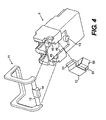
- FIG. 4 shows an embodiment of a bail latch mechanism in exploded form.
- FIG. 1 ( a ) illustrates an embodiment of the present invention.
- FIG. 1 ( a ) shows a bottom view of an optical module 1 with a bail latch mechanism 10 according to the present invention.
- Optical module 1 includes receptacles 2 at one end to accept optical communication connectors.
- a connector 3 is shown inserted into one of receptacles 2 .
- optical module 1 is inserted into a host system (not shown), which may be a data processing system such as a network server, a mainframe computer or any other electronic system that accepts data in the form of electrical signals.
- Connector 3 includes an optical fiber coupling the host system to other systems optically. For example, various components of a computer network may be connected by means of optical fibers between optical modules 1 .
- Optical module 1 may include internal circuitry to convert optical signals to electrical signals and electrical signals to optical signals. Typically, conversions involve converting between serial optical signals and parallel electrical signals. This circuitry is usually formed on a printed circuit board (PCB).
- PCB printed circuit board
- the housing 4 of optical module 1 covers the circuitry to protect it and to provide structural integrity. Housing 4 may be a single piece or may be several pieces making a single rigid assembly. For example, a separate housing portion 5 may be used for the optical connections at the front of optical module 1 . Housing portion 5 is connected to the housing 4 to form a rigid assembly.
- Bail latch mechanism 10 of FIG. 1 ( a ) is used to physically secure optical module 1 within a host system. Securing optical module 1 allows the electrical connection to the host to be protected from being accidentally disconnected or disturbed. Because adjacent modules are close together there is a risk of disturbing neighboring modules when one module is being removed from the host. Also, if optical module 1 is not secured it may be disconnected from the host when the optical fiber is removed. Bail latch mechanism 10 provides a latched state in which optical module 1 is physically secured to the host, and a de-latched state in which optical module 1 may be withdrawn from the host. Normally, optical module 1 is inserted into a port in the host system. The host SFP cage assembly (host cage) forms the walls of the port.
- host cage assembly host cage
- Optical module 1 is constrained vertically and laterally by the cage so that it can only move in one direction, in or out of the port. When latched, optical module 1 is captured in this direction also. When de-latched optical module 1 may be withdrawn from the cage.
- Bail latch mechanism 10 includes a bail 11 , a latch key 12 and a latch boss 13 .
- Bail 11 has a shaft 15 that is mounted to the body of optical module 1 so that it can rotate.
- Shaft 15 may be mounted to the lower surface of optical module 1 as shown in FIG. 1 ( a ).
- the length of shaft 15 is approximately the same as the width of optical module 1 .
- U-shaped arms extend from it, perpendicular to its axis. These arms are designed so that the U-shaped portions may fit around the front of optical module 1 .
- the arms are connected by a bar at the other end (not visible in FIG. 1 ( a )).
- Shaft 15 has a cam surface 14 .
- Cam surface 14 is contoured so that as shaft 15 rotates cam surface 14 pushes against latch key 12 .
- cam surface 14 converts the rotational movement of bail 11 into a force that acts to displace latch key 12 .
- Bail 11 is located at the front of optical module 1 where it serves a dual purpose. The position of bail 11 determines the state of the mechanism, latched or de-latched, as described further below. Also, bail 11 may be used to remove optical module 1 since it provides an attachment to optical module 1 that can easily be gripped and by which optical module 1 can be pulled out of the host cage. When bail 11 is moved to the de-latched position, part of it extends clear of the front of optical module 1 where it is easily gripped without disturbing neighboring modules. Bail 11 must be capable of withstanding the force needed to de-latch the mechanism and to withdraw optical module 1 . Bail 11 must also be sufficiently rigid so that it does not deform.
- Bail 11 may be made of plastic.
- a Nylon resin with 25% glass fiber may be used.
- One such plastic is Zytel® made by E.I. du Pont de Nemours and Company. Bails made out of metal are generally round when looked at in cross-section because they are formed from wire.
- Plastic bails are not limited in this way. Plastic bails may have a variety of shapes chosen to improve their mechanical properties. For example, bail 11 may be rectangular in cross-section. Also, the color of the plastic of bail 11 may be chosen to allow color-coding. Another alternative is to modify the material to make the plastic look like metal. The mechanical characteristics of plastics are well suited to this application.
- the stress generated in bail 11 when removing a typical module of this kind from a host system is well below the failure tensile stress of a plastic such as Zytel®. Even with an unbalanced force (i.e. the extraction force not in the direction of extraction of optical module 1 ) the stress generated is below the failure tensile stress.
- Another advantage of plastic for this purpose is that it is somewhat elastic. This allows bail 11 to be snapped into place. With careful control of the tolerances of bail 11 and opening that contains it, the bail may be forced into place without damage. The result is a simple assembly procedure.
- Latch key 12 is designed to fit within a recess 16 in the body in such a way that it may slide in one direction, but is constrained from moving in any other direction.
- FIG. 1 ( a ) shows latch key 12 on the bottom of optical module 1 , but it could also be mounted on the top or side of optical module 1 if the host was configured to accept that configuration and the positions of the other parts of bail latch mechanism 10 were changed accordingly.
- Cam surface 14 of bail 11 applies a force to one end of latch key 12 .
- the other end of latch key 12 has a wedge shaped portion 17 .
- Wedge shaped portion 17 forms an acute angle at the bottom of recess 16 and has an angled surface extending from the bottom.
- Latch boss 13 forms a protrusion from optical module 1 and remains stationary with respect to it.
- Latch boss 13 may be formed integral with the housing portion 5 or otherwise mounted so that its position is fixed to module 1 . Having the position of latch boss 13 formed integrally with housing portion 5 reduces the number of moving parts. Moving parts are prone to stress failure and may suffer wear and fatigue over time. Therefore, reducing the number of moving parts is advantageous. Also, because latch boss 13 does not move, there is no need for a spring to bias latch boss 13 . This eliminates another source of failure from the mechanism.
- optical modules 1 may be arranged together within a host system 24 as shown in FIG. 1 ( b ).
- optical modules 1 are spaced closely together to allow a large number of receptacles 2 in a given space. This allows a large number of optical connectors 3 to be connected to the host system 24 .
- the present embodiment allows closer spacing than many similar optical modules because access to the sides of optical modules 1 is not required to insert or remove optical module 1 from the host. This is because the bail 11 can be accessed from the front of optical module 1 and used to de-latch optical module 1 from host system 24 .
- FIGS. 2 ( a )- 2 ( c ) show bail latch mechanism 10 as it is moved from the latched to the de-latched state.
- optical module 1 is captured within host cage 23 .
- the latch 20 engages latch boss 13 and holds optical module 1 from being withdrawn from the host.
- Latch 20 (also called a retention tab or tap bend) is attached to host cage 23 to engage optical module 1 and to capture it within host cage 23 .
- the latch 20 along with other aspects of host cage 23 , is governed by the MSA.
- Latch 20 may be made of a spring material such as Phosphor Bronze.
- Latch 20 has an opening 21 to engage the latch boss. The dimensions of this opening are also determined by the MSA.
- FIG. 2 ( a ) shows latch 20 in a position where latch boss 13 is in opening 21 of the latch 20 , and a retaining portion 22 of latch 20 blocks the latch boss, and therefore optical module 1 , from moving out of the host.
- Bail 11 is designed to fit closely to the front of optical module 1 and provide a low profile.
- a protrusion 33 may be provided at the opposite side of bail 11 from shaft 15 .
- Protrusion 33 corresponds to a recess 34 provided in housing portion 5 to hold protrusion 33 .
- Protrusion 33 and recess 34 hold bail 11 in place and provide a locking mechanism when in the latched position.
- the latched state is the normal state of optical module 1 when it is in use. In this position, optical module 1 is electrically connected to the host system. Optical receptacles 2 at the front of optical module 1 are accessible in this state so that optical connectors 3 may be inserted or removed. Insertion and removal of connectors 3 is possible without disturbing the connection between optical module 1 and the host because optical module 1 is securely held within cage 23 .
- FIG. 2 ( b ) shows bail latch mechanism 10 as it is moved from the latched state to the de-latched state.
- a user pulls bail 11 so that it rotates and extends outward from optical module 1 .
- Bail 11 has a shaft portion 15 that forms the axis of rotation of the bail and a lever portion 30 that extends outward from shaft 15 and provides a grip for the user.
- the lever portion has an arm 31 attached to either end of shaft 15 and a bar 32 connects the arms at their other end.
- Shaft portion 15 has a cam surface 14 as shown. Cam surface 14 is contoured so that it produces a force against latch key 12 as bail 11 rotates. This force causes latch key 12 to move towards latch boss 13 .
- latch key 12 moves away from the front of optical module 1 as bail 11 is rotated. This motion of latch key 12 causes the latch key to exert a force against retaining portion 22 of latch 20 .
- latch 20 extends into a recess 40 between latch boss 13 and the latch key 12 .
- latch key 12 occupies an increasing portion of recess 40 .
- the surface 50 of latch key 12 as it impinges on space 40 is angled to push latch 20 outward from the body of optical module 1 .
- latch 20 is displaced from recess 40 . This displacement of latch 20 eventually causes it to cease to engage the latch boss.
- latch key 12 While latch key 12 slides in a direction that is from the front to the back of optical module 1 , latch 20 must be pushed in a direction normal to the movement of latch key 12 .
- Latch key 12 acts as a wedge between housing portion 5 and latch 20 so that as latch key 12 moves further towards latch boss 13 , surface 50 pushes latch 20 outward from optical module 1 .
- FIG. 2 ( c ) shows bail latch mechanism 10 in the de-latched state.
- Bail 11 is rotated so that it extends outward from the front of optical module 1 .
- This provides a grip for extraction of optical module 1 from host cage 23 .
- latch key 12 has moved sufficiently to displace latch 20 from recess 40 behind latch boss 13 and thus cause latch 20 to disengage.
- Latch 20 is no longer holding latch boss 13 and therefore optical module 1 is free to be removed from the host.
- Optical module 1 may be removed by simply continuing to exert an outward force on bail 11 in the direction indicated by the arrow in FIG. 2 ( c ). Therefore, the optical module 1 may be removed from the host cage 23 by a single pull and rotate motion of the bail 11 .
- FIG. 3 ( a ) illustrates a bottom view of an embodiment of the present invention where an optical module 1 is latched within a cage 23 and optical connectors 3 are inserted in receptacles 2 .
- FIG. 3 ( a ) shows the latch 20 engaging the latch boss 13 .
- FIG. 3 ( b ) illustrates in cross section, optical module 1 in the latched position. Retaining portion 22 of latch 20 blocks the latch boss 13 from moving. In this state, protrusion 33 is held within recess 34 . Thus, the bail is held in the latched position.
- FIG. 4 illustrates an example of bail latch mechanism 10 in exploded form.
- This perspective shows housing portion 5 , bail 11 and latch key 12 .
- Bail 11 attaches to housing portion 5 by pressing the shaft portion 15 into the corresponding openings 45 in the housing portion 5 .
- the size of openings 45 is selected to allow the shaft 15 to be captured once it is inserted so that it remains attached. Openings 45 allow shaft 15 to rotate freely.
- FIG. 3 also shows the retaining portions 51 of latch key 12 . Retaining portions 51 extend from latch key 12 to allow latch key 12 to be captured by housing portion 5 .
- Housing portion 5 has retaining portions 46 that extend over retaining portions 51 and thus capture latch key 12 against housing portion 5 .
Landscapes
- Physics & Mathematics (AREA)
- General Physics & Mathematics (AREA)
- Optics & Photonics (AREA)
- Engineering & Computer Science (AREA)
- Microelectronics & Electronic Packaging (AREA)
- Optical Couplings Of Light Guides (AREA)
Abstract
Description
Claims (16)
Priority Applications (1)
| Application Number | Priority Date | Filing Date | Title |
|---|---|---|---|
| US10/364,685 US6929403B1 (en) | 2003-02-10 | 2003-02-10 | Small form-factor pluggable bail latch |
Applications Claiming Priority (1)
| Application Number | Priority Date | Filing Date | Title |
|---|---|---|---|
| US10/364,685 US6929403B1 (en) | 2003-02-10 | 2003-02-10 | Small form-factor pluggable bail latch |
Publications (1)
| Publication Number | Publication Date |
|---|---|
| US6929403B1 true US6929403B1 (en) | 2005-08-16 |
Family
ID=34825794
Family Applications (1)
| Application Number | Title | Priority Date | Filing Date |
|---|---|---|---|
| US10/364,685 Expired - Lifetime US6929403B1 (en) | 2003-02-10 | 2003-02-10 | Small form-factor pluggable bail latch |
Country Status (1)
| Country | Link |
|---|---|
| US (1) | US6929403B1 (en) |
Cited By (22)
| Publication number | Priority date | Publication date | Assignee | Title |
|---|---|---|---|---|
| US20040228582A1 (en) * | 2003-05-16 | 2004-11-18 | Nec Corporation | Optical module capable of facilitating release from locking state with cage which accommodates optical module |
| US20050117855A1 (en) * | 2003-11-27 | 2005-06-02 | Optoelectronics Solutions Co., Ltd. | Latch type optical module |
| US20050191013A1 (en) * | 2004-03-01 | 2005-09-01 | Fujitsu Limited | Data link module |
| US20060121769A1 (en) * | 2004-12-06 | 2006-06-08 | Jds Uniphase Corporation, State Of Incorporation: Delaware | Transceiver delatching mechanism |
| US20060215968A1 (en) * | 2004-02-20 | 2006-09-28 | Andrew Kayner | Transceiver module |
| US20080134350A1 (en) * | 2006-07-31 | 2008-06-05 | 55 Consultants, Inc. | Computer chassis for improved security and connectivity of secured items |
| US20080132101A1 (en) * | 2006-11-30 | 2008-06-05 | International Business Machines Corporation | Apparatus for Releasing Latching Connectors |
| US20080314099A1 (en) * | 2007-06-20 | 2008-12-25 | Hitachi Cable, Ltd. | Optical transceiver |
| US20090176401A1 (en) * | 2008-01-07 | 2009-07-09 | Applied Optoelectronics, Inc. | Pluggable form factor release mechanism |
| US20090321301A1 (en) * | 2006-08-30 | 2009-12-31 | Wuhan Telecommunication Devices Co., Ltd. | Bail Type Unlocking and Resetting Device for Hot Pluggable Opto-electronic Module |
| US20100067199A1 (en) * | 2008-09-12 | 2010-03-18 | Hong Fu Jin Precision Industry(Shenzhen) Co., Ltd. | Optoelectronic transceiver assembly and release mechanism employed therein |
| US20100098385A1 (en) * | 2008-10-21 | 2010-04-22 | Nec Corporation | Optical module locking mechanism and method of locking and releasing a locking state of an optical module |
| US20120063100A1 (en) * | 2010-09-15 | 2012-03-15 | Hon Hai Precision Industry Co., Ltd. | Electronic module with improved latch mechanism |
| CN101330327B (en) * | 2007-06-20 | 2012-09-19 | 日立电线株式会社 | Optical transceiver |
| US20130178090A1 (en) * | 2009-10-05 | 2013-07-11 | Finisar Corporation | Latching mechanism for a module |
| US9001515B2 (en) | 2012-04-20 | 2015-04-07 | Cisco Technology, Inc. | Universal pull tab release for modules including fiber optic and cable accessibilities |
| US9263831B2 (en) | 2013-12-11 | 2016-02-16 | Foxconn Interconnect Technology Limited | Plug having improved release mechanism |
| EP2895901A4 (en) * | 2012-09-15 | 2016-08-24 | Finisar Corp | Latch mechanism for communications module |
| US20170324194A1 (en) * | 2014-10-31 | 2017-11-09 | Wuhan Telecommunication Devices Co., Ltd. | Module retracting type installing and uninstalling device |
| US20180062312A1 (en) * | 2016-08-30 | 2018-03-01 | Tyco Electronics Japan G.K. | Lever Type Connector |
| CN109100834A (en) * | 2017-06-20 | 2018-12-28 | 光红建圣股份有限公司 | frame mechanism |
| US10193251B2 (en) | 2014-07-31 | 2019-01-29 | Hewlett Packard Enterprise Development Lp | Next generation form factor (NGFF) carrier |
Citations (6)
| Publication number | Priority date | Publication date | Assignee | Title |
|---|---|---|---|---|
| US4260210A (en) * | 1979-06-29 | 1981-04-07 | International Business Machines Corporation | Pluggable module actuation and retention device |
| US5019769A (en) * | 1990-09-14 | 1991-05-28 | Finisar Corporation | Semiconductor laser diode controller and laser diode biasing control method |
| US5901263A (en) * | 1997-09-12 | 1999-05-04 | International Business Machines Corporation | Hot pluggable module integrated lock/extraction tool |
| US6439918B1 (en) * | 2001-10-04 | 2002-08-27 | Finisar Corporation | Electronic module having an integrated latching mechanism |
| US6494623B1 (en) * | 2001-08-09 | 2002-12-17 | Infineon Technologies Ag | Release mechanism for pluggable fiber optic transceiver |
| US6553603B1 (en) * | 1998-02-17 | 2003-04-29 | William A. Jolly | Athletic shoe cleaner |
-
2003
- 2003-02-10 US US10/364,685 patent/US6929403B1/en not_active Expired - Lifetime
Patent Citations (6)
| Publication number | Priority date | Publication date | Assignee | Title |
|---|---|---|---|---|
| US4260210A (en) * | 1979-06-29 | 1981-04-07 | International Business Machines Corporation | Pluggable module actuation and retention device |
| US5019769A (en) * | 1990-09-14 | 1991-05-28 | Finisar Corporation | Semiconductor laser diode controller and laser diode biasing control method |
| US5901263A (en) * | 1997-09-12 | 1999-05-04 | International Business Machines Corporation | Hot pluggable module integrated lock/extraction tool |
| US6553603B1 (en) * | 1998-02-17 | 2003-04-29 | William A. Jolly | Athletic shoe cleaner |
| US6494623B1 (en) * | 2001-08-09 | 2002-12-17 | Infineon Technologies Ag | Release mechanism for pluggable fiber optic transceiver |
| US6439918B1 (en) * | 2001-10-04 | 2002-08-27 | Finisar Corporation | Electronic module having an integrated latching mechanism |
Cited By (36)
| Publication number | Priority date | Publication date | Assignee | Title |
|---|---|---|---|---|
| US20040228582A1 (en) * | 2003-05-16 | 2004-11-18 | Nec Corporation | Optical module capable of facilitating release from locking state with cage which accommodates optical module |
| US7325975B2 (en) * | 2003-05-16 | 2008-02-05 | Nec Corporation | Optical module with lever that abuts case to release latch from locking state with cage which accommodates optical module |
| US20050117855A1 (en) * | 2003-11-27 | 2005-06-02 | Optoelectronics Solutions Co., Ltd. | Latch type optical module |
| US7189013B2 (en) * | 2003-11-27 | 2007-03-13 | Optoelectronics Solutions Co., Ltd. | Latch type optical module |
| US20060215968A1 (en) * | 2004-02-20 | 2006-09-28 | Andrew Kayner | Transceiver module |
| US7303336B2 (en) * | 2004-02-20 | 2007-12-04 | Jds Uniphase Corporation | Transceiver module |
| US20050191013A1 (en) * | 2004-03-01 | 2005-09-01 | Fujitsu Limited | Data link module |
| US7261475B2 (en) * | 2004-03-01 | 2007-08-28 | Fujitsu Limited | Data link module |
| US20060121769A1 (en) * | 2004-12-06 | 2006-06-08 | Jds Uniphase Corporation, State Of Incorporation: Delaware | Transceiver delatching mechanism |
| US7090527B2 (en) * | 2004-12-06 | 2006-08-15 | Jds Uniphase Corporation | Transceiver delatching mechanism |
| US20080134350A1 (en) * | 2006-07-31 | 2008-06-05 | 55 Consultants, Inc. | Computer chassis for improved security and connectivity of secured items |
| US20090321301A1 (en) * | 2006-08-30 | 2009-12-31 | Wuhan Telecommunication Devices Co., Ltd. | Bail Type Unlocking and Resetting Device for Hot Pluggable Opto-electronic Module |
| US7712969B2 (en) * | 2006-08-30 | 2010-05-11 | Wuhan Telecommunication Devices Co., Ltd. | Bail type unlocking and resetting device for hot pluggable opto-electronic module |
| US20080132101A1 (en) * | 2006-11-30 | 2008-06-05 | International Business Machines Corporation | Apparatus for Releasing Latching Connectors |
| US7517241B2 (en) * | 2006-11-30 | 2009-04-14 | International Business Machines Corporation | Apparatus for releasing latching connectors |
| US20080314099A1 (en) * | 2007-06-20 | 2008-12-25 | Hitachi Cable, Ltd. | Optical transceiver |
| US7665904B2 (en) * | 2007-06-20 | 2010-02-23 | Hitachi Cable, Ltd. | Optical transceiver |
| CN101330327B (en) * | 2007-06-20 | 2012-09-19 | 日立电线株式会社 | Optical transceiver |
| US20090176401A1 (en) * | 2008-01-07 | 2009-07-09 | Applied Optoelectronics, Inc. | Pluggable form factor release mechanism |
| US7766686B2 (en) * | 2008-01-07 | 2010-08-03 | Applied Optoelectronics, Inc. | Pluggable form factor release mechanism |
| US20100067199A1 (en) * | 2008-09-12 | 2010-03-18 | Hong Fu Jin Precision Industry(Shenzhen) Co., Ltd. | Optoelectronic transceiver assembly and release mechanism employed therein |
| US8023270B2 (en) | 2008-09-12 | 2011-09-20 | Hong Fu Jin Precision Industry (Shenzhen) Co., Ltd. | Optoelectronic transceiver assembly and release mechanism employed therein |
| US20100098385A1 (en) * | 2008-10-21 | 2010-04-22 | Nec Corporation | Optical module locking mechanism and method of locking and releasing a locking state of an optical module |
| US20130178090A1 (en) * | 2009-10-05 | 2013-07-11 | Finisar Corporation | Latching mechanism for a module |
| US8934752B2 (en) * | 2009-10-05 | 2015-01-13 | Finisar Corporation | Latching mechanism for a module |
| US20120063100A1 (en) * | 2010-09-15 | 2012-03-15 | Hon Hai Precision Industry Co., Ltd. | Electronic module with improved latch mechanism |
| US8537558B2 (en) * | 2010-09-15 | 2013-09-17 | Hon Hai Precision Industry Co., Ltd. | Electronic module with improved latch mechanism |
| US9001515B2 (en) | 2012-04-20 | 2015-04-07 | Cisco Technology, Inc. | Universal pull tab release for modules including fiber optic and cable accessibilities |
| EP2895901A4 (en) * | 2012-09-15 | 2016-08-24 | Finisar Corp | Latch mechanism for communications module |
| US9263831B2 (en) | 2013-12-11 | 2016-02-16 | Foxconn Interconnect Technology Limited | Plug having improved release mechanism |
| US10193251B2 (en) | 2014-07-31 | 2019-01-29 | Hewlett Packard Enterprise Development Lp | Next generation form factor (NGFF) carrier |
| US20170324194A1 (en) * | 2014-10-31 | 2017-11-09 | Wuhan Telecommunication Devices Co., Ltd. | Module retracting type installing and uninstalling device |
| US9954316B2 (en) * | 2014-10-31 | 2018-04-24 | Wuhan Telecommunication Devices Co., Ltd. | Module retracting type installing and uninstalling device |
| US20180062312A1 (en) * | 2016-08-30 | 2018-03-01 | Tyco Electronics Japan G.K. | Lever Type Connector |
| US10511125B2 (en) * | 2016-08-30 | 2019-12-17 | Tyco Electronics Japan G.K. | Connector having a lever |
| CN109100834A (en) * | 2017-06-20 | 2018-12-28 | 光红建圣股份有限公司 | frame mechanism |
Similar Documents
| Publication | Publication Date | Title |
|---|---|---|
| US6929403B1 (en) | Small form-factor pluggable bail latch | |
| US6439918B1 (en) | Electronic module having an integrated latching mechanism | |
| US7507111B2 (en) | Electronic modules having integrated lever-activated latching mechanisms | |
| US7066746B1 (en) | Electronic module having an integrated latching mechanism | |
| US8272790B2 (en) | Outdoor transceiver connector | |
| US7314384B2 (en) | Electronic modules having an integrated connector detachment mechanism | |
| KR100319033B1 (en) | Connector assembly | |
| US9261653B2 (en) | Fiber optic plug assembly and optical connector system | |
| JP4093862B2 (en) | Optical fiber module latch release mechanism | |
| US7090523B2 (en) | Release mechanism for transceiver module assembly | |
| JP7160959B2 (en) | Adjustable polarity fiber optic connector assembly with shortened rotatable boot assembly | |
| US6851867B2 (en) | Cam-follower release mechanism for fiber optic modules with side delatching mechanisms | |
| US7066765B2 (en) | Shielding tabs for reduction of electromagnetic interference | |
| KR20210031788A (en) | Narrow width adapters and connectors with modular latching arm | |
| US6991481B1 (en) | Method and apparatus for a latchable and pluggable electronic and optical module | |
| US6926551B1 (en) | Pluggable transceiver latching mechanism | |
| US10156689B2 (en) | Latch for communication module | |
| US20140153195A1 (en) | Communication module | |
| US8764312B2 (en) | Optical connector plug having improved latching mechanism | |
| NL1024850C2 (en) | Cable connector system in telecom application, has spring to exert biasing force on locking arm after rotating lock arm to unlocked position, so that locking arm is not rotated backwards to locked position | |
| EP2345115B1 (en) | Transceiver module for communications network | |
| US8613630B2 (en) | Latch assembly for a pluggable electronic module | |
| EP4228105A1 (en) | Coding clip, plug assembly and connector assembly |
Legal Events
| Date | Code | Title | Description |
|---|---|---|---|
| AS | Assignment |
Owner name: PINE PHOTONICS COMMUNICATIONS, INC., CALIFORNIA Free format text: ASSIGNMENT OF ASSIGNORS INTEREST;ASSIGNORS:ARCINIEGAS, GERMAN;ZHANG, LIN;REEL/FRAME:013956/0624 Effective date: 20030206 |
|
| AS | Assignment |
Owner name: OPNEXT, INC., CALIFORNIA Free format text: ASSIGNMENT OF ASSIGNORS INTEREST;ASSIGNOR:PINE PHOTONICS COMMUNICATIONS, INC.;REEL/FRAME:014950/0691 Effective date: 20040128 |
|
| STCF | Information on status: patent grant |
Free format text: PATENTED CASE |
|
| CC | Certificate of correction | ||
| FPAY | Fee payment |
Year of fee payment: 4 |
|
| FPAY | Fee payment |
Year of fee payment: 8 |
|
| FPAY | Fee payment |
Year of fee payment: 12 |
|
| AS | Assignment |
Owner name: OCLARO FIBER OPTICS, INC., CALIFORNIA Free format text: CHANGE OF NAME;ASSIGNOR:OPNEXT, INC.;REEL/FRAME:046416/0022 Effective date: 20151216 |
|
| AS | Assignment |
Owner name: DEUTSCHE BANK AG NEW YORK BRANCH, AS COLLATERAL AGENT, NEW YORK Free format text: PATENT SECURITY AGREEMENT;ASSIGNORS:LUMENTUM OPERATIONS LLC;OCLARO FIBER OPTICS, INC.;OCLARO, INC.;REEL/FRAME:047788/0511 Effective date: 20181210 Owner name: DEUTSCHE BANK AG NEW YORK BRANCH, AS COLLATERAL AG Free format text: PATENT SECURITY AGREEMENT;ASSIGNORS:LUMENTUM OPERATIONS LLC;OCLARO FIBER OPTICS, INC.;OCLARO, INC.;REEL/FRAME:047788/0511 Effective date: 20181210 |
|
| AS | Assignment |
Owner name: LUMENTUM FIBER OPTICS INC., CALIFORNIA Free format text: CHANGE OF NAME;ASSIGNOR:OCLARO FIBER OPTICS, INC.;REEL/FRAME:049843/0453 Effective date: 20190603 |
|
| AS | Assignment |
Owner name: OCLARO, INC., CALIFORNIA Free format text: RELEASE BY SECURED PARTY;ASSIGNOR:DEUTSCHE AG NEW YORK BRANCH;REEL/FRAME:051287/0556 Effective date: 20191212 Owner name: LUMENTUM OPERATIONS LLC, CALIFORNIA Free format text: RELEASE BY SECURED PARTY;ASSIGNOR:DEUTSCHE AG NEW YORK BRANCH;REEL/FRAME:051287/0556 Effective date: 20191212 Owner name: OCLARO FIBER OPTICS, INC., CALIFORNIA Free format text: RELEASE BY SECURED PARTY;ASSIGNOR:DEUTSCHE AG NEW YORK BRANCH;REEL/FRAME:051287/0556 Effective date: 20191212 |