US6891890B1 - Multi-phase motion estimation system and method - Google Patents
Multi-phase motion estimation system and method Download PDFInfo
- Publication number
- US6891890B1 US6891890B1 US09/842,199 US84219901A US6891890B1 US 6891890 B1 US6891890 B1 US 6891890B1 US 84219901 A US84219901 A US 84219901A US 6891890 B1 US6891890 B1 US 6891890B1
- Authority
- US
- United States
- Prior art keywords
- pixel
- difference measure
- accurate
- pixel block
- pixels
- Prior art date
- Legal status (The legal status is an assumption and is not a legal conclusion. Google has not performed a legal analysis and makes no representation as to the accuracy of the status listed.)
- Expired - Fee Related, expires
Links
Images


Classifications
-
- H—ELECTRICITY
- H04—ELECTRIC COMMUNICATION TECHNIQUE
- H04N—PICTORIAL COMMUNICATION, e.g. TELEVISION
- H04N19/00—Methods or arrangements for coding, decoding, compressing or decompressing digital video signals
- H04N19/50—Methods or arrangements for coding, decoding, compressing or decompressing digital video signals using predictive coding
- H04N19/503—Methods or arrangements for coding, decoding, compressing or decompressing digital video signals using predictive coding involving temporal prediction
- H04N19/51—Motion estimation or motion compensation
- H04N19/533—Motion estimation using multistep search, e.g. 2D-log search or one-at-a-time search [OTS]
-
- H—ELECTRICITY
- H04—ELECTRIC COMMUNICATION TECHNIQUE
- H04N—PICTORIAL COMMUNICATION, e.g. TELEVISION
- H04N19/00—Methods or arrangements for coding, decoding, compressing or decompressing digital video signals
- H04N19/42—Methods or arrangements for coding, decoding, compressing or decompressing digital video signals characterised by implementation details or hardware specially adapted for video compression or decompression, e.g. dedicated software implementation
- H04N19/43—Hardware specially adapted for motion estimation or compensation
Definitions
- the present invention relates to digital video encoding, such as MPEG and AVI. More specifically, the present invention relates to methods of motion estimation for encoding digital images of a digital video stream.
- ICs integrated circuits
- processing and memory capabilities With increasing processing and memory capabilities, many formerly analog tasks are being performed digitally. For example, images, audio and even full motion video can now be produced, distributed, and used in digital formats.
- FIG. 1 ( a ) is an illustrative diagram of a digital video stream 100 .
- Digital video stream 100 comprises a series of individual digital images 100 _ 0 to 100 _N, each digital image of a video stream is often called a frame. For full motion video a video frame rate of 60 images per second is desired.
- a digital image 100 _Z comprises a plurality of picture elements (pixels). Specifically, digital image 100 _Z comprises Y rows of X pixels. For clarity, pixels in a digital image are identified using a 2-dimensional coordinate system. As shown in FIG. 1 ( b ), pixel P(0,0) is in the top left corner of digital image 100 _Z.
- Pixel P(X ⁇ 1,0) is in the top right corner of digital image 100 _Z.
- Pixel P(0,Y ⁇ 1) is in the bottom left corner and pixel P(X ⁇ 1, Y ⁇ 1) is in the bottom right corner.
- Typical image sizes for digital video streams include 720 ⁇ 480, 640 ⁇ 480, 320 ⁇ 240 and 160 ⁇ 120.
- FIG. 2 shows a typical digital video system 200 , which includes a video capture device 210 , a video encoder 220 , a video channel 225 , a video decoder 230 , a video display 240 , and an optional video storage system 250 .
- Video capture device 210 typically a video camera, provides a video stream to video encoder 220 .
- Video encoder 220 digitizes and encodes the video stream and sends the encoded digital video stream over channel 225 to video decoder 230 .
- Video decoder 230 decodes the encoded video stream from channel 225 and displays the video images on video display 240 .
- Channel 225 could be for example, a local area network, the internet, telephone lines with modems, or any other communication connections.
- Video decoder 230 could also receive a video data stream from video storage system 250 .
- Video storage system 250 can be for example, a video compact disk system, a hard disk storing video data, or a digital video disk system.
- channel 225 is typically limited in bandwidth.
- a full-motion digital video stream can comprise 60 images a second. Using an image size of 640 ⁇ 480, a full motion video stream would have 18.4 million pixels per second. In a full color video stream each pixel comprises three bytes of color data. Thus, a full motion video stream would require a transfer rate in excess of 52 megabytes a second over channel 225 .
- most users can only support a bandwidth of approximately 56 Kilobits per second.
- digital video streams must be compressed.
- a digital video stream includes digital image 301 and 302 .
- Digital image 301 includes a video object 310 _ 1 and video object 340 _ 1 on a blank background.
- Digital image 302 includes a video object 310 _ 2 , which is the same as video object 310 _ 1 , and a video object 340 _ 2 , which is the same as video object 340 _ 1 .
- a digital video stream could be encoded to simply send the information that video object 310 _ 1 from digital image 301 has moved three pixels to the left and two pixels down and that video object 340 _ 1 from digital image 301 has moved one pixel down and four pixels to the left.
- video encoder 220 can send digital image 301 and the movement information, usually encoded as a two dimensional motion vector, regarding the objects in digital image 301 to video decoder 230 .
- Video decoder 230 can then generate digital image 302 using digital image 301 and the motion vectors supplied by video encoder 220 .
- additional digital images in the digital video stream containing digital images 301 and 302 can be generated from additional motion vectors.
- FIG. 4 illustrates a digital image 410 that is divided into a plurality of square macroblocks.
- macroblocks are identified using a 2-dimensional coordinate system. As shown in FIG. 4 , macroblock MB(0,0) is in the top left corner of digital image 410 . Macroblock MB(X ⁇ 1,0) is in the top right corner of digital image 410 . Macroblock MB(0,Y ⁇ 1) is in the bottom left corner and macroblock MB(X ⁇ 1, Y ⁇ 1) is in the bottom right corner. As illustrated in FIG. 5 ( a ), a typical size for a macroblock 510 is eight pixels by eight pixels. As illustrated in FIG. 5 ( b ), another typical size for a macroblock is 16 pixels by 16 pixels. For convenience, macroblocks and digital images are illustrated with bold lines after every four pixels in both the vertical and horizontal direction. These bold lines are for the convenience only and have no bearing on actual implementation of embodiments of the present invention.
- each macroblock MB(x, y) of a digital image is compared with the preceding digital image to determine which area of the preceding image best matches macroblock MB(x, y).
- the area of the preceding image best matching a macroblock is called an origin block OB.
- an origin block has the same size and shape as the macroblock.
- a difference measure is used to measure the amount of difference between the macroblock and each possible origin block.
- a value such as the luminance of each pixel in the macroblock is compared to the luminance of a corresponding pixel in the origin block.
- the sum of absolute differences (SAD) of all the values (such as luminance) is the difference measure.
- Other embodiments of the present invention may use other difference measures.
- one embodiment of the present invention uses the sum of square differences as the difference measures. For clarity, only SAD is described in detail, those skilled in the art can easily adapt other difference measures for use with different embodiments of the present invention. The lower the difference measure the better the match between the origin block and the macroblock.
- the motion vector for macroblock MB(x, y) is simply the two-dimensional vector which defines the difference in location of a reference pixel on the origin block with a corresponding reference pixel on the macroblock.
- the reference pixel in the examples contained herein uses the top left pixel of the macroblock and the origin block as the reference pixel.
- the reference pixel of macroblock MB(0,0) of FIG. 4 is pixel(0,0).
- the reference pixel of macroblock MB(X ⁇ 1, Y ⁇ 1) assuming an 8 ⁇ 8 reference block is pixel P(8*(X ⁇ 1), 8*(Y ⁇ 1)).
- FIGS. 6 ( a )- 6 ( f ) illustrate a conventional matching method to find the object block in preceding image 601 for macroblock 610 .
- the method in FIGS. 6 ( a )- 6 ( f ) is to compare each macroblock of a digital image with each pixel block, i.e., a block of pixels of the same size and same shape as the macroblock in the preceding image, to determine the difference measure for each pixel block.
- the pixel block with the lowest difference measure is determined to be the origin block of the macroblock. As illustrated in FIG.
- a group of pixels 610 with reference pixel RP(0,0), in preceding image 601 is compared to an 8 ⁇ 8 macroblock MB(x, y) to determine a difference measure for the group of pixels 610 .
- the group of pixels 620 with reference pixel RP(1,0) is compared to macroblock MB(x, y) to determine a difference measure for pixel block 620 .
- pixel block 640 As illustrated in FIG. 6 ( d ), after pixel block 630 , pixel block 640 , with reference pixel (0,1), is compared with macroblock MB(x, y) to determine a difference measure for pixel block 640 . Each pixel block to the right of group of pixel 650 is then in turn compared to macroblock MB(x, y) to determine difference measures for each pixel block. Eventually, as illustrated in FIG. 6 ( e ), the group of pixels 660 having reference pixel RP(19,1) is compared with macroblock MB(x, y) to determine difference measures for pixel block 660 . This process continues until finally as illustrated in FIG.
- pixel block 690 with reference pixel (19,11) is compared with macroblock MB(x, y) to determine a difference measure for pixel block 690 .
- the process continues until a pixel block having only one pixel within preceding image 601 , e.g., a pixel block having reference pixel (22, 15) is compared with macroblock MB(x, y).
- some embodiments may start with pixel blocks having reference pixels with negative coordinates. For example, rather than starting with pixel block 610 having reference pixels RP(0, 0), some methods would start with a pixel block having reference pixel RP( ⁇ 7, ⁇ 7).
- Conventional padding techniques can be used to fill the pixel block which require pixels that are outside of preceding image 601 .
- a common padding technique is to use a copy of the closest pixel from preceding image 601 for each pixel outside of preceding image 601 .
- FIGS. 6 ( a )- 6 ( f ) would require a very large number of calculations to encode a digital image.
- a 640 ⁇ 480 image comprises 1200 16 ⁇ 16 macroblocks of 256 pixels each.
- To encode a digital image from a preceding digital image would require comparing each of the 1200 16 ⁇ 16 macroblocks with each of the 298,304 pixel blocks (16 ⁇ 16 blocks) in the preceding image.
- Each comparison would require calculating 256 absolute differences.
- encoding of a digital image requires calculating approximately 91.6 billion absolute differences. For many applications this large number of calculations is unacceptable.
- real time digital video data may need to be encoded for live broadcasts over a computer network, such as the internet.
- FIGS. 6 ( a )- 6 ( f ) Since a digital video sequence ideally has 60 frames per second, the method of FIGS. 6 ( a )- 6 ( f ) would require calculating approximately 5.4 trillion absolute differences per second. The computing power required to perform the calculations would be cost prohibitive for most applications. Hence there is a need for a method or structure to perform motion estimation for encoding digital video streams using motion vectors of macroblocks.
- the present invention provides a method and system for computing motion vectors of macroblocks of a digital image using a preceding image that reduces the computational burden of determining the motion vectors.
- a video encoder calculates the motion vector of a macroblock using a predetermined pattern of pixels rather than all the pixels of a previous image. Specifically, the video encoder calculates a difference measure for each pixel block of the previous image using the predetermined pattern of pixels. The pixel block having the lowest difference measure is selected as the origin block. The motion vector is computed using the origin block and the macroblock.
- the predetermined pattern of pixels includes less than or equal to half of the pixels in the previous image. For example, in a specific embodiment of the present invention the predetermined pattern of pixels includes a fourth of the pixels of the previous image.
- Some embodiments of the present invention further reduce computational overhead by using a subpattern of the predetermined pattern of pixels.
- the subpattern of pixels includes one-fourth of the pixels of the predetermined pattern.
- the pixel blocks of the previous image are divided into different groups.
- the pixel blocks of the previous image are divided into 16 groups.
- a first-phase processing unit calculates a difference measure for each pixel block of a group of pixel blocks using the subpattern of pixels. Then, a comparator selects the closest matching pixel block for each group. The closest matching pixel block for each group has the smallest difference measure within the group.
- a second-phase processing unit calculates an accurate difference measure for each closest matching pixel block using the predetermined pattern of pixels. The closest matching pixel block having the smallest accurate difference measure is selected as the origin block.
- Some embodiments of the present invention further reduce computational overhead by using a coarse search window and a fine search window.
- difference measures are computed only for pixel blocks within the coarse search windows.
- the fine search window is defined within the coarse search window.
- a subset of the pixel blocks within the coarse search window is selected.
- the subset of pixel blocks includes all the pixel blocks within the fine search window.
- a difference measure is calculated for each pixel block in the subset of pixel blocks.
- the pixel block with the smallest difference measure is selected as the origin block.
- the motion vector for the macroblock is calculated from the origin block.
- the subset of pixel blocks includes less than half of the pixel blocks outside the fine search window but within the coarse search window.
- FIG. 1 ( a ) is an illustration of a digital video stream of digital images.
- FIG. 1 ( b ) is a diagram of a digital image comprising picture elements (pixels).
- FIG. 2 is a block diagram of a digital video system.
- FIG. 3 is an illustration of object encoding of a digital video stream.
- FIG. 4 is a diagram of a digital image divided into macroblocks.
- FIGS. 5 a )- 5 ( b ) are an illustration of typical macroblocks.
- FIGS. 6 ( a )- 6 ( f ) illustrate a conventional method of determining motion vectors to encode a digital video stream.
- FIG. 7 is a block diagram of a video encoding system in accordance with one embodiment of the present invention.
- FIGS. 8 ( a )- 8 ( b ) illustrate the comparison points in digital images in accordance with one embodiment of the present invention.
- FIGS. 9 ( a )- 9 ( b ) illustrate the comparison points in digital images in accordance with a second embodiment of the present invention.
- FIGS. 10 ( a )- 10 ( p ) illustrate the starting location of group sets in accordance with one embodiment of the present invention.
- FIG. 11 illustrates a search window in accordance with one embodiment of the present invention.
- FIG. 12 illustrates dual search windows in accordance with a second embodiment of the present invention.
- embodiments of the present invention use one or more novel techniques to reduce the computational task required to determine the motion vectors of the macroblocks of a digital image of a digital video stream.
- FIG. 7 is a block diagram of a video encoder 700 in accordance with one embodiment of the present invention.
- Video encoder 700 includes a frame buffer 710 , a cache 720 , first phase processing units 730 A and 730 B, second phase processing units 740 A and 740 B, and an accumulating comparator 750 .
- Frame buffer 710 stores the digital images of digital video stream that is being encoded to use motion vectors and macroblocks.
- Frame buffer 710 uses high density but relatively slow memory.
- a Cache 720 is included to improve access to frame buffer 710 .
- cache 720 is configured to hold a macroblock MB(x, y) and the pixels in the preceding image needed to perform the motion vector calculations.
- Cache 720 provides the macroblock MB(x, y) and the pixels of the preceding image to first phase processing units 730 A and 730 B and to second phase processing units 740 A and 740 B.
- First phase processing units 730 A and 730 B work in parallel to compare macroblock MB(X, y) to two different sets of pixel blocks from the preceding image to find the closest matching pixel block in each set.
- First phase processing units 730 A and 730 B use only a subset of the pixels in preceding image in determining the closest matching pixel block in each set to reduce the number of computations needed for the comparisons.
- second phase processing units 740 A and 740 B compute a more accurate difference measure for each closest matching pixel block by using more pixels in the comparison between each of the closest matching pixel blocks and macroblock MB(x, y).
- the difference measures are provided to accumulating comparator 950 which determines which of the difference measure is smaller and stores the smaller difference measure as well as the coordinates of the reference pixel for the corresponding closest matching pixel blocks.
- First phase processing units 730 A and 730 B begin to process another two sets of pixel blocks as described above.
- Second Phase processing units 740 A and 740 B compute more accurate different measure for the closest matching pixel blocks.
- Accumulating comparator compares the difference measures from second phase processing unit 740 A and 740 B with the difference measure stored from the previous set and stores the smaller difference measure as well as the coordinates of the reference pixel for the corresponding closest matching pixel blocks. After all sets of pixel blocks have been processed, the motion vector for macroblock MB(x, y) is obtained by subtracting the coordinates of the reference pixel stored in the accumulating comparator 750 from the coordinates of the reference pixel of macroblock MB(x, y), i.e. if the coordinates stored in the accumulating comparator 950 is (i, j) the motion vector for macroblock MB(x, y) is equal to (x ⁇ i, j ⁇ y).
- One embodiment of the present invention which is described in more details below, divides the pixel groups of the preceding image into 16 sets. However, any number of sets may be used. Furthermore, the principles of the present invention can be used with a single first phase processing unit and a single second phase processing unit or with more than two first phase processing units and second phase processing units. In addition, many embodiments of the present invention combine the first phase processing unit with the second phase processing unit.
- first phase processing units 730 A and 730 B and Second phase processing units 740 A and 740 B use only a subset of the pixels of the preceding image. Specifically, in some embodiment of the present invention, a predetermined pattern of pixels is selected in the preceding image regardless of the actual data content of the preceding image. Then a subpattern is selected from the predetermined pattern. In most embodiments of the present invention the subpattern uses half the pixels of the predetermined pattern.
- FIGS. 8 ( a ) and 8 ( b ) illustrate a predetermined pattern 820 of pixels and a subpattern 830 in accordance with a second embodiment of the present invention.
- FIG. 8 ( a ) illustrates predetermined pattern 820 as comprising the shaded pixels of preceding image 810 .
- a pixel P(x, y) is in predetermined pattern 820 if and only if y plus 4 is a multiple of four or y plus 5 is a multiple of four and x is an odd number.
- predetermined pattern 820 includes only one-fourth of the pixels in preceding image 810 .
- subpattern 830 illustrates subpattern 830 as comprising the shaded pixels of preceding image 810 .
- a pixel P(x, y) is in subpattern 830 if and only if y plus 4 is a multiple of 8 or Y plus one is a multiple of 8 and x plus 1 is a multiple of 4.
- subpattern 830 contains only one-sixteenths of the pixels in preceding image 810 .
- FIGS. 9 ( a ) and 9 ( b ) illustrate a predetermined pattern 920 and a subpattern 930 in accordance with another embodiment of the present invention.
- FIG. 9 ( a ) illustrates predetermined pattern 920 as comprising the shaded pixels of preceding image 910 .
- a pixel P(x, y) is in predetermined pattern 920 if and only if x is an even number and y is an odd numbers.
- predetermined pattern 920 includes only one-fourth of the pixels in preceding image 910 .
- FIG. 9 ( b ) illustrates subpattern 930 as comprising the shaded pixels of preceding image 910 .
- FIG. 9 ( b ) illustrates subpattern 930 as comprising the shaded pixels of preceding image 910 .
- subpattern 930 contains only one-sixteenths of the pixels in preceding image 910 .
- first phase processing units 730 A and 730 B would use only the pixels in subpattern 830 to calculate a difference measure for a macroblock MB(x, y).
- second phase processing units 740 A and 740 B would use the pixels in predetermined pattern 820 to calculate a difference measure for a macroblock MB(x, y).
- first phase processing units 730 A and 730 B calculate a difference measure DM for a pixel block PB(u, v) and macroblock MB(x, y) by computing the sum of the absolute differences of the intensities of the corresponding pixels of the previous image containing pixel block PB(u,v) and the current image containing macroblock MB(x,y).
- Table 1 provides the coordinates of the 16 pairs of the corresponding pixels in the previous image and the current image for the subpattern of FIG. 8 ( b ).
- the notation (i M j) denotes the modulo function which returns the integer remainder of i divided by j.
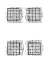
- FIGS. 10 ( a )- 10 ( p ) illustrate how pixel blocks of a preceding image are divided into 16 sets of pixel blocks in accordance with one embodiment of the present invention.
- Each of FIGS. 10 ( a )- 10 ( p ) shows the leading pixel block of each set of pixel blocks.
- the set corresponding to FIGS. 10 ( a )- 10 ( p ) are referred to as pixel block set A, pixel block set B, and pixel block set P, respectively.
- Each set of pixel blocks contains all pixel blocks in which the reference pixel of the pixel block is offset by a multiple of four vertically or horizontally from the reference pixel of the leading pixel block.
- leading pixel block A_ 1 of pixel block set A has reference pixel RP(0, 0).
- pixel block set A includes all pixel blocks having reference pixel RP(m, n), where m and n are multiples of 4.
- leading pixel block B_ 1 of pixel block set B has reference pixel RP(2, 0).
- pixel block set B includes all pixel blocks having reference pixel RP(m, n), where (m ⁇ 2) and n are multiples of 4.
- leading pixel block C_ 1 of pixel block set C has reference pixel RP(0, 2).
- pixel block set C includes all pixel blocks having reference pixel RP(m, n), where m and (n ⁇ 2) are multiples of 4.
- leading pixel block D_ 1 of pixel block set D has reference pixel RP(2, 2).
- pixel block set D includes all pixel blocks having reference pixel RP(m, n), where (m ⁇ 2) and (n ⁇ 2) are multiples of 4.
- leading pixel block E_ 1 of pixel block set E has reference pixel RP(1,0).
- pixel block set E includes all pixel blocks having reference pixel RP(m, n), where; (m ⁇ 1) and n are multiples of 4.
- leading pixel block F_ 1 of pixel block set F has reference pixel RP(3, 0).
- pixel block set F includes all pixel blocks having reference pixel RP(m, n), where (m ⁇ 3) and n are multiples of 4.
- leading pixel block G_ 1 of pixel block set G has reference pixel RP(1, 2).
- pixel block set G includes all pixel blocks having reference pixel RP(m, n), where (m ⁇ 1) and (n ⁇ 2) are multiples of 4.
- leading pixel block H_ 1 of pixel block set H has reference pixel RP(3, 2).
- pixel block set H includes all pixel blocks having reference pixel RP(m, n), where (m ⁇ 3) and (n ⁇ 2) are multiples of 4.
- leading pixel block I_ 1 of pixel block set I has reference pixel RP(0, 1).
- pixel block set I includes all pixel blocks having reference pixel RP(m, n), where m and (n ⁇ 1) are multiples of 4.
- leading pixel block J_ 1 of pixel block set J has reference pixel RP(2, 1).
- pixel block set J includes all pixel blocks having reference pixel RP(m, n), where (m ⁇ 2) and (n ⁇ 1) are multiples of 4.
- leading pixel block K_ 1 of pixel block set K has reference pixel RP(0, 3).
- pixel block set K includes all pixel blocks having reference pixel RP(m, n), where m and (n ⁇ 3) are multiples of 4.
- leading pixel block L_ 1 of pixel block set L has reference pixel RP(2, 3).
- pixel block set L includes all pixel blocks having reference pixel RP(m, n), where (m ⁇ 2) and (n ⁇ 3) are multiples of 4.
- leading pixel block M_ 1 of pixel block set M has reference pixel RP(1, 1).
- pixel block set M includes all pixel blocks having reference pixel RP(m, n), where (m ⁇ 1) and (n ⁇ 1) are multiples of 4.
- leading pixel block N_ 1 of pixel block set N has reference pixel RP(3, 1).
- pixel block set N includes all pixel blocks having reference pixel RP(m, n), where (m ⁇ 3) and (n ⁇ 1) are multiples; of 4.
- leading pixel block O_ 1 of pixel block set O has reference pixel RP(1,3).
- pixel block set O includes all pixel blocks having reference pixel RP(m, n), where (m ⁇ 1) and (n ⁇ 3) are multiples of 4.
- leading pixel block P_ 1 of pixel block set P has reference pixel RP(3, 3).
- pixel block set P includes all pixel blocks having reference pixel RP(m, n), where (m ⁇ 3) and (n ⁇ 3) are multiples of 4.
- FIG. 11 illustrates a method to further reduce the computational requirements of computing motion vectors.
- FIG. 11 shows a preceding image 1110 and an image 1120 of a video sequence.
- Image 1120 is divided into 16 ⁇ 16 macroblocks including macroblock 1125 , having reference pixel (x, y). Rather than comparing macroblock 1125 with all the possible pixel blocks in preceding image 1110 , macroblock 1125 is only compared with the pixel blocks within a search window 1115 . In general, smaller search windows can be used with video streams having very few fast moving objects.
- the coordinates of search window 1115 are determined by using the coordinates of macroblock 1125 .
- search window 1115 is centered around the coordinates of macroblock 1125 and includes 63 lines above and below the coordinates of macroblock 1125 and 31 columns on the left and right side of the coordinates of macroblock 1125 .
- Other embodiments of the present invention may define different search windows.
- a coarse search window and a fine search window are used.
- a coarse search window 1215 and a fine search window 1218 are defined in previous image 1110 .
- an embodiment of video encoder 700 uses only one fourth of the pixel blocks in coarse search window 1215 by skipping every other pixel block both vertically and horizontally.
- video encoder 700 would only compare macroblock 1125 with pixel blocks having reference pixels with coordinates of (m+2j, n+2k), where j and k are integers greater than or equal to zero.
- video encoder 700 uses every pixel block in fine search window 1218 .
- the top left coordinate of the coarse search window 1215 is equal to (x ⁇ 63, y ⁇ 31) and the bottom right coordinate is equal to (x+J+63, y+K+31), where J is the width and K is the height of a macroblock.
- the top left coordinate of the fine search window 1218 is equal to (x ⁇ 21, y ⁇ 12) and the bottom right coordinate is equal to (x+J+21, y+K+12), where J is the width and K is the height of a macroblock.
Landscapes
- Engineering & Computer Science (AREA)
- Multimedia (AREA)
- Signal Processing (AREA)
- Compression Or Coding Systems Of Tv Signals (AREA)
Abstract
Description
| TABLE 1 | |
| Previous Image | Current Image |
| (u + 3 − (u M 4), v + 4 − (v M 4)) | (x + 3 − (u M 4), y + 4 − (v M 4)) |
| (u + 3 − (u M 4), v + 7 − (v M 4)) | (x + 3 − (u M 4), y + 7 − (v M 4)) |
| (u + 3 − (u M 4), v + 12 − (v M 4)) | (x + 3 − (u M 4), y + 12 − (v M 4)) |
| (u + 3 − (u M 4), v + 15 − (v M 4)) | (x + 3 − (u M 4), y + 15 − (v M 4)) |
| (u + 7 − (u M 4), v + 4 − (v M 4)) | (x + 7 − (u M 4), y + 4 − (v M 4)) |
| (u + 7 − (u M 4), v + 7 − (v M 4)) | (x + 7 − (u M 4), y + 7 − (v M 4)) |
| (u + 7 − (u M 4), v + 12 − (v M 4)) | (x + 7 − (u M 4), y + 12 − (v M 4)) |
| (u + 7 − (u M 4), v + 15 − (v M 4)) | (x + 7 − (u M 4), y + 15 − (v M 4)) |
| (u + 11 − (u M 4), v + 4 − (v M 4)) | (x + 11 − (u M 4), y + 4 − (v M 4)) |
| (u + 11 − (u M 4), v + 7 − (v M 4)) | (x + 11 − (u M 4), y + 7 − (v M 4)) |
| (u + 11 − (u M 4), v + 12 − (v M 4)) | (x + 11 − (u M 4), y + 12 − (v M 4)) |
| (u + 11 − (u M 4), v + 15 − (v M 4)) | (x + 11 − (u M 4), y + 15 − (v M 4)) |
| (u + 15 − (u M 4), v + 4 − (v M 4)) | (x + 15 − (u M 4), y + 4 − (v M 4)) |
| (u + 15 − (u M 4), v + 7 − (v M 4)) | (x + 15 − (u M 4), y + 7 − (v M 4)) |
| (u + 15 − (u M 4), v + 12 − (v M 4)) | (x + 15 − (u M 4), y + 12 − (v M 4)) |
| (u + 15 − (u M 4), v + 15 − (v M 4)) | (x + 15 − (u M 4), y + 15 − (v M 4)) |
As explained above, second phase processing units 740A and 740B calculate difference measures of the predetermined pattern of FIG. 8(a). Thus, Second phase processing units 740A and 740B use the 64 pairs of the corresponding pixels in Table 2.
| TABLE 2 | |
| Previous Image | Current Image |
| (u + 1 − (u M 4), v + 0 − (v M 4)) | (x + 1 − (u M 4), y + 0 − (v M 4)) |
| (u + 1 − (u M 4), v + 3 − (v M 4)) | (x + 1 − (u M 4), y + 3 − (v M 4)) |
| (u + 1 − (u M 4), v + 4 − (v M 4)) | (x + 1 − (u M 4), y + 4 − (v M 4)) |
| (u + 1 − (u M 4), v + 7 − (v M 4)) | (x + 1 − (u M 4), y + 7 − (v M 4)) |
| (u + 1 − (u M 4), v + 8 − (v M 4)) | (x + 1 − (u M 4), y + 8 − (v M 4)) |
| (u + 1 − (u M 4), v + 11 − (v M 4)) | (x + 1 − (u M 4), y + 11 − (v M 4)) |
| (u + 1 − (u M 4), v + 12 − (v M 4)) | (x + 1 − (u M 4), y + 12 − (v M 4)) |
| (u + 1 − (u M 4), v + 15 − (v M 4)) | (x + 1 − (u M 4), y + 15 − (v M 4)) |
| (u + 3 − (u M 4), v + 0 − (v M 4)) | (x + 3 − (u M 4), y + 0 − (v M 4)) |
| (u + 3 − (u M 4), v + 3 − (v M 4)) | (x + 3 − (u M 4), y + 3 − (v M 4)) |
| (u + 3 − (u M 4), v + 4 − (v M 4)) | (x + 3 − (u M 4), y + 4 − (v M 4)) |
| (u + 3 − (u M 4), v + 7 − (v M 4)) | (x + 3 − (u M 4), y + 7 − (v M 4)) |
| (u + 3 − (u M 4), v + 8 − (v M 4)) | (x + 3 − (u M 4), y + 8 − (v M 4)) |
| (u + 3 − (u M 4), v + 11 − (v M 4)) | (x + 3 − (u M 4), y + 11 − (v M 4)) |
| (u + 3 − (u M 4), v + 12 − (v M 4)) | (x + 3 − (u M 4), y + 12 − (v M 4)) |
| (u + 3 − (u M 4), v + 15 − (v M 4)) | (x + 3 − (u M 4), y + 15 − (v M 4)) |
| (u + 5 − (u M 4), v + 0 − (v M 4)) | (x + 5 − (u M 4), y + 0 − (v M 4)) |
| (u + 5 − (u M 4), v + 3 − (v M 4)) | (x + 5 − (u M 4), y + 3 − (v M 4)) |
| (u + 5 − (u M 4), v + 4 − (v M 4)) | (x + 5 − (u M 4), y + 4 − (v M 4)) |
| (u + 5 − (u M 4), v + 7 − (v M 4)) | (x + 5 − (u M 4), y + 7 − (v M 4)) |
| (u + 5 − (u M 4), v + 8 − (v M 4)) | (x + 5 − (u M 4), y + 8 − (v M 4)) |
| (u + 5 − (u M 4), v + 11 − (v M 4)) | (x + 5 − (u M 4), y + 11 − (v M 4)) |
| (u + 5 − (u M 4), v + 12 − (v M 4)) | (x + 5 − (u M 4), y + 12 − (v M 4)) |
| (u + 5 − (u M 4), v + 15 − (v M 4)) | (x + 5 − (u M 4), y + 15 − (v M 4)) |
| (u + 7 − (u M 4), v + 0 − (v M 4)) | (x + 7 − (u M 4), y + 0 − (v M 4)) |
| (u + 7 − (u M 4), v + 3 − (v M 4)) | (x + 7 − (u M 4), y + 3 − (v M 4)) |
| (u + 7 − (u M 4), v + 4 − (v M 4)) | (x + 7 − (u M 4), y + 4 − (v M 4)) |
| (u + 7 − (u M 4), v + 7 − (v M 4)) | (x + 7 − (u M 4), y + 7 − (v M 4)) |
| (u + 7 − (u M 4), v + 8 − (v M 4)) | (x + 7 − (u M 4), y + 8 − (v M 4)) |
| (u + 7 − (u M 4), v + 11 − (v M 4)) | (x + 7 − (u M 4), y + 11 − (v M4)) |
| (u + 7 − (u M 4), v + 12 − (v M 4)) | (x + 7 − (u M 4), y + 12 − (v M 4)) |
| (u + 7 − (u M 4), v + 15 − (v M 4)) | (x + 7 − (u M 4), y + 15 − (v M 4)) |
| (u + 9 − (u M 4), v + 0 − (v M 4)) | (x + 9 − (u M 4), y + 0 − (v M 4)) |
| (u + 9 − (u M 4), v + 3 − (v M 4)) | (x + 9 − (u M 4), y + 3 − (v M 4)) |
| (u + 9 − (u M 4), v + 4 − (v M 4)) | (x + 9 − (u M 4), y + 4 − (v M 4)) |
| (u + 9 − (u M 4), v + 7 − (v M 4)) | (x + 9 − (u M 4), y + 7 − (v M 4)) |
| (u + 9 − (u M 4), v + 8 − (v M 4)) | (x + 9 − (u M 4), y + 8 − (v M 4)) |
| (u + 9 − (u M 4), v + 11 − (v M 4)) | (x + 9 − (u M 4), y + 11 − (v M 4)) |
| (u + 9 − (u M 4), v + 12 − (v M 4)) | (x + 9 − (u M 4), y + 12 − (v M 4)) |
| (u + 9 − (u M 4), v + 15 − (v M 4)) | (x + 9 − (u M 4), y + 15 − (v M 4)) |
| (u + 11 − (u M 4), v + 0 − (v M 4)) | (x + 11 − (u M 4), y + 0 − (v M 4)) |
| (u + 11 − (u M 4), v + 3 − (v M 4)) | (x + 11 − (u M 4), y + 3 − (v M 4)) |
| (u + 11 − (u M 4), v + 4 − (v M 4)) | (x + 11 − (u M 4), y + 4 − (v M 4)) |
| (u + 11 − (u M 4), v + 7 − (v M 4)) | (x + 11 − (u M 4), y + 7 − (v M 4)) |
| (u + 11 − (u M 4), v + 8 − (v M 4)) | (x + 11 − (u M 4), y + 8 − (v M 4)) |
| (u + 11 − (u M 4), v + 11 − (v M 4)) | (x + 11 − (u M 4), y + 11 − (v M 4)) |
| (u + 11 − (u M 4), v + 12 − (v M 4)) | (x + 11 − (u M 4), y + 12 − (v M 4)) |
| (u + 11 − (u M 4), v + 15 − (v M 4)) | (x + 11 − (u M 4), y + 15 − (v M 4)) |
| (u + 13 − (u M 4), v + 0 −(v M 4)) | (x + 13 − (u M 4), y + 0 − (v M 4)) |
| (u + 13 − (u M 4), v + 3 −(v M 4)) | (x + 13 − (u M 4), y + 3 − (v M 4)) |
| (u + 13 − (u M 4), v + 4 − (v M 4)) | (x + 13 − (u M 4), y + 4 − (v M 4)) |
| (u + 13 − (u M 4), v + 7 − (v M 4)) | (x + 13 − (u M 4), y + 7 − (v M 4)) |
| (u + 13 − (u M 4), v + 8 − (v M 4)) | (x + 13 − (u M 4), y + 8 − (v M 4)) |
| (u + 13 − (u M 4), v + 11 − (v M 4)) | (x + 13 − (u M 4), y + 11 − (v M 4)) |
| (u + 13 − (u M 4), v + 12 − (v M 4)) | (x + 13 − (u M 4), y + 12 − (v M 4)) |
| (u + 13 − (u M 4), v + 15 − (v M 4)) | (x + 13 − (u M 4), y + 15 − (v M 4)) |
| (u + 15 − (u M 4), v + 0 − (v M 4)) | (x + 15 − (u M 4), y + 0 − (v M 4)) |
| (u + 15 − (u M 4), v + 3 − (v M 4)) | (x + 15 − (u M 4), y + 3 − (v M 4)) |
| (u + 15 − (u M 4), v + 4 − (v M 4)) | (x + 15 − (u M 4), y + 4 − (v M 4)) |
| (u + 15 − (u M 4), v + 7 − (v M 4)) | (x + 15 − (u M 4), y + 7 − (v M 4)) |
| (u + 15 − (u M 4), v + 8 − (v M 4)) | (x + 15 − (u M 4), y + 8 − (v M 4)) |
| (u + 15 − (u M 4), v + 11 − (v M 4)) | (x + 15 − (u M 4), y + 11 − (v M 4)) |
| (u + 15 − (u M 4), v + 12 − (v M 4)) | (x + 15 − (u M 4), y + 12 − (v M 4)) |
| (u + 15 − (u M 4), v + 15 − (v M 4)) | (x + 15 − (u M 4), y + 15 − (v M 4)) |
Claims (9)
Priority Applications (1)
| Application Number | Priority Date | Filing Date | Title |
|---|---|---|---|
| US09/842,199 US6891890B1 (en) | 2001-04-24 | 2001-04-24 | Multi-phase motion estimation system and method |
Applications Claiming Priority (1)
| Application Number | Priority Date | Filing Date | Title |
|---|---|---|---|
| US09/842,199 US6891890B1 (en) | 2001-04-24 | 2001-04-24 | Multi-phase motion estimation system and method |
Publications (1)
| Publication Number | Publication Date |
|---|---|
| US6891890B1 true US6891890B1 (en) | 2005-05-10 |
Family
ID=34552956
Family Applications (1)
| Application Number | Title | Priority Date | Filing Date |
|---|---|---|---|
| US09/842,199 Expired - Fee Related US6891890B1 (en) | 2001-04-24 | 2001-04-24 | Multi-phase motion estimation system and method |
Country Status (1)
| Country | Link |
|---|---|
| US (1) | US6891890B1 (en) |
Cited By (2)
| Publication number | Priority date | Publication date | Assignee | Title |
|---|---|---|---|---|
| US20110249725A1 (en) * | 2010-04-09 | 2011-10-13 | Sony Corporation | Optimal separable adaptive loop filter |
| US20150256819A1 (en) * | 2012-10-12 | 2015-09-10 | National Institute Of Information And Communications Technology | Method, program and apparatus for reducing data size of a plurality of images containing mutually similar information |
Citations (11)
| Publication number | Priority date | Publication date | Assignee | Title |
|---|---|---|---|---|
| US5576772A (en) | 1993-09-09 | 1996-11-19 | Sony Corporation | Motion vector detection apparatus and method |
| US5587741A (en) | 1993-07-21 | 1996-12-24 | Daewoo Electronics Co., Ltd. | Apparatus and method for detecting motion vectors to half-pixel accuracy |
| EP0973336A2 (en) | 1998-07-15 | 2000-01-19 | Sony Corporation | Motion vector detecting, picture encoding and recording method and apparatus |
| US6154519A (en) * | 1998-02-17 | 2000-11-28 | U.S. Philips Corporation | Image processing method for motion estimation in a sequence of images, noise filtering method and medical imaging apparatus utilizing such methods |
| US6195389B1 (en) * | 1998-04-16 | 2001-02-27 | Scientific-Atlanta, Inc. | Motion estimation system and methods |
| US6259737B1 (en) | 1998-06-05 | 2001-07-10 | Innomedia Pte Ltd | Method and apparatus for fast motion estimation in video coding |
| US20010028680A1 (en) | 2000-04-11 | 2001-10-11 | Jean Gobert | Determining the degree of resemblance between a data sample and interpolations of other data samples |
| US20020015513A1 (en) | 1998-07-15 | 2002-02-07 | Sony Corporation | Motion vector detecting method, record medium on which motion vector calculating program has been recorded, motion detecting apparatus, motion detecting method, picture encoding apparatus, picture encoding method, motion vector calculating method, record medium on which motion vector calculating program has been recorded |
| US6414997B1 (en) * | 1998-03-20 | 2002-07-02 | Stmicroelectronics S.R.L. | Hierarchical recursive motion estimator for video images encoder |
| US6501446B1 (en) * | 1999-11-26 | 2002-12-31 | Koninklijke Philips Electronics N.V | Method of and unit for processing images |
| US6567469B1 (en) * | 2000-03-23 | 2003-05-20 | Koninklijke Philips Electronics N.V. | Motion estimation algorithm suitable for H.261 videoconferencing applications |
-
2001
- 2001-04-24 US US09/842,199 patent/US6891890B1/en not_active Expired - Fee Related
Patent Citations (11)
| Publication number | Priority date | Publication date | Assignee | Title |
|---|---|---|---|---|
| US5587741A (en) | 1993-07-21 | 1996-12-24 | Daewoo Electronics Co., Ltd. | Apparatus and method for detecting motion vectors to half-pixel accuracy |
| US5576772A (en) | 1993-09-09 | 1996-11-19 | Sony Corporation | Motion vector detection apparatus and method |
| US6154519A (en) * | 1998-02-17 | 2000-11-28 | U.S. Philips Corporation | Image processing method for motion estimation in a sequence of images, noise filtering method and medical imaging apparatus utilizing such methods |
| US6414997B1 (en) * | 1998-03-20 | 2002-07-02 | Stmicroelectronics S.R.L. | Hierarchical recursive motion estimator for video images encoder |
| US6195389B1 (en) * | 1998-04-16 | 2001-02-27 | Scientific-Atlanta, Inc. | Motion estimation system and methods |
| US6259737B1 (en) | 1998-06-05 | 2001-07-10 | Innomedia Pte Ltd | Method and apparatus for fast motion estimation in video coding |
| EP0973336A2 (en) | 1998-07-15 | 2000-01-19 | Sony Corporation | Motion vector detecting, picture encoding and recording method and apparatus |
| US20020015513A1 (en) | 1998-07-15 | 2002-02-07 | Sony Corporation | Motion vector detecting method, record medium on which motion vector calculating program has been recorded, motion detecting apparatus, motion detecting method, picture encoding apparatus, picture encoding method, motion vector calculating method, record medium on which motion vector calculating program has been recorded |
| US6501446B1 (en) * | 1999-11-26 | 2002-12-31 | Koninklijke Philips Electronics N.V | Method of and unit for processing images |
| US6567469B1 (en) * | 2000-03-23 | 2003-05-20 | Koninklijke Philips Electronics N.V. | Motion estimation algorithm suitable for H.261 videoconferencing applications |
| US20010028680A1 (en) | 2000-04-11 | 2001-10-11 | Jean Gobert | Determining the degree of resemblance between a data sample and interpolations of other data samples |
Cited By (3)
| Publication number | Priority date | Publication date | Assignee | Title |
|---|---|---|---|---|
| US20110249725A1 (en) * | 2010-04-09 | 2011-10-13 | Sony Corporation | Optimal separable adaptive loop filter |
| US8787449B2 (en) * | 2010-04-09 | 2014-07-22 | Sony Corporation | Optimal separable adaptive loop filter |
| US20150256819A1 (en) * | 2012-10-12 | 2015-09-10 | National Institute Of Information And Communications Technology | Method, program and apparatus for reducing data size of a plurality of images containing mutually similar information |
Similar Documents
| Publication | Publication Date | Title |
|---|---|---|
| US8098733B2 (en) | Multi-directional motion estimation using parallel processors and pre-computed search-strategy offset tables | |
| US7590180B2 (en) | Device for and method of estimating motion in video encoder | |
| US6269174B1 (en) | Apparatus and method for fast motion estimation | |
| KR100203913B1 (en) | Motion vector generator | |
| US5706059A (en) | Motion estimation using a hierarchical search | |
| US6859494B2 (en) | Methods and apparatus for sub-pixel motion estimation | |
| US6366317B1 (en) | Motion estimation using intrapixel logic | |
| KR20010071705A (en) | Motion estimation for digital video | |
| WO1998059497A1 (en) | Method for generating sprites for object-based coding systems using masks and rounding average | |
| US6934332B1 (en) | Motion estimation using predetermined pixel patterns and subpatterns | |
| EP0660615B1 (en) | Motion prediction processor and motion prediction apparatus | |
| JPH09261662A (en) | Method and device for estimating motion in digital video encoder | |
| US8184707B2 (en) | Method and apparatus for encoding multiview video using hierarchical B frames in view direction, and a storage medium using the same | |
| CN101873490B (en) | Image processing method and image information coding apparatus using the same | |
| US20050013367A1 (en) | Low complexity block size decision for variable block size motion estimation | |
| US6813315B1 (en) | Motion estimation using multiple search windows | |
| US6891890B1 (en) | Multi-phase motion estimation system and method | |
| WO1999009745A1 (en) | Motion estimation method and apparatus employing sub-sampling technique | |
| EP1461770A2 (en) | Image data retrieval | |
| US7773673B2 (en) | Method and apparatus for motion estimation using adaptive search pattern for video sequence compression | |
| US5539664A (en) | Process, apparatus, and system for two-dimensional caching to perform motion estimation in video processing | |
| US20050008077A1 (en) | Video compression method and apparatus | |
| US6925125B2 (en) | Enhanced aperture problem solving method using displaced center quadtree adaptive partitioning | |
| Ng et al. | A new fast motion estimation algorithm based on search window sub-sampling and object boundary pixel block matching | |
| US20050089099A1 (en) | Fast motion estimating apparatus |
Legal Events
| Date | Code | Title | Description |
|---|---|---|---|
| AS | Assignment |
Owner name: VWEB CORPORATION, CALIFORNIA Free format text: ASSIGNMENT OF ASSIGNORS INTEREST;ASSIGNORS:AUYEUNG, CHEUNG;CHEN, SHO LONG;SIU, STANLEY H.;REEL/FRAME:012494/0222 Effective date: 20011015 |
|
| AS | Assignment |
Owner name: SILICON VALLEY BANK, CALIFORNIA Free format text: SECURITY AGREEMENT;ASSIGNOR:VWEB CORPORATION;REEL/FRAME:016237/0269 Effective date: 20050624 |
|
| AS | Assignment |
Owner name: VWEB CORPORATION, CALIFORNIA Free format text: RELEASE BY SECURED PARTY;ASSIGNOR:SILICON VALLEY BANK;REEL/FRAME:017718/0446 Effective date: 20060307 |
|
| AS | Assignment |
Owner name: AGILITY CAPITAL, LLC, CALIFORNIA Free format text: SECURITY AGREEMENT;ASSIGNOR:VWEB CORPORATION;REEL/FRAME:019365/0660 Effective date: 20070601 |
|
| REMI | Maintenance fee reminder mailed | ||
| AS | Assignment |
Owner name: CRP STEVENS CREEK, L.L.C., CALIFORNIA Free format text: ASSIGNMENT OF ASSIGNORS INTEREST;ASSIGNOR:VWEB CORPORATION;REEL/FRAME:022619/0745 Effective date: 20090317 |
|
| REIN | Reinstatement after maintenance fee payment confirmed | ||
| FP | Lapsed due to failure to pay maintenance fee |
Effective date: 20090510 |
|
| FEPP | Fee payment procedure |
Free format text: PETITION RELATED TO MAINTENANCE FEES FILED (ORIGINAL EVENT CODE: PMFP); ENTITY STATUS OF PATENT OWNER: SMALL ENTITY |
|
| FEPP | Fee payment procedure |
Free format text: PETITION RELATED TO MAINTENANCE FEES GRANTED (ORIGINAL EVENT CODE: PMFG); ENTITY STATUS OF PATENT OWNER: SMALL ENTITY |
|
| FPAY | Fee payment |
Year of fee payment: 4 |
|
| SULP | Surcharge for late payment | ||
| PRDP | Patent reinstated due to the acceptance of a late maintenance fee |
Effective date: 20100607 |
|
| REMI | Maintenance fee reminder mailed | ||
| LAPS | Lapse for failure to pay maintenance fees | ||
| STCH | Information on status: patent discontinuation |
Free format text: PATENT EXPIRED DUE TO NONPAYMENT OF MAINTENANCE FEES UNDER 37 CFR 1.362 |
|
| FP | Lapsed due to failure to pay maintenance fee |
Effective date: 20130510 |