US688081A - Harrow. - Google Patents
Harrow. Download PDFInfo
- Publication number
- US688081A US688081A US5923801A US1901059238A US688081A US 688081 A US688081 A US 688081A US 5923801 A US5923801 A US 5923801A US 1901059238 A US1901059238 A US 1901059238A US 688081 A US688081 A US 688081A
- Authority
- US
- United States
- Prior art keywords
- arms
- shifting
- shaft
- frame
- pedestals
- Prior art date
- Legal status (The legal status is an assumption and is not a legal conclusion. Google has not performed a legal analysis and makes no representation as to the accuracy of the status listed.)
- Expired - Lifetime
Links
Images


Classifications
-
- A—HUMAN NECESSITIES
- A01—AGRICULTURE; FORESTRY; ANIMAL HUSBANDRY; HUNTING; TRAPPING; FISHING
- A01B—SOIL WORKING IN AGRICULTURE OR FORESTRY; PARTS, DETAILS, OR ACCESSORIES OF AGRICULTURAL MACHINES OR IMPLEMENTS, IN GENERAL
- A01B29/00—Rollers
- A01B29/04—Rollers with non-smooth surface formed of rotatably-mounted rings or discs or with projections or ribs on the roller body; Land packers
- A01B29/048—Bar cage rollers
Definitions
- the purpose of the invention is to provide a simple, durable, and economic form of harrow which will harrow and roll the ground at one operation and to provide a rapidly-moving barrow-frame driven from the axle of the machine, effecting a rapid and thorough pulverization of the ground.
- Afurtherpurpose of the invention is to provide a novel and simple form of steering-gear under complete control of the driver and means whereby the barrow-drum and roller may be simultaneously raised and lowered and whereby when the barrow-drum is elevated it will be simultaneously thrown out of gear with the driving mechanism.
- Figure 1 is a plan View of the improved Fig. 2 is a side elevation of the same.
- Fig. 3 is a detail section illustrating ,one of the carrying-arms forthe barrow-drum axle and transmitting-gears, the transmitting-gears being shown out of mesh with the driving-gear, the section being takenpractically on the line 3 3 of Fig. 4.
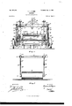
- Fig. 4 is a section taken practically on the line 4 4 of Fig. 2
- Fig. 5 is a section taken practically on the line 5 5 of Fig. 2.
- the frame of the machine consists of two side bars 10, connected by any suitable number of cross-bars 11, as shown in Fig. 1, and downwardly-extending members 12, which are secured to the forward ends of the side bars 10, which members 12 at their lower ends carry bearings 13, in which the forward axle ,14 is mounted to revolve, the axle being provided with supporting-wheels 15 at its outer ends of suitable diameter.
- ent members 12 are connected at their lower ends by a front cross-bar 16, from which crossbar 'a forward extension 17 is carried, and this extension receives a tongue 18, which is provided with the usual draft-tree 19, connected with the frame on the axle by means of chains 20.
- Pedestals 21, provided at their upper ends with horizontal members 21a, are bolted to the outer faces of the side bars 10 between the center ⁇ of the frame and its rear extremity, and these pedestals 21 are provided with longitudinal slots 22, having upwardly and rearwardly inclined extensions 22 at their upper ends, as is best shown in Fig. 3.
- the ends of a shaft 23 are located in the slots 22 of the pedcstals 2l, and, as shown in Fig. 4, a drum A is secured to the said shaft 23, which drum consists of suitable heads 24, fast to the axle, ⁇ and cross-bars 25, which connect the heads.
- These crossbars 25 carry teeth 26 of suitable construction secured to the cross-bars in any approved manner.
- each shifting arm B is preferably made in two sections-a rear section b and a forward section b'-the two sections having a hinged connection 28. At the rear end of the rear section of each shifting arm a downwardly-.ex-
- tending block 27 is made integral with then arm or is attached thereto, and the ends of the shaft 23 which project beyond the harrow-drum A are loosely passed through suitable openings in these blocks, as is best shown in Fig. 4.
- a head 29 is formed, having a longitudinal slot 30 produced therein, and the forward axle 14 of the machine is passed through the slots 30 in the heads 29 of the said shifting arms, so that the forward ends of the shifting arms are supported by the for ward axle 14, and the said arms have sliding movement on the said forward axle.
- the harrow-drum A is driven by securing to the forward axle 14 outside of the frame, near each end, a gear 31, and these gears are adapted to mesh with pinions 32, secured upon the outer ends of the shaft 33, which shaft is held to turn in an enlarged portion of the forward section b of each shifting arm B.
- the shaft 33 is provided also near each end out- ICO . side of the frame with a sprocket-wheel 34,
- each of the shifting rods 37 a hand-wheel 38 is preferably secured for the purpose of turning lthese rods, and the hand-wheels 38a are within convenient reach of the drivers seat 39, which seat is supported uponfa foot-rest 40 by means of a suitable standard.
- the foot-rest extends from one side bar of the frame to the other, as is shown in Fig. 1.
- Sockets 46 are formed on the outer faces of the .pedestals 2 1 near their up- ;per'ends, and at 'the lower portions of vthe said pedestals outwardly-extending knuckles 47 are provided.
- a headblock 53 is secured at its center, and the ends y e and in .positive lines in Fig. 3.
- the shiftingr arms B are supported between 1 their ends by rods 41, and these rods 'are passed up through lbearing 42 at lthe outer side 'of the side bars of the frame, as shown i in Fig. 2, the said rods being pivotally at-g tached to the shifting arms vat their lowerl Their upper portions are 'threaded' -and Ahand-wheels 44 are located upon the lupespsi of these head-blocks are pivotally connected by rods 54 and 55.
- the forward rod 54 at its center is provided with a pin 56, which enters a slot 57 in a lever 58, fulcrumed upon one of the cross-bars 11, as is illustrated in Fig. 4, and the lever is provided with a thumb-latch 58, which enters recesses in a rack 59, secured to the said cross-bar 11.
- a roller 60 is located capable of traveling on the ground, and this roller when not needed is raised from the ground simultaneously with the elevation of the barrow-drum A.
- the roller 60 is provided with trunnions which are mounted in bearings 61, and these bearings are pivotally attached to arms 62, which armsvextend up through sleeves 63, .pivotally mounted in brackets 64 at the sides of the rear portion of the frame.
- Springs 65 are coiled around the arms 62, having bearing against the bottom portion of the sleeves and against collars 66, adjustable on the said arms 62, as is shown in Figs. 2 and 5. By adjusting the collars 66 the roller 60 may -be made to bear with more or less pressure on the ground.
- Auxiliary arms 67 are attached to the bearings 61 for the roller-trunnions, las shown in Fig. 2,.and these arms are pivotally connected with the rear ends of the shifting arms 13 just above inclined shoulders 68, formed at the ⁇ upper rear portions of the pivot-blocks 27 for the arms, as is shown in dotted lines in Fig. 2
- the roller 60 is also raised, as at the first upward movement of the rear portions of the shifting arms, the arms 67, connected with the roller, will bear upon the vinclined shoulders 68. Consequently the auxiliary arms of the roller lwill be carried upward by the shifting arms, Vtaking the roller 60 with them.
- roller drops tothe ground when the harrowdrum is lowered.
- collars 66 may be adj usted by set-screws said collars may be threaded on the arms 62.
- shifting arms pivotally and slidably mounted esosi slots in the pedestals, the shaft being carried by the shifting arms, a harrow-drum secured to the said shaft, means for rotating the shaft from an axle of the machine, and devices for raising and lowering that portion of the shifting arms carrying the shaft for the harrowdrum, as set forth.
- the combination with a whee1supported frame, and shifting arms pivotally and slidably mounted on the forward axle of the machine, said arms being constructed in pivotally-connected sections, of pedestals extending downward from the frame, provided with longitudinal slots therein, a shaft carried by the shifting arms and passed through the slots in the pedestals, a barrow-drum secured to the said shaft, a driven shaft also carried by the shifting arms, gear connections between the driven shaft and the forward axle of the machine, and a driving connection between the driven shaft and the shaft carrying the harroW-drum, and devices for raising and lowering the shifting arms, for the purpose described.
- the combination with a wheel-supported frame, and shifting arms pivotally and slidably mounted on the forward axle of the machine, said arms being constructed in pivotally-connected sections, of pedestals extending downward from the frame, provided with longitudinal slots therein, a shaft carried by the shifting arms and passed through the slots in the pedestals, a barrow-drum secured to the said shaft, a driven shaft also carried by the shifting arms, gear connections between the driven shaft and the forward axle of the machine, a driving connection between the driven shaft and the shaft carrying the harrowdrum, devices for raising and lowering the shifting arms, a roller, arms extending from the bearings of the roller, which arms are pivotally connected with the shifting arms, and a tension device connected with the said roller and having a rocking connection with the said frame, as described.
- the combination with a wheel-supported frame, shifting arms pivotally and slidably mounted upon the axle of the said frame, pedestals extending down from the frame, a shaft mounted in the shift ing arms, a barrow-drum secured to said shaft, and means for raising and lowering that portion of the shifting arms carrying the shaft, of rocking bearings at the rear of the frame, a roller, arms extending from the bearings of the roller and connected with the shifting arms, tension -arms pivotally connected with the bearings of the roller and extending loosely through the rocking bearings, and springs adj ustably located on the tension-arms, having bearing against the said bearings, substantially as described.
Description
Patented Dec. 3, |901.
T. L. FLYNN.
`3 Sheets-Sheet I.
(No Model.)
NQLH
iQ SS @MFA n ,l -w31 Ihm RNb u lll.: l, o mk QW NN hat IL .1w km.
Wl TNE SSE S A77 NEYS TH: Noims Fn'ms Co. PHoTaLlTNo.. wllsmmacu4 nA c.
No. 683,081. Patented nec. 3, lem.
T. L. FLYNN.
HARnow.
(Application led May 8, 1901.) (No Model.) 3 Sheets-Sheet 2.
W/ TNE SSE S A TTHNE YS No. 638,08l. Patented Dec. 3, |901.
T. L. FLYNN.
HARBDW.
(Application led. May B, 1901.) V (No Mndel.) 3 Sheets-$heet 3.
machine.
NTTED STATES PATENT OFFICE.
THOMAS L. FLYNN, OF NEV YORK, N. Y.
HARROW.`
sPncIFIcATIo forming part of Letters Patent Ne. 688,081, dated December 3, 1901.
Application filed May 8, 1901.
To @ZZ whom zit may concern,.-
Beit known that I, THOMAS L. FLYNN, a citizen of the United States, and a resident of the city ofNew York, borough of the Bronx, in the county and State of New York, have invented a new and Improved Harrow, of which the following is a full, clear, and exact description.
The purpose of the invention is to provide a simple, durable, and economic form of harrow which will harrow and roll the ground at one operation and to provide a rapidly-moving barrow-frame driven from the axle of the machine, effecting a rapid and thorough pulverization of the ground.
Afurtherpurpose of the invention is to provide a novel and simple form of steering-gear under complete control of the driver and means whereby the barrow-drum and roller may be simultaneously raised and lowered and whereby when the barrow-drum is elevated it will be simultaneously thrown out of gear with the driving mechanism.
The invention consists in the novel construction and combination of the several parts, as will be hereinafter fully set forth, and pointed out in the claims.
Reference is to be had to the accompanying drawings, forminga part of this specification, in which similar characters of reference indicate corresponding parts in all the figures.
Figure 1 is a plan View of the improved Fig. 2 is a side elevation of the same. Fig. 3 is a detail section illustrating ,one of the carrying-arms forthe barrow-drum axle and transmitting-gears, the transmitting-gears being shown out of mesh with the driving-gear, the section being takenpractically on the line 3 3 of Fig. 4. Fig. 4 is a section taken practically on the line 4 4 of Fig. 2, and Fig. 5 is a section taken practically on the line 5 5 of Fig. 2.
The frame of the machine consists of two side bars 10, connected by any suitable number of cross-bars 11, as shown in Fig. 1, and downwardly-extending members 12, which are secured to the forward ends of the side bars 10, which members 12 at their lower ends carry bearings 13, in which the forward axle ,14 is mounted to revolve, the axle being provided with supporting-wheels 15 at its outer ends of suitable diameter. The forward pend- Serial No. 59,238.. (No model.)
Two shifting arms B are employed, located outside of the frame structure. One of these shifting arms is shown in detail in Fig. 3, and each shifting arm is preferably made in two sections-a rear section b and a forward section b'-the two sections having a hinged connection 28. At the rear end of the rear section of each shifting arm a downwardly-.ex-
tending block 27 is made integral with then arm or is attached thereto, and the ends of the shaft 23 which project beyond the harrow-drum A are loosely passed through suitable openings in these blocks, as is best shown in Fig. 4. At the forward end of each shifting arm B a head 29 is formed, having a longitudinal slot 30 produced therein, and the forward axle 14 of the machine is passed through the slots 30 in the heads 29 of the said shifting arms, so that the forward ends of the shifting arms are supported by the for ward axle 14, and the said arms have sliding movement on the said forward axle.
The harrow-drum A is driven by securing to the forward axle 14 outside of the frame, near each end, a gear 31, and these gears are adapted to mesh with pinions 32, secured upon the outer ends of the shaft 33, which shaft is held to turn in an enlarged portion of the forward section b of each shifting arm B. The shaft 33 is provided also near each end out- ICO . side of the frame with a sprocket-wheel 34,
and these sprocket-wheels 34 are connected by chain belts 35 with sprocket-wheels 36, secured upon the shaft 23 of the harrow-drum between the pedestals 21 and the shifting arms B, as is shown in Fig. 4. The shifting.
arms are raised or lowered through the medium of rods 37, having a swivel connection with the rear members h of the shifting arms B, near their rear ends, and the upper portions of the rods 37 are threaded. The threaded portions of the rods 37 pass through nuts 38, which nuts are pivoted by means of suitable trunnions in the top sections 21? of the pedestals 21, as is shown in Figs. 1 and 4. At the upper end of each of the shifting rods 37 a hand-wheel 38 is preferably secured for the purpose of turning lthese rods, and the hand-wheels 38a are within convenient reach of the drivers seat 39, which seat is supported uponfa foot-rest 40 by means of a suitable standard. The foot-rest extends from one side bar of the frame to the other, as is shown in Fig. 1.
It will be observed that when the rear ends of the shifting arms are raised to the position shown in Fig. 3 the shifting arms move not only upward at their rear ends, but likewise rearwardly as theshaft`23 of the barrow-drum enters 'the inclined extensions 22 of the slots ifn the pedestals, and at Vsuch time the shifting arms are carried bodily rearward and the?Il Irpinions 32 are carried out of mesh with the gears 31 on ythe forward axle, thus stopping Vthe revolution of the harrow-drum while it isi elevated.
ends.
-per threaded ends of the rods, and by adjusting the rods 41 the pinions 32 may have greater or less lfrictional engagement with vthe driving-gears 31. Sockets 46 are formed on the outer faces of the .pedestals 2 1 near their up- ;per'ends, and at 'the lower portions of vthe said pedestals outwardly-extending knuckles 47 are provided. Vertical shafts 48 areipassed at their lower ends through the knuckles 47 of the pedestals and through knuckles 49, which are Alocated between the knuckles 47, which knuckles 49 are secured to vertical members 50, forming a portion of the vlower parts of the shafts 48,'asshownrin Fig. 4. The stub-axles upon which the rear wheels 51 are mounted are secured to the said members 50. Thus it will'be observedfby turning the shafts 48 the rear wheels will be turned also and the machine may be steered. The shafts 48 'are .prevented from vmoving upward `by placing collars 52 on the shafts below the sockets 46.
At the upper end of veach shaft 48 a headblock 53 is secured at its center, and the ends y e and in .positive lines in Fig. 3.
The shiftingr arms B are supported between 1 their ends by rods 41, and these rods 'are passed up through lbearing 42 at lthe outer side 'of the side bars of the frame, as shown i in Fig. 2, the said rods being pivotally at-g tached to the shifting arms vat their lowerl Their upper portions are 'threaded' -and Ahand-wheels 44 are located upon the lupespsi of these head-blocks are pivotally connected by rods 54 and 55. The forward rod 54 at its center is provided with a pin 56, which enters a slot 57 in a lever 58, fulcrumed upon one of the cross-bars 11, as is illustrated in Fig. 4, and the lever is provided with a thumb-latch 58, which enters recesses in a rack 59, secured to the said cross-bar 11. Thus by moving the lever 58 to the right or to the left the machine may be made to travel in any desired direction.
At the rear end of the machine a roller 60 is located capable of traveling on the ground, and this roller when not needed is raised from the ground simultaneously with the elevation of the barrow-drum A. The roller 60 is provided with trunnions which are mounted in bearings 61, and these bearings are pivotally attached to arms 62, which armsvextend up through sleeves 63, .pivotally mounted in brackets 64 at the sides of the rear portion of the frame. Springs 65 are coiled around the arms 62, having bearing against the bottom portion of the sleeves and against collars 66, adjustable on the said arms 62, as is shown in Figs. 2 and 5. By adjusting the collars 66 the roller 60 may -be made to bear with more or less pressure on the ground. Auxiliary arms 67 are attached to the bearings 61 for the roller-trunnions, las shown in Fig. 2,.and these arms are pivotally connected with the rear ends of the shifting arms 13 just above inclined shoulders 68, formed at the `upper rear portions of the pivot-blocks 27 for the arms, as is shown in dotted lines in Fig. 2 When 'the rear ends of the shifting arms B are raised, carrying the barrow-drum up with them,'the roller 60 is also raised, as at the first upward movement of the rear portions of the shifting arms, the arms 67, connected with the roller, will bear upon the vinclined shoulders 68. Consequently the auxiliary arms of the roller lwill be carried upward by the shifting arms, Vtaking the roller 60 with them. The
roller drops tothe ground when the harrowdrum is lowered. Instead of the collars 66 being adj usted by set-screws said collars may be threaded on the arms 62.
Having thus described my invention, I claim as new and desire to secure by Letters Patent-- 1. Ina harrow, a Wheel-supported frame, pedestals extending downward from the frame, shifting arms pivotally and slidably mounted upon one of the axles, a shaft carried by the shifting arms, having guided movement in said pedestals, and means for raising and lowering the shifting arms at that point where the shaft is guided by the pedestals, as described.
2. In a. harrow, a Wheel-supported frame,
shifting arms pivotally and slidably mounted esosi slots in the pedestals, the shaft being carried by the shifting arms, a harrow-drum secured to the said shaft, means for rotating the shaft from an axle of the machine, and devices for raising and lowering that portion of the shifting arms carrying the shaft for the harrowdrum, as set forth.
3. In harrows, the combination, with a whee1supported frame, and shifting arms pivotally and slidably mounted on the forward axle of the machine, said arms being constructed in pivotally-connected sections, of pedestals extending downward from the frame, provided with longitudinal slots therein, a shaft carried by the shifting arms and passed through the slots in the pedestals, a barrow-drum secured to the said shaft, a driven shaft also carried by the shifting arms, gear connections between the driven shaft and the forward axle of the machine, and a driving connection between the driven shaft and the shaft carrying the harroW-drum, and devices for raising and lowering the shifting arms, for the purpose described.
4. In harrows, the combination, with a wheel-supported frame, and shifting arms pivotally and slidably mounted on the forward axle of the machine, said arms being constructed in pivotally-connected sections, of pedestals extending downward from the frame, provided with longitudinal slots therein, a shaft carried by the shifting arms and passed through the slots in the pedestals, a barrow-drum secured to the said shaft, a driven shaft also carried by the shifting arms, gear connections between the driven shaft and the forward axle of the machine, a driving connection between the driven shaft and the shaft carrying the harrowdrum, devices for raising and lowering the shifting arms, a roller, arms extending from the bearings of the roller, which arms are pivotally connected with the shifting arms, and a tension device connected with the said roller and having a rocking connection with the said frame, as described.
5. In harrows, the combination, with a wheel-supported frame, shifting arms pivotally and slidably mounted upon the axle of the said frame, pedestals extending down from the frame, a shaft mounted in the shift ing arms, a barrow-drum secured to said shaft, and means for raising and lowering that portion of the shifting arms carrying the shaft, of rocking bearings at the rear of the frame, a roller, arms extending from the bearings of the roller and connected with the shifting arms, tension -arms pivotally connected with the bearings of the roller and extending loosely through the rocking bearings, and springs adj ustably located on the tension-arms, having bearing against the said bearings, substantially as described.
In testimony whereof I have signed my name to this specification in the presence of two subscribing witnesses. 'l
THOMAS L. FLYNN.
Witnesses:
J. FRED. ACKER, JNO. M. RITTER@
Priority Applications (1)
| Application Number | Priority Date | Filing Date | Title |
|---|---|---|---|
| US5923801A US688081A (en) | 1901-05-08 | 1901-05-08 | Harrow. |
Applications Claiming Priority (1)
| Application Number | Priority Date | Filing Date | Title |
|---|---|---|---|
| US5923801A US688081A (en) | 1901-05-08 | 1901-05-08 | Harrow. |
Publications (1)
| Publication Number | Publication Date |
|---|---|
| US688081A true US688081A (en) | 1901-12-03 |
Family
ID=2756623
Family Applications (1)
| Application Number | Title | Priority Date | Filing Date |
|---|---|---|---|
| US5923801A Expired - Lifetime US688081A (en) | 1901-05-08 | 1901-05-08 | Harrow. |
Country Status (1)
| Country | Link |
|---|---|
| US (1) | US688081A (en) |
Cited By (1)
| Publication number | Priority date | Publication date | Assignee | Title |
|---|---|---|---|---|
| WO2005062919A2 (en) * | 2003-12-22 | 2005-07-14 | Wachovia Corporation | Public key encryption for groups |
-
1901
- 1901-05-08 US US5923801A patent/US688081A/en not_active Expired - Lifetime
Cited By (2)
| Publication number | Priority date | Publication date | Assignee | Title |
|---|---|---|---|---|
| WO2005062919A2 (en) * | 2003-12-22 | 2005-07-14 | Wachovia Corporation | Public key encryption for groups |
| WO2005062919A3 (en) * | 2003-12-22 | 2005-08-25 | Wachovia Corp | Public key encryption for groups |
Similar Documents
| Publication | Publication Date | Title |
|---|---|---|
| US688081A (en) | Harrow. | |
| US661307A (en) | Implement for cultivating land. | |
| US401285A (en) | Potato-digger | |
| US1026912A (en) | Reversible harrow. | |
| US654354A (en) | Cultivator. | |
| US662366A (en) | Clod-crusher and sod-cutter. | |
| US302370A (en) | Steam-plow | |
| US517047A (en) | Steam-plow | |
| US826418A (en) | Rolling-disk cultivator. | |
| US1235456A (en) | Grading-machine. | |
| US1556643A (en) | Farm machine | |
| US251513A (en) | benson | |
| US988315A (en) | Implement for plowing and otherwise cultivating land. | |
| US618400A (en) | Clod-crusher | |
| US1059936A (en) | Cotton chopper and cultivator. | |
| US382983A (en) | ing-leton | |
| US608121A (en) | Harrow | |
| US818252A (en) | Cultivator. | |
| US995553A (en) | Cotton chopper and scraper. | |
| US1196088A (en) | Opebating hbams eos | |
| US499211A (en) | Rotary cultivator | |
| US660698A (en) | Listed-corn cultivator. | |
| US179427A (en) | Improvement in rotary harrows | |
| US790721A (en) | Plow. | |
| US552886A (en) | beadshaw |