US6845606B2 - Variable cycle propulsion system with gas tapping for a supersonic airplane, and a method of operation - Google Patents
Variable cycle propulsion system with gas tapping for a supersonic airplane, and a method of operation Download PDFInfo
- Publication number
- US6845606B2 US6845606B2 US10/167,602 US16760202A US6845606B2 US 6845606 B2 US6845606 B2 US 6845606B2 US 16760202 A US16760202 A US 16760202A US 6845606 B2 US6845606 B2 US 6845606B2
- Authority
- US
- United States
- Prior art keywords
- engine
- propulsion assembly
- engines
- supersonic
- exhaust gas
- Prior art date
- Legal status (The legal status is an assumption and is not a legal conclusion. Google has not performed a legal analysis and makes no representation as to the accuracy of the status listed.)
- Expired - Lifetime
Links
Images


Classifications
-
- F—MECHANICAL ENGINEERING; LIGHTING; HEATING; WEAPONS; BLASTING
- F02—COMBUSTION ENGINES; HOT-GAS OR COMBUSTION-PRODUCT ENGINE PLANTS
- F02K—JET-PROPULSION PLANTS
- F02K3/00—Plants including a gas turbine driving a compressor or a ducted fan
- F02K3/02—Plants including a gas turbine driving a compressor or a ducted fan in which part of the working fluid by-passes the turbine and combustion chamber
- F02K3/04—Plants including a gas turbine driving a compressor or a ducted fan in which part of the working fluid by-passes the turbine and combustion chamber the plant including ducted fans, i.e. fans with high volume, low pressure outputs, for augmenting the jet thrust, e.g. of double-flow type
- F02K3/075—Plants including a gas turbine driving a compressor or a ducted fan in which part of the working fluid by-passes the turbine and combustion chamber the plant including ducted fans, i.e. fans with high volume, low pressure outputs, for augmenting the jet thrust, e.g. of double-flow type controlling flow ratio between flows
-
- F—MECHANICAL ENGINEERING; LIGHTING; HEATING; WEAPONS; BLASTING
- F02—COMBUSTION ENGINES; HOT-GAS OR COMBUSTION-PRODUCT ENGINE PLANTS
- F02K—JET-PROPULSION PLANTS
- F02K3/00—Plants including a gas turbine driving a compressor or a ducted fan
- F02K3/02—Plants including a gas turbine driving a compressor or a ducted fan in which part of the working fluid by-passes the turbine and combustion chamber
- F02K3/025—Plants including a gas turbine driving a compressor or a ducted fan in which part of the working fluid by-passes the turbine and combustion chamber the by-pass flow being at least partly used to create an independent thrust component
-
- F—MECHANICAL ENGINEERING; LIGHTING; HEATING; WEAPONS; BLASTING
- F02—COMBUSTION ENGINES; HOT-GAS OR COMBUSTION-PRODUCT ENGINE PLANTS
- F02K—JET-PROPULSION PLANTS
- F02K3/00—Plants including a gas turbine driving a compressor or a ducted fan
- F02K3/12—Plants including a gas turbine driving a compressor or a ducted fan characterised by having more than one gas turbine
-
- Y—GENERAL TAGGING OF NEW TECHNOLOGICAL DEVELOPMENTS; GENERAL TAGGING OF CROSS-SECTIONAL TECHNOLOGIES SPANNING OVER SEVERAL SECTIONS OF THE IPC; TECHNICAL SUBJECTS COVERED BY FORMER USPC CROSS-REFERENCE ART COLLECTIONS [XRACs] AND DIGESTS
- Y02—TECHNOLOGIES OR APPLICATIONS FOR MITIGATION OR ADAPTATION AGAINST CLIMATE CHANGE
- Y02T—CLIMATE CHANGE MITIGATION TECHNOLOGIES RELATED TO TRANSPORTATION
- Y02T50/00—Aeronautics or air transport
- Y02T50/60—Efficient propulsion technologies, e.g. for aircraft
Definitions
- the present invention relates to a variable cycle propulsion system for a supersonic airplane making it possible both to obtain high thrust and a large bypass ratio for takeoff, landing, and subsonic cruising flight so as to greatly reduce and improve specific consumption during these stages of flight, and also to obtain a high exhaust speed adapted to supersonic cruising flight.
- the invention relates to a propulsion system having auxiliary fans separate from the engines and adapted to subsonic flight (in terms both of noise and fuel consumption).
- variable cycle propulsion system in another aspect of the invention, it also relates to a method of operating said variable cycle propulsion system.
- supersonic airplane engines must also satisfy requirements of low engine pod drag during supersonic cruising, low specific fuel consumption while overflying inhabited areas at subsonic cruising speed, and reduced emissions of nitrogen oxide pollution close to the ozone layer at high altitude.
- variable cycle engine for supersonic airplane propulsion.
- that type of engine takes up two different configurations: one for subsonic cruising flight, takeoff, and landing; and the other for supersonic cruising flight, given the degree of incompatibility between those two stages of flight in terms of engine operation.
- Noise level depends on gas exhaust speed, and to reduce noise to an acceptable level, exhaust speed must nowadays be less than 400 meters per second (m/s), which corresponds to a threshold of 103 decibels (dB) (with new regulations reducing this to 300 m/s or 90 dB as from the year 2006).
- m/s meters per second
- dB decibels
- Such an exhaust speed thus implies an engine having low specific thrust, which corresponds to a large bypass ratio, i.e. a high level of drag when cruising at supersonic speed.
- variable cycle engines proposed by manufacturers seek to combine low engine noise during takeoff and landing, low specific fuel consumption during subsonic cruising, and high specific thrust during high altitude supersonic cruising.
- variable cycle engine designs are known, however varying the bypass ratio of such designs does not enable good optimization both in the subsonic configuration and in the supersonic configuration.
- Adopting a gas exhaust speed equal to or less than 400 m/s requires an engine pod of large diameter, and all variable cycle engines known at present thus require a pod front section that is greater than the optimum section for supersonic cruising flight.
- U.S. Pat. No. 5,529,263 discloses a supersonic airplane having a propulsion assembly for takeoff, landing, and subsonic cruising flight, and two engines adapted for supersonic cruising flight.
- the propulsion assembly is constituted by retractable high-bypass ratio booster turbojets, which presents numerous drawbacks, in particular concerning bulk and weight for the airplane.
- the present invention thus seeks to mitigate such drawbacks by proposing a variable cycle propulsion system for supersonic airplanes in which the subsonic and supersonic configurations are well separated, in particular by using one or more separate auxiliary fans of large diameter that are optionally retractable during supersonic cruising flight.
- the invention also proposes a method of operating such a propulsion system.
- the invention provides a variable cycle propulsion system for a supersonic airplane, the system comprising at least one engine having means for producing exhaust gas and a gas exhaust nozzle for generating thrust for supersonic flight speeds, and at least one separate auxiliary propulsion assembly dissociated from said engine, having no gas generator, and capable of generating thrust for takeoff, landing, and subsonic flight speeds, said system further comprising gas flow tapping means movable between a position in which they tap off at least a fraction of the exhaust gas produced by said engine and feed it to said propulsion assembly to enable it to generate thrust for takeoff, landing, and subsonic cruising flight, and a position in which the gas produced by the engine is directed solely to the engine nozzle for supersonic cruising flight.
- the propulsion assembly dedicated to takeoff, landing, and subsonic cruising flight uses resources (gas generator) of the engines that are dedicated to supersonic cruising flight.
- Said propulsion assembly comprises one or more fans driven by gas tapped from the engine(s).
- the fans can be housed within the airplane fuselage or they can be retractable, thus enabling them to be of dimensions sufficient for producing the necessary thrust with a high bypass ratio, while nevertheless retaining low drag in supersonic flight.
- FIGS. 1A and 1B are diagrammatic views of a first embodiment of a propulsion system of the invention respectively in its configuration for takeoff, landing, and subsonic cruising flight, and in its configuration for supersonic cruising flight;
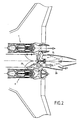
- FIG. 2 is a fragmentary longitudinal section view of a supersonic airplane including the FIG. 1 system and shown in both configurations of use;
- FIG. 3 is a diagrammatic perspective view of an airplane including a propulsion system constituting a second embodiment of the invention.
- FIGS. 1A and 1B are diagrammatic longitudinal section views through a system constituting a first embodiment of the invention, it can be seen that the system is constituted in particular by two engines 1 and 1 ′. These engines are conventionally disposed in low-drag pads (not shown) which are generally connected to the bottom faces of the wings of an airplane, but which could equally well be installed on the top faces of the wings.
- each engine can be of the single-flow type, having one, two or three shafts, or of the double-flow type, having one, two or three shafts.
- each engine comprises an air intake 2 , a compressor section 4 , a combustion chamber 6 , a turbine section 8 , and a combustion gas exhaust section 10 .
- the engines are also dimensioned optimally for supersonic cruising flight (the period involving the longest flying time).
- variable geometry nozzle 12 that is axially symmetrical or two-dimensional, e.g. in order to provide variations in exhaust section (opening or closing and total or partial tapping) throughout all stages of flight (takeoff, landing, subsonic cruising and supersonic cruising).
- the propulsion system also includes an auxiliary propulsion assembly 14 that is separate and dissociated from the two engines 1 and 1 ′ and that does not have its own gas generator.
- the term “dissociated” from the engine means that the auxiliary propulsion assembly is not integrated in either engine, but is offset from both of them.
- This propulsion assembly comprises a turbine 16 and a fan 18 which is advantageously of large diameter and which is rotated by said turbine. This propulsion assembly is used for takeoff, landing, and subsonic cruising flight in a configuration that is described in greater detail below.
- the fan 18 can be a single- or multi-stage fan of large chord or contra-rotating, and it is rotated by the turbine 16 , which can optionally be fitted at its end with a multi-stage hub and/or reduction gearing.
- means 20 are also provided in the vicinity of the nozzles 12 of the engines for tapping off at least a fraction of the exhaust gases produced by the engines 1 and 1 ′ and for closing off their nozzles 12 so as to feed said propulsion assembly with gas.
- these tapping means can be constituted by two flaps 20 a and 20 b (or half-shells) placed in the nozzle 12 of each engine on the path followed by the exhaust gas, together with one or more tubes 22 connecting the exhaust section 10 of each engine to the propulsion assembly 14 .
- the two flaps are capable of pivoting about respective shafts in order to define at least two positions: one position corresponding to tapping off at least a fraction of the exhaust gas to the propulsion assembly via at least one tube 22 , the nozzle 12 of the engine then being closed off at least in part by the flaps; and another position corresponding to no tapping, the nozzle 12 being opened and the tube 22 being closed off by one of the flaps ( 20 b ).
- Changeover from one configuration to the other occurs under appropriate command, causing the flaps 20 a and 20 b to tilt from one position to the other.
- opening or closing off, the nozzles of the engines, at least in part, and also closing off or opening access to the tubes 22 can alternatively be performed by using members that are distinct and that are actuated synchronously.
- flaps 20 a and 20 b or other members actuated synchronously therewith when in their non-tapping position, serve to close off the tube 22 completely so as to avoid feeding any gas to the propulsion assembly 14 .
- the tubes 22 are in the form of ducts opening out into the volute of each turbine 16 .
- the tubes 22 open out into the turbines 16 through sectors that are advantageously isolated from each other. This characteristic serves to increase the safety of the system. In the event of one of the engines 1 and 1 ′ failing, the risk of the gas produced by the other engine penetrating into the failed engine is thus averted.
- the engines 1 and 1 ′ are operated at less than full speed, with the exhaust nozzles 12 of the engines being shut off and with the means 20 for tapping the exhaust gases being actuated so as to feed the turbine 16 of the propulsion assembly 14 with gas, said turbine then driving the fan 18 .
- the propulsion system thus operates with a large bypass ratio and low specific thrust which is entirely appropriate for takeoff, landing, and subsonic cruising, and which makes it easier to comply with noise requirements and low specific consumption requirements.
- the bypass ratio is the ratio of the mass of air exhausted by the fans over the mass of exhaust gas ejected by the engines 1 , 1 ′.
- the nozzles 12 of the engines 1 and 1 ′ are advantageously opened slightly so as to reduce base drag.
- Transition between subsonic cruising flight and supersonic cruising flight takes place by moving the tapping means 20 so as to open the nozzles 12 progressively while simultaneously closing off the tubes 22 until the propulsion assembly 14 stops.
- the engines 1 and 1 ′ then propel the airplane on their own, and enable it to reach supersonic flight speeds.
- the system then operates at very low (or even zero) bypass ratio and with a very high exhaust speed (which does indeed correspond to high specific thrust).
- the propulsion assembly 14 can be integrated directly in the fuselage of the airplane, in the rear portion thereof.
- closeable side louvers 24 are included in the airplane fuselage so as to be able to feed the propulsion assembly 14 with air, and deployable exhaust nozzles 26 enable the gas from the propulsion assembly to be exhausted during takeoff, landing, and subsonic cruising
- the propulsion system comprises three engines 1 , 1 ′, and 1 ′′) feeding a single propulsion assembly 14 that is separate and dissociated from all three engines.
- the propulsion assembly in this embodiment is directly integrated in the rear portion of the airplane, and a deployable exhaust nozzle 26 ′ is provided for exhausting the gases and producing the thrust needed for takeoff, landing, and subsonic cruising flight.
- two of the engines ( 1 ′ and 1 ′′) are located beneath the wings of the airplane, while the third engine ( 1 ) is mounted at the root of the tailplane 28 .
- the tubes connecting the exhaust sections of the engines to the turbines of the propulsion assembly 14 open out into said assembly via sectors that are advantageously isolated from one another.
- louvers 24 ′ side louvers and/or ventral louvers
- louvers 24 ′ are provided in the fuselage of the airplane to feed the propulsion assembly 14 with air.
- the propulsion assembly 14 On passing to supersonic cruising flight, the propulsion assembly 14 is no longer fed and is therefore stopped, with the air feed louvers 24 ′ being closed and with the exhaust nozzle 26 ′ being retracted. This reduces drag to that produced by the pods of the engines.
- This solution presents the particular advantage of obtaining very good sound insulation for the propulsion assembly and of reducing the risk of foreign bodies being ingested during airplane takeoff (debris on the runway, pieces of tire, birds, etc.).
- any other embodiment could be envisaged by combining one or more engines with one or more propulsion assemblies, which assemblies can optionally be retractable.
- the propulsion system comprises at least one engine capable of producing exhaust gas for generating thrust for supersonic flight and at least one separate propulsion assembly that is dissociated from said engine, having no gas generator of its own and suitable for generating thrust for takeoff, landing, and flight at subsonic speed.
- the operating principle of the propulsion system consists in tapping at least a fraction of the exhaust gas produced by the engine(s) and feeding it to the propulsion assembly so as to enable the propulsion assembly to generate thrust for takeoff, landing, and subsonic cruising flight.
- the outlet(s) for the combustion gas produced by the engine(s) is/are closed at least in part during takeoff and landing.
- the outlet(s) for the exhaust gas produced by the engine(s) is/are opened slightly so as to reduce base drag.
- the tapping of the exhaust gas produced by the engine(s) is progressively shut off while the nozzle(s) of the engine(s) is/are progressively opened up until the propulsion assembly ceases to operate with the engine(s) alone providing propulsion.
Landscapes
- Engineering & Computer Science (AREA)
- Chemical & Material Sciences (AREA)
- Combustion & Propulsion (AREA)
- Mechanical Engineering (AREA)
- General Engineering & Computer Science (AREA)
- Exhaust Silencers (AREA)
- Jet Pumps And Other Pumps (AREA)
- Control Of Turbines (AREA)
- Structures Of Non-Positive Displacement Pumps (AREA)
- Plasma Technology (AREA)
- Toys (AREA)
Abstract
Description
-
- the propulsion system makes it possible to take off and land with gas being exhausted at a speed of less than 400 m/s (or less than 300 m/s), which corresponds to a noise level of less than 103 dB (or less than 90 dB for an exhaust speed of less than 300 m/s);
- thrust on takeoff can be increased, for example, by a ratio of about 150% to 300% relative to the thrust that could be produced by the engine(s) operating alone, depending on the diameter of the fan in the propulsion assembly, thus making it possible to reduce the number of engines, three instead of four, two instead of three, etc.;
- a considerable decrease can be obtained in specific consumption during subsonic cruising because of the high bypass ratio, which is equivalent to that of subsonic airplanes;
- in embodiments having a retractable or inboard propulsion assembly, the drag of the fans is nil during supersonic cruising flight;
- the transition from subsonic cruising flight to supersonic cruising flight is made easier because tapping of the gas is performed progressively, and it can also be performed quickly in the event of the fan breaking down;
- the propulsion system uses one or more engines of conventional architecture, thereby limiting the risks of breakdown frequently associated with new technologies;
- the thermodynamic cycle of the system remains independent of the way tapping is distributed during the subsonic to supersonic transition, thus making engine control easier;
- in terms of safety, the reserve power from the engines, which run at somewhat reduced speed during takeoff and landing, can make it possible to maintain sufficient thrust using a direct jet in order to guarantee takeoff (and subsequent landing) in the event of an engine breaking down; and
- in the event of a mechanical breakdown of the propulsion assembly including the fan, the exhaust nozzles of the engines can be opened quickly (if necessary), thus providing the required thrust in a direct jet for takeoff and/or landing (where the overriding concern is no longer complying with noise standards but avoiding any accident to the airplane).
Claims (13)
Priority Applications (1)
| Application Number | Priority Date | Filing Date | Title |
|---|---|---|---|
| US10/994,357 US7162859B2 (en) | 2001-06-14 | 2004-11-23 | Variable cycle propulsion system with gas tapping for a supersonic airplane, and a method of operation |
Applications Claiming Priority (2)
| Application Number | Priority Date | Filing Date | Title |
|---|---|---|---|
| FR0107771 | 2001-06-14 | ||
| FR0107771A FR2826054B1 (en) | 2001-06-14 | 2001-06-14 | VARIABLE CYCLE PROPULSION DEVICE BY GAS DIVERSION FOR SUPERSONIC AIRCRAFT AND OPERATING METHOD |
Related Child Applications (1)
| Application Number | Title | Priority Date | Filing Date |
|---|---|---|---|
| US10/994,357 Division US7162859B2 (en) | 2001-06-14 | 2004-11-23 | Variable cycle propulsion system with gas tapping for a supersonic airplane, and a method of operation |
Publications (2)
| Publication Number | Publication Date |
|---|---|
| US20020189230A1 US20020189230A1 (en) | 2002-12-19 |
| US6845606B2 true US6845606B2 (en) | 2005-01-25 |
Family
ID=8864291
Family Applications (2)
| Application Number | Title | Priority Date | Filing Date |
|---|---|---|---|
| US10/167,602 Expired - Lifetime US6845606B2 (en) | 2001-06-14 | 2002-06-13 | Variable cycle propulsion system with gas tapping for a supersonic airplane, and a method of operation |
| US10/994,357 Expired - Lifetime US7162859B2 (en) | 2001-06-14 | 2004-11-23 | Variable cycle propulsion system with gas tapping for a supersonic airplane, and a method of operation |
Family Applications After (1)
| Application Number | Title | Priority Date | Filing Date |
|---|---|---|---|
| US10/994,357 Expired - Lifetime US7162859B2 (en) | 2001-06-14 | 2004-11-23 | Variable cycle propulsion system with gas tapping for a supersonic airplane, and a method of operation |
Country Status (6)
| Country | Link |
|---|---|
| US (2) | US6845606B2 (en) |
| EP (1) | EP1267064B1 (en) |
| JP (1) | JP4005851B2 (en) |
| CA (1) | CA2389525C (en) |
| DE (1) | DE60211803T2 (en) |
| FR (1) | FR2826054B1 (en) |
Cited By (29)
| Publication number | Priority date | Publication date | Assignee | Title |
|---|---|---|---|---|
| US20060185346A1 (en) * | 2003-04-10 | 2006-08-24 | Rolt Andrew M | Turbofan arrangement |
| US20080099599A1 (en) * | 2006-10-26 | 2008-05-01 | Hutterer Joseph A | Fuel Efficient Fixed Wing Aircraft |
| US20090145134A1 (en) * | 2007-12-06 | 2009-06-11 | Snecma | Rocket engine nozzle system |
| US20100011741A1 (en) * | 2007-06-05 | 2010-01-21 | Michael Babu | Gas turbine engine with dual fans driven about a central core axis |
| US20130205752A1 (en) * | 2012-02-10 | 2013-08-15 | Gabriel L. Suciu | Gas turbine engine with separate core and propulsion unit |
| US8708274B2 (en) | 2011-09-09 | 2014-04-29 | United Technologies Corporation | Transverse mounted gas turbine engine |
| US20140183296A1 (en) * | 2012-12-31 | 2014-07-03 | United Technologies Corporation | Gas Turbine Engine Having Fan Rotor Driven by Turbine Exhaust and With a Bypass |
| US20140252159A1 (en) * | 2013-03-05 | 2014-09-11 | Rolls-Royce Plc | Engine installation |
| US20140260182A1 (en) * | 2013-03-14 | 2014-09-18 | United Technologies Corporation | Free stream intake for reverse core engine |
| CN104093962A (en) * | 2012-02-10 | 2014-10-08 | 联合工艺公司 | Gas turbine engine with modular cores and propulsion unit |
| DE102013213518A1 (en) * | 2013-07-10 | 2015-01-15 | Rolls-Royce Deutschland Ltd & Co Kg | Turbofan engine |
| US20150247455A1 (en) * | 2013-08-15 | 2015-09-03 | United Technologies Corporation | External core gas turbine engine assembly |
| US9915149B2 (en) | 2015-08-27 | 2018-03-13 | Rolls-Royce North American Technologies Inc. | System and method for a fluidic barrier on the low pressure side of a fan blade |
| US9976514B2 (en) | 2015-08-27 | 2018-05-22 | Rolls-Royce North American Technologies, Inc. | Propulsive force vectoring |
| US20180208322A1 (en) * | 2015-07-22 | 2018-07-26 | Safran Aircraft Engines | Aircraft comprising a propulsion assembly including a fan on the rear of the fuselage |
| US10125622B2 (en) | 2015-08-27 | 2018-11-13 | Rolls-Royce North American Technologies Inc. | Splayed inlet guide vanes |
| US10233869B2 (en) | 2015-08-27 | 2019-03-19 | Rolls Royce North American Technologies Inc. | System and method for creating a fluidic barrier from the leading edge of a fan blade |
| US10267160B2 (en) | 2015-08-27 | 2019-04-23 | Rolls-Royce North American Technologies Inc. | Methods of creating fluidic barriers in turbine engines |
| US10267159B2 (en) | 2015-08-27 | 2019-04-23 | Rolls-Royce North America Technologies Inc. | System and method for creating a fluidic barrier with vortices from the upstream splitter |
| US10280872B2 (en) | 2015-08-27 | 2019-05-07 | Rolls-Royce North American Technologies Inc. | System and method for a fluidic barrier from the upstream splitter |
| US10414509B2 (en) | 2017-02-23 | 2019-09-17 | United Technologies Corporation | Propulsor mounting for advanced body aircraft |
| US10421554B2 (en) | 2015-10-05 | 2019-09-24 | United Technologies Corporation | Double propulsor imbedded in aircraft tail with single core engine |
| US10718221B2 (en) | 2015-08-27 | 2020-07-21 | Rolls Royce North American Technologies Inc. | Morphing vane |
| US10947929B2 (en) | 2015-08-27 | 2021-03-16 | Rolls-Royce North American Technologies Inc. | Integrated aircraft propulsion system |
| US11274611B2 (en) | 2019-05-31 | 2022-03-15 | Pratt & Whitney Canada Corp. | Control logic for gas turbine engine fuel economy |
| US11274599B2 (en) | 2019-03-27 | 2022-03-15 | Pratt & Whitney Canada Corp. | Air system switching system to allow aero-engines to operate in standby mode |
| US11326525B2 (en) * | 2019-10-11 | 2022-05-10 | Pratt & Whitney Canada Corp. | Aircraft bleed air systems and methods |
| US11391219B2 (en) | 2019-04-18 | 2022-07-19 | Pratt & Whitney Canada Corp. | Health monitor for air switching system |
| US11859563B2 (en) | 2019-05-31 | 2024-01-02 | Pratt & Whitney Canada Corp. | Air system of multi-engine aircraft |
Families Citing this family (30)
| Publication number | Priority date | Publication date | Assignee | Title |
|---|---|---|---|---|
| JP2003206746A (en) * | 2002-01-16 | 2003-07-25 | National Aerospace Laboratory Of Japan | Multi-fan type core engine separate type turbofan engine |
| JP2003206806A (en) * | 2002-01-16 | 2003-07-25 | National Aerospace Laboratory Of Japan | Turbo fan engine of core engine separation type |
| FR2864029B1 (en) * | 2003-12-23 | 2006-04-07 | Eurocopter France | CONVERTIBLE AIRCRAFT COMPRISING TWO "FAN TILT" ON EITHER FUSELAGE AND FIXED "FAN" INSERTED IN FUSELAGE |
| EP1637725A3 (en) * | 2004-09-15 | 2009-04-01 | Munoz Saiz, Manuel | Turbofan or turbojet arrangements for vehicles craft, aircraft and the like |
| US7665689B2 (en) * | 2006-11-24 | 2010-02-23 | The Boeing Company | Unconventional integrated propulsion systems and methods for blended wing body aircraft |
| FR2921043B1 (en) * | 2007-09-18 | 2010-04-02 | Gfic | METHOD FOR TAKING DOWN AND LANDING, WITH A LOW NOISE LEVEL, A TRANSPORT PLANE, AND FOR IMPROVING ITS EFFICIENCY, AND PLANE FOR IMPLEMENTING SAID METHOD |
| US8453961B2 (en) * | 2009-09-29 | 2013-06-04 | Richard H. Lugg | Supersonic aircraft with shockwave canceling aerodynamic configuration |
| KR101034450B1 (en) * | 2010-03-30 | 2011-05-12 | 윙쉽테크놀러지 주식회사 | Wig craft with combined thruster |
| US8887488B1 (en) * | 2011-04-12 | 2014-11-18 | Florida Turbine Technologies, Inc. | Power plant for UAV |
| US8844266B1 (en) * | 2011-10-03 | 2014-09-30 | Florida Turbine Technologies, Inc. | Variable bypass ratio augmented gas turbine engine |
| US10384796B2 (en) * | 2012-04-04 | 2019-08-20 | Commercial Aerospace Plane Pty Limited | Aerospace plane system |
| US10562641B2 (en) * | 2012-10-10 | 2020-02-18 | Sikorsky Aircraft Corporation | AFT exhaust system for rotary wing aircraft |
| WO2014074145A1 (en) * | 2012-11-12 | 2014-05-15 | United Technologies Corporation | Angled core gas turbine engine mounting |
| US10232937B2 (en) * | 2012-12-07 | 2019-03-19 | Hypermach Aerospace Industries, Inc. | Hypersonic aircraft |
| US9776714B2 (en) * | 2013-10-15 | 2017-10-03 | Sandor Wayne Shapery | Engine system for vertical and short take off and landing (V/STOL) aircraft |
| US10107500B2 (en) | 2014-05-22 | 2018-10-23 | United Technologies Corporation | Gas turbine engine with selective flow path |
| US9951721B2 (en) | 2014-10-21 | 2018-04-24 | United Technologies Corporation | Three-stream gas turbine engine architecture |
| FR3043648B1 (en) * | 2015-11-13 | 2018-11-16 | Safran Aircraft Engines | PROPELLANT VOILURE OF AN AIRCRAFT |
| FR3052743B1 (en) * | 2016-06-20 | 2018-07-06 | Airbus Operations | AIRCRAFT ASSEMBLY COMPRISING PROPULSION ENGINES BY INGESTION OF THE LIMIT LAYER |
| RU2644721C2 (en) * | 2016-06-23 | 2018-02-13 | Федеральное государственное унитарное предприятие "Центральный институт авиационного моторостроения имени П.И. Баранова" | Aircraft power plant |
| US11111029B2 (en) * | 2017-07-28 | 2021-09-07 | The Boeing Company | System and method for operating a boundary layer ingestion fan |
| US10759545B2 (en) | 2018-06-19 | 2020-09-01 | Raytheon Technologies Corporation | Hybrid electric aircraft system with distributed propulsion |
| US10906657B2 (en) * | 2018-06-19 | 2021-02-02 | Raytheon Technologies Corporation | Aircraft system with distributed propulsion |
| GB201811401D0 (en) * | 2018-07-12 | 2018-08-29 | Rolls Royce Plc | Supersonic aircraft propulsion installation |
| GB201811852D0 (en) * | 2018-07-20 | 2018-09-05 | Rolls Royce Plc | Supersonic aircraft turbofan |
| GB201817279D0 (en) * | 2018-10-24 | 2018-12-05 | Rolls Royce Plc | Supersonic jet aircraft |
| DE102019203595A1 (en) | 2019-03-15 | 2020-09-17 | MTU Aero Engines AG | Aircraft |
| FR3101856A1 (en) * | 2019-10-15 | 2021-04-16 | Institut Superieur De L Aeronautique Et De L Espace | Distributed propulsion with remote propulsion modules |
| US11377219B2 (en) * | 2020-04-17 | 2022-07-05 | Raytheon Technologies Corporation | Systems and methods for hybrid electric gas turbine engines |
| US20240026829A1 (en) * | 2022-07-22 | 2024-01-25 | Raytheon Technologies Corporation | Multi-duct exhaust system for gas turbine engine |
Citations (12)
| Publication number | Priority date | Publication date | Assignee | Title |
|---|---|---|---|---|
| US3194516A (en) * | 1962-10-22 | 1965-07-13 | Messerschmitt Ag | Arrangement for jet engines at the tail end of aircraft |
| US3215369A (en) | 1963-05-09 | 1965-11-02 | Boeing Co | Dual mission propulsion system |
| US3279191A (en) * | 1962-12-17 | 1966-10-18 | Rolls Royce | Gas turbine power plant |
| US3318095A (en) * | 1964-05-14 | 1967-05-09 | Bristol Siddeley Engines Ltd | Jet propulsion plant for aircraft with gas turbine engine and with fan driven by exhaust of such engine |
| US3366350A (en) * | 1964-08-08 | 1968-01-30 | Dornier Werke Gmbh | Propulsion unit for aircraft |
| US3442082A (en) * | 1966-12-19 | 1969-05-06 | Adolphe C Peterson | Turbine gas generator and work propulsion system for aircraft and other vehicles |
| US3486699A (en) * | 1965-11-22 | 1969-12-30 | Snecma | Adjustable exhaust unit for turbojet propulsion engines |
| US3635029A (en) * | 1968-09-06 | 1972-01-18 | Snecma | Composite gas turbine ramjet engine |
| US3810360A (en) * | 1971-10-20 | 1974-05-14 | Mtu Muenchen Gmbh | Gas generator with selectively connectible turbine system |
| US3893638A (en) * | 1974-02-14 | 1975-07-08 | Boeing Co | Dual cycle fan jet engine for stol aircraft with augmentor wings |
| US4193262A (en) | 1977-02-24 | 1980-03-18 | Rolls-Royce Limited | Gas turbine engines |
| FR2784960A1 (en) * | 1998-10-26 | 2000-04-28 | Gerard Fernand Fournier | Supersonic airplane with low fuel consumption, utilizes low bypass ratio jet engines in conjunction with high bypass ratio engines |
Family Cites Families (2)
| Publication number | Priority date | Publication date | Assignee | Title |
|---|---|---|---|---|
| US5529263A (en) * | 1992-10-21 | 1996-06-25 | The Boeing Company | Supersonic airplane with subsonic boost engine means and method of operating the same |
| FR2826056B1 (en) * | 2001-06-14 | 2003-12-19 | Snecma Moteurs | VARIABLE CYCLE PROPULSION DEVICE BY MECHANICAL TRANSMISSION FOR SUPERSONIC AIRCRAFT |
-
2001
- 2001-06-14 FR FR0107771A patent/FR2826054B1/en not_active Expired - Fee Related
-
2002
- 2002-06-07 DE DE60211803T patent/DE60211803T2/en not_active Expired - Lifetime
- 2002-06-07 EP EP02291409A patent/EP1267064B1/en not_active Expired - Lifetime
- 2002-06-11 CA CA2389525A patent/CA2389525C/en not_active Expired - Lifetime
- 2002-06-12 JP JP2002170960A patent/JP4005851B2/en not_active Expired - Lifetime
- 2002-06-13 US US10/167,602 patent/US6845606B2/en not_active Expired - Lifetime
-
2004
- 2004-11-23 US US10/994,357 patent/US7162859B2/en not_active Expired - Lifetime
Patent Citations (12)
| Publication number | Priority date | Publication date | Assignee | Title |
|---|---|---|---|---|
| US3194516A (en) * | 1962-10-22 | 1965-07-13 | Messerschmitt Ag | Arrangement for jet engines at the tail end of aircraft |
| US3279191A (en) * | 1962-12-17 | 1966-10-18 | Rolls Royce | Gas turbine power plant |
| US3215369A (en) | 1963-05-09 | 1965-11-02 | Boeing Co | Dual mission propulsion system |
| US3318095A (en) * | 1964-05-14 | 1967-05-09 | Bristol Siddeley Engines Ltd | Jet propulsion plant for aircraft with gas turbine engine and with fan driven by exhaust of such engine |
| US3366350A (en) * | 1964-08-08 | 1968-01-30 | Dornier Werke Gmbh | Propulsion unit for aircraft |
| US3486699A (en) * | 1965-11-22 | 1969-12-30 | Snecma | Adjustable exhaust unit for turbojet propulsion engines |
| US3442082A (en) * | 1966-12-19 | 1969-05-06 | Adolphe C Peterson | Turbine gas generator and work propulsion system for aircraft and other vehicles |
| US3635029A (en) * | 1968-09-06 | 1972-01-18 | Snecma | Composite gas turbine ramjet engine |
| US3810360A (en) * | 1971-10-20 | 1974-05-14 | Mtu Muenchen Gmbh | Gas generator with selectively connectible turbine system |
| US3893638A (en) * | 1974-02-14 | 1975-07-08 | Boeing Co | Dual cycle fan jet engine for stol aircraft with augmentor wings |
| US4193262A (en) | 1977-02-24 | 1980-03-18 | Rolls-Royce Limited | Gas turbine engines |
| FR2784960A1 (en) * | 1998-10-26 | 2000-04-28 | Gerard Fernand Fournier | Supersonic airplane with low fuel consumption, utilizes low bypass ratio jet engines in conjunction with high bypass ratio engines |
Cited By (46)
| Publication number | Priority date | Publication date | Assignee | Title |
|---|---|---|---|---|
| US7770377B2 (en) | 2003-04-10 | 2010-08-10 | Rolls-Royce Plc | Turbofan arrangement |
| US7107756B2 (en) * | 2003-04-10 | 2006-09-19 | Rolls-Royce Plc | Turbofan arrangement |
| US20070051091A1 (en) * | 2003-04-10 | 2007-03-08 | Rolt Andrew M | Turbofan arrangement |
| US20060185346A1 (en) * | 2003-04-10 | 2006-08-24 | Rolt Andrew M | Turbofan arrangement |
| US20080099599A1 (en) * | 2006-10-26 | 2008-05-01 | Hutterer Joseph A | Fuel Efficient Fixed Wing Aircraft |
| US7549604B2 (en) | 2006-10-26 | 2009-06-23 | Hutterer Joseph A | Fuel efficient fixed wing aircraft |
| US8015796B2 (en) | 2007-06-05 | 2011-09-13 | United Technologies Corporation | Gas turbine engine with dual fans driven about a central core axis |
| US20100011741A1 (en) * | 2007-06-05 | 2010-01-21 | Michael Babu | Gas turbine engine with dual fans driven about a central core axis |
| US8266887B2 (en) * | 2007-12-06 | 2012-09-18 | Snecma | Rocket engine nozzle system |
| US20090145134A1 (en) * | 2007-12-06 | 2009-06-11 | Snecma | Rocket engine nozzle system |
| US8708274B2 (en) | 2011-09-09 | 2014-04-29 | United Technologies Corporation | Transverse mounted gas turbine engine |
| CN104093962A (en) * | 2012-02-10 | 2014-10-08 | 联合工艺公司 | Gas turbine engine with modular cores and propulsion unit |
| US20130205752A1 (en) * | 2012-02-10 | 2013-08-15 | Gabriel L. Suciu | Gas turbine engine with separate core and propulsion unit |
| US8789354B2 (en) * | 2012-02-10 | 2014-07-29 | United Technologies Corporation | Gas turbine engine with separate core and propulsion unit |
| CN104093962B (en) * | 2012-02-10 | 2016-04-06 | 联合工艺公司 | There is the gas turbine engine of modular type core and propulsion unit and comprise the aircraft of at least one gas turbine engine |
| EP2812557A4 (en) * | 2012-02-10 | 2015-10-14 | United Technologies Corp | Gas turbine engine with modular cores and propulsion unit |
| US9352843B2 (en) * | 2012-12-31 | 2016-05-31 | United Technologies Corporation | Gas turbine engine having fan rotor driven by turbine exhaust and with a bypass |
| US20140183296A1 (en) * | 2012-12-31 | 2014-07-03 | United Technologies Corporation | Gas Turbine Engine Having Fan Rotor Driven by Turbine Exhaust and With a Bypass |
| US20140252159A1 (en) * | 2013-03-05 | 2014-09-11 | Rolls-Royce Plc | Engine installation |
| US9346551B2 (en) * | 2013-03-05 | 2016-05-24 | Rolls-Royce Plc | Engine installation |
| US20140260182A1 (en) * | 2013-03-14 | 2014-09-18 | United Technologies Corporation | Free stream intake for reverse core engine |
| US9644537B2 (en) * | 2013-03-14 | 2017-05-09 | United Technologies Corporation | Free stream intake with particle separator for reverse core engine |
| DE102013213518A1 (en) * | 2013-07-10 | 2015-01-15 | Rolls-Royce Deutschland Ltd & Co Kg | Turbofan engine |
| US9828911B2 (en) | 2013-07-10 | 2017-11-28 | Rolls-Royce Deutschland Ltd & Co Kg | Turbofan jet engine with low pressure shaft passing outside of core engine |
| US20150247455A1 (en) * | 2013-08-15 | 2015-09-03 | United Technologies Corporation | External core gas turbine engine assembly |
| US11286885B2 (en) * | 2013-08-15 | 2022-03-29 | Raytheon Technologies Corporation | External core gas turbine engine assembly |
| US10829232B2 (en) * | 2015-07-22 | 2020-11-10 | Safran Aircraft Engines | Aircraft comprising a propulsion assembly including a fan on the rear of the fuselage |
| US20180208322A1 (en) * | 2015-07-22 | 2018-07-26 | Safran Aircraft Engines | Aircraft comprising a propulsion assembly including a fan on the rear of the fuselage |
| US10267159B2 (en) | 2015-08-27 | 2019-04-23 | Rolls-Royce North America Technologies Inc. | System and method for creating a fluidic barrier with vortices from the upstream splitter |
| US9915149B2 (en) | 2015-08-27 | 2018-03-13 | Rolls-Royce North American Technologies Inc. | System and method for a fluidic barrier on the low pressure side of a fan blade |
| US10267160B2 (en) | 2015-08-27 | 2019-04-23 | Rolls-Royce North American Technologies Inc. | Methods of creating fluidic barriers in turbine engines |
| US10125622B2 (en) | 2015-08-27 | 2018-11-13 | Rolls-Royce North American Technologies Inc. | Splayed inlet guide vanes |
| US10280872B2 (en) | 2015-08-27 | 2019-05-07 | Rolls-Royce North American Technologies Inc. | System and method for a fluidic barrier from the upstream splitter |
| US10233869B2 (en) | 2015-08-27 | 2019-03-19 | Rolls Royce North American Technologies Inc. | System and method for creating a fluidic barrier from the leading edge of a fan blade |
| US10718221B2 (en) | 2015-08-27 | 2020-07-21 | Rolls Royce North American Technologies Inc. | Morphing vane |
| US9976514B2 (en) | 2015-08-27 | 2018-05-22 | Rolls-Royce North American Technologies, Inc. | Propulsive force vectoring |
| US10947929B2 (en) | 2015-08-27 | 2021-03-16 | Rolls-Royce North American Technologies Inc. | Integrated aircraft propulsion system |
| US10421554B2 (en) | 2015-10-05 | 2019-09-24 | United Technologies Corporation | Double propulsor imbedded in aircraft tail with single core engine |
| US10414509B2 (en) | 2017-02-23 | 2019-09-17 | United Technologies Corporation | Propulsor mounting for advanced body aircraft |
| US11274599B2 (en) | 2019-03-27 | 2022-03-15 | Pratt & Whitney Canada Corp. | Air system switching system to allow aero-engines to operate in standby mode |
| US11732643B2 (en) | 2019-03-27 | 2023-08-22 | Pratt & Whitney Canada Corp | Air system switching system to allow aero-engines to operate in standby mode |
| US11391219B2 (en) | 2019-04-18 | 2022-07-19 | Pratt & Whitney Canada Corp. | Health monitor for air switching system |
| US11274611B2 (en) | 2019-05-31 | 2022-03-15 | Pratt & Whitney Canada Corp. | Control logic for gas turbine engine fuel economy |
| US11725595B2 (en) | 2019-05-31 | 2023-08-15 | Pratt & Whitney Canada Corp. | Control logic for gas turbine engine fuel economy |
| US11859563B2 (en) | 2019-05-31 | 2024-01-02 | Pratt & Whitney Canada Corp. | Air system of multi-engine aircraft |
| US11326525B2 (en) * | 2019-10-11 | 2022-05-10 | Pratt & Whitney Canada Corp. | Aircraft bleed air systems and methods |
Also Published As
| Publication number | Publication date |
|---|---|
| DE60211803D1 (en) | 2006-07-06 |
| US20050211822A1 (en) | 2005-09-29 |
| JP2003065155A (en) | 2003-03-05 |
| JP4005851B2 (en) | 2007-11-14 |
| CA2389525A1 (en) | 2002-12-14 |
| EP1267064B1 (en) | 2006-05-31 |
| CA2389525C (en) | 2010-10-19 |
| US7162859B2 (en) | 2007-01-16 |
| FR2826054A1 (en) | 2002-12-20 |
| FR2826054B1 (en) | 2003-12-19 |
| US20020189230A1 (en) | 2002-12-19 |
| DE60211803T2 (en) | 2006-11-30 |
| EP1267064A1 (en) | 2002-12-18 |
Similar Documents
| Publication | Publication Date | Title |
|---|---|---|
| US6845606B2 (en) | Variable cycle propulsion system with gas tapping for a supersonic airplane, and a method of operation | |
| US5529263A (en) | Supersonic airplane with subsonic boost engine means and method of operating the same | |
| US20080010969A1 (en) | Gas turbine engine and method of operating same | |
| US4222233A (en) | Auxiliary lift propulsion system with oversized front fan | |
| US3841091A (en) | Multi-mission tandem propulsion system | |
| US7673442B2 (en) | Turbofan engine cowl assembly | |
| EP1903205B1 (en) | Thrust reverser nozzle for a turbofan gas turbine engine | |
| US4050242A (en) | Multiple bypass-duct turbofan with annular flow plug nozzle and method of operating same | |
| US20090053058A1 (en) | Gas turbine engine with axial movable fan variable area nozzle | |
| US8256225B2 (en) | Gas turbine engine with a variable exit area fan nozzle, nacelle assembly of such a engine, and corresponding operating method | |
| US6688552B2 (en) | Variable cycle propulsion system with mechanical transmission for a supersonic airplane | |
| US20100139243A1 (en) | Gas turbine engine with fan variable area nozzle, nacelle assembly and method of varying area of a fan nozzle | |
| US6926232B2 (en) | Variable cycle propulsion system with compressed air tapping for a supersonic airplane | |
| US20090288387A1 (en) | Gas turbine engine bifurcation located in a fan variable area nozzle | |
| US20130047579A1 (en) | Gas turbine engine fan variable area nozzle with swivable insert system | |
| US20100050595A1 (en) | Gas turbine engine with axial movable fan variable area nozzle | |
| US20100269485A1 (en) | Integrated variable area nozzle and thrust reversing mechanism | |
| US4033119A (en) | Dual cycle aircraft turbine engine | |
| US11408368B2 (en) | Reconfigurable exhaust nozzle for a gas turbine engine | |
| EP0906219B1 (en) | Supersonic airplane with subsonic boost engine means | |
| US11772779B2 (en) | Propulsion unit with improved boundary layer ingestion | |
| JPH0762465B2 (en) | Exhaust nozzle and method capable of reducing thrust at idle | |
| Shaner | Booster Engines for Commercial Airliners | |
| Nichols | Dual cycle aircraft turbine engine |
Legal Events
| Date | Code | Title | Description |
|---|---|---|---|
| AS | Assignment |
Owner name: SNECMA MOTEURS, FRANCE Free format text: ASSIGNMENT OF ASSIGNORS INTEREST;ASSIGNORS:FRANCHET, MICHEL;LAUGIER, YANN;LOISY, JEAN;REEL/FRAME:013706/0665 Effective date: 20020606 |
|
| STCF | Information on status: patent grant |
Free format text: PATENTED CASE |
|
| FEPP | Fee payment procedure |
Free format text: PAYER NUMBER DE-ASSIGNED (ORIGINAL EVENT CODE: RMPN); ENTITY STATUS OF PATENT OWNER: LARGE ENTITY Free format text: PAYOR NUMBER ASSIGNED (ORIGINAL EVENT CODE: ASPN); ENTITY STATUS OF PATENT OWNER: LARGE ENTITY |
|
| AS | Assignment |
Owner name: SNECMA, FRANCE Free format text: CHANGE OF NAME;ASSIGNOR:SNECMA MOTEURS;REEL/FRAME:020609/0569 Effective date: 20050512 Owner name: SNECMA,FRANCE Free format text: CHANGE OF NAME;ASSIGNOR:SNECMA MOTEURS;REEL/FRAME:020609/0569 Effective date: 20050512 |
|
| FPAY | Fee payment |
Year of fee payment: 4 |
|
| FPAY | Fee payment |
Year of fee payment: 8 |
|
| FPAY | Fee payment |
Year of fee payment: 12 |
|
| AS | Assignment |
Owner name: SAFRAN AIRCRAFT ENGINES, FRANCE Free format text: CHANGE OF NAME;ASSIGNOR:SNECMA;REEL/FRAME:046479/0807 Effective date: 20160803 |
|
| AS | Assignment |
Owner name: SAFRAN AIRCRAFT ENGINES, FRANCE Free format text: CORRECTIVE ASSIGNMENT TO CORRECT THE COVER SHEET TO REMOVE APPLICATION NOS. 10250419, 10786507, 10786409, 12416418, 12531115, 12996294, 12094637 12416422 PREVIOUSLY RECORDED ON REEL 046479 FRAME 0807. ASSIGNOR(S) HEREBY CONFIRMS THE CHANGE OF NAME;ASSIGNOR:SNECMA;REEL/FRAME:046939/0336 Effective date: 20160803 |