US6819519B2 - Head position control method for a disk device and the disk device - Google Patents
Head position control method for a disk device and the disk device Download PDFInfo
- Publication number
- US6819519B2 US6819519B2 US09/742,585 US74258500A US6819519B2 US 6819519 B2 US6819519 B2 US 6819519B2 US 74258500 A US74258500 A US 74258500A US 6819519 B2 US6819519 B2 US 6819519B2
- Authority
- US
- United States
- Prior art keywords
- disk
- head
- actuator
- track
- physical
- Prior art date
- Legal status (The legal status is an assumption and is not a legal conclusion. Google has not performed a legal analysis and makes no representation as to the accuracy of the status listed.)
- Expired - Lifetime, expires
Links
Images


Classifications
-
- G—PHYSICS
- G11—INFORMATION STORAGE
- G11B—INFORMATION STORAGE BASED ON RELATIVE MOVEMENT BETWEEN RECORD CARRIER AND TRANSDUCER
- G11B5/00—Recording by magnetisation or demagnetisation of a record carrier; Reproducing by magnetic means; Record carriers therefor
- G11B5/48—Disposition or mounting of heads or head supports relative to record carriers ; arrangements of heads, e.g. for scanning the record carrier to increase the relative speed
- G11B5/58—Disposition or mounting of heads or head supports relative to record carriers ; arrangements of heads, e.g. for scanning the record carrier to increase the relative speed with provision for moving the head for the purpose of maintaining alignment of the head relative to the record carrier during transducing operation, e.g. to compensate for surface irregularities of the latter or for track following
- G11B5/596—Disposition or mounting of heads or head supports relative to record carriers ; arrangements of heads, e.g. for scanning the record carrier to increase the relative speed with provision for moving the head for the purpose of maintaining alignment of the head relative to the record carrier during transducing operation, e.g. to compensate for surface irregularities of the latter or for track following for track following on disks
- G11B5/59633—Servo formatting
-
- G—PHYSICS
- G11—INFORMATION STORAGE
- G11B—INFORMATION STORAGE BASED ON RELATIVE MOVEMENT BETWEEN RECORD CARRIER AND TRANSDUCER
- G11B21/00—Head arrangements not specific to the method of recording or reproducing
- G11B21/02—Driving or moving of heads
- G11B21/022—Programmed access in sequence to indexed parts of operating record carriers
- G11B21/025—Programmed access in sequence to indexed parts of operating record carriers of rotating discs
-
- G—PHYSICS
- G11—INFORMATION STORAGE
- G11B—INFORMATION STORAGE BASED ON RELATIVE MOVEMENT BETWEEN RECORD CARRIER AND TRANSDUCER
- G11B5/00—Recording by magnetisation or demagnetisation of a record carrier; Reproducing by magnetic means; Record carriers therefor
- G11B5/48—Disposition or mounting of heads or head supports relative to record carriers ; arrangements of heads, e.g. for scanning the record carrier to increase the relative speed
- G11B5/54—Disposition or mounting of heads or head supports relative to record carriers ; arrangements of heads, e.g. for scanning the record carrier to increase the relative speed with provision for moving the head into or out of its operative position or across tracks
- G11B5/55—Track change, selection or acquisition by displacement of the head
- G11B5/5521—Track change, selection or acquisition by displacement of the head across disk tracks
Definitions
- This invention relates to a disk device that reads/writes information from a disk storage medium by way of a head, and more particularly to a head position control method and disk device that effectively uses the range of motion of an actuator to increase storage capacity.
- Disk storage devices such as magnetic disk drives and optical disk drives are widely used as storage devices for computers. Increased disk storage capacity is desired for these kinds of disk storage devices, and the storage capacity has been increasing every year.
- FIG. 17 is a schematic drawing of a disk storage device for explaining the related art
- FIG. 18 is a drawing explaining the range of motion of the actuator.
- position information is recorded for each track 0 T- 10000 T on the storage disk 90 .
- the position information comprises a track number and a servo pattern.
- the head 94 that reads/writes the disk 90 is moved in the radial direction of the disk 90 by the actuator 91 . With this movement, the head 94 can be positioned at each of the tracks on the disk 90 .
- This actuator 91 has a specified range of motion. In other words, the range of motion is limited to a range of desirable movement characteristics of the actuator 91 . In order to do this, there is an outer stopper 92 and an inner stopper 93 on the actuator 91 .
- FIG. 18 shows the range of motion for heads A, B, C and D by a different actuator.
- the distance between the center of the disk and the center of the actuator, and the distance from the center of the actuator to the head differs for each device.
- the device is designed and adjusted so that this position relationship is the same for each device, however errors occur.
- the track width of disk devices is 1 ⁇ m or less, and when there is error of 50 ⁇ m, there is an offset of 50 tracks. Moreover, as shown in FIG. 18, the range of motion of the heads differs slightly for each device.
- the disk device uses its own actuator to read the position information and format each track so this offset had no effect on the storage capacity.
- the common area is only part of the range of motion of the actuator, and the area outside of the common area cannot be used as the data area.
- the objective of this invention is to provide a head position control method and disk device that effectively uses the range of motion of the actuator to increase storage capacity of the disk.
- Another objective of this invention is to provide a head position control method and disk device that increases the storage capacity of the disk by address conversion.
- Yet a further objective of this invention is to provide a head position control method and disk device that uses a disk whose tracks are formatted externally, and that effectively uses the range of motion of the actuator to increase storage capacity of the disk.
- the head position control method for a disk device of one form of this invention comprises: a step of converting a logical address to a physical track position of the track such that the data area is set inside the writing area of a disk at a position within a restricted range of motion that an actuator is capable of moving the head over the disk; and a step of driving the actuator according to the position information that is read from the track of the disk by the head and according to the physical track position.
- the disk device of one form of the invention comprises: a disk which has a plurality of physical tracks; a head for reading data from or writing data to the tracks of the disk; an actuator that moves the head over the disk; and a control unit that controls the position of the head to a physical track on the disk that corresponds to a logical address; wherein the control unit converts a logical address to a physical track position of the disk such that the data area is set inside the writing area of the disk at a position within the restricted range of motion that the actuator is capable of moving the head over the disk, and drives the actuator according to the position information that is read from the track of the disk by the head and according to the physical track position.
- the entire writing area of the disk is formatted into tracks on which the position information is recorded.
- a data area is set from that area according to the range of motion of its actuator. According to this setting, logical address starting from the higher order is converted to physical address to control the position of the head. Therefore, even in the case where a track-formatted disk is used in the device, it is possible to effectively use the range of motion of each device to increase the storage capacity. Moreover, this can be accomplished more easily by converting the addresses.
- a head position control method for a disk device of another form of this invention wherein the conversion step comprises: a step of operating the actuator with respect to the disk and measuring the starting position of the data area; and a step of using the starting position to convert the logical address to the physical track position.
- control unit comprises a memory for storing the starting position of the data area that is obtained by operating the actuator with respect to the disk and measuring the data area; and a conversion unit for converting the logical address to the physical track position by using said starting position.
- the starting position is measured for conversion, and since this starting position is used for performing conversion to a physical track position, it is possible to reduce the parameters needed for conversion, reduce the increased amount of data in memory and to make conversion more simple. Moreover, since measurement is performed within the device, it is possible to measure the data area accurately.
- the measurement step comprises: a step of measuring the starting positions for a plurality of areas that are divisions of the data area for a plurality of the heads that correspond to different surfaces of the disk; and a step of converting a logical address to a physical track position by using the starting position of a corresponding area of a corresponding said head number.
- the head comprises a plurality of heads that correspond to different surfaces of the disk; the memory that stores all of the starting positions of a plurality of areas that are divisions of the data area for the heads; and the control unit that convert a logical address to a physical track position by using the starting position for the corresponding area of a corresponding head number.
- This form of the invention corrects any offset that occurs due to assembly error between heads when there is a plurality of heads in one actuator.
- the amount of offset differs between the outer circumference and inner circumference of the disk, so the offset is corrected by dividing the data area into a plurality of areas, and setting a starting position for each area.
- the measurement step comprises: a step of measuring the offset of the starting positions between all of the heads of the plurality of areas; and a step of setting head addresses that correspond to the logical addresses according to the offset of the plurality of areas.
- the memory stores the offset between the heads of the plurality of areas, and stores head addresses that are set to correspond to the logical addresses according to the offset in the plurality of areas.
- a reference head for the relative position offset is set so that the areas do not overlap. Therefore, by converting the addresses, it is possible to prevent overlapping of areas even when relative offset is used to reduce the memory capacity.
- FIG. 1 is a schematic diagram of one embodiment of the disk device of this invention.
- FIG. 2 is a drawing explaining the actuator and disk in FIG. 1 .
- FIG. 3 is a drawing showing the relationship between the tracks of the disk and the head in FIG. 1 .
- FIG. 4 is a schematic diagram of the MCU in FIG. 1 .
- FIG. 5 is a drawing explaining the position conversion operation in FIG. 4 .
- FIG. 6 is a drawing explaining the eccentricity for measuring the data area.
- FIG. 7 is a flowchart for the converted position measurement of an embodiment of the invention.
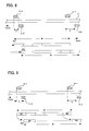
- FIG. 8 is a drawing explaining the amount of position offset between the head in order to explain another position conversion method of this invention.
- FIG. 9 is a drawing explaining position conversion of another embodiment of the invention.
- FIG. 10 is a block diagram of the position control unit of another embodiment of the invention.
- FIG. 11 is a drawing explaining the amount of position offset between heads in order to explain a different position conversion method of the invention.
- FIG. 12 is a drawing explaining position conversion of a different embodiment of the invention.
- FIG. 13 is a block diagram of the position control unit of a different embodiment of the invention.
- FIG. 14 is a flowchart of the position offset measurement for different position conversion of the invention.
- FIG. 15 is a block diagram of the position control unit of yet another embodiment of the invention.
- FIG. 16 is a drawing explaining the table storage area of an embodiment of the invention.
- FIG. 17 is a drawing explaining a disk device of the related art.
- FIG. 18 is a drawing explaining the data area of the related art.
- disk storage device another position control method, and another embodiment.
- FIG. 1 is a schematic diagram of one embodiment of the disk device of this invention
- FIG. 2 is a drawing explaining the actuator in FIG. 1
- FIG. 3 is a drawing explaining the position offset
- FIG. 4 is a schematic diagram of position conversion unit
- FIG. 5 is a drawing explaining position conversion
- FIG. 6 is a drawing explaining the measurement of the starting position
- FIG. 7 is a flowchart of the measurement process.
- FIG. 1 shows an example of using a fixed-type magnetic disk drive as the disk storage device.
- the magnetic disk drive 1 comprises a magnetic disk 2 and a magnetic head 3 .
- the magnetic disk 2 has a plurality of concentric tracks T 0 -T 14000 , and each data track has several sectors in which all of the position information (track number, servo signal) is written. For example, for a 3.5-inch magnetic disk 2 , there are 14,000 tracks on the surface of the disk 1 , and there are 100 sectors on one track.
- the read/write area of this magnetic disk 2 is from track 0 T 0 to track 14 , 000 T 14000 .
- these tracks are written to the magnetic disk 2 by a servo track writer (STW) different from the disk device.
- STW servo track writer
- this magnetic disk 2 is attached to the spindle 4 of the disk drive 1 . Also as shown in FIG. 3, the positions of the heads 23 , 24 of the STW 20 and positions of the heads 3 - 1 , 3 - 2 of the disk device 2 are offset due to the position error between the devices.
- the magnetic head 3 reads information from or writes information to the magnetic disk 2 .
- the magnetic head 3 comprises a MR (GMR, TMR) element, and writing element.
- the magnetic disk 2 is rotated by the spindle motor 4 .
- a rotation-type actuator 5 having a voice-coil motor (VCM) supports the magnetic head 3 as well as moves the magnetic head 3 in the traverse direction across the tracks of the magnetic disk 2 .
- VCM voice-coil motor
- a power amp 6 drives the VCM of the actuator 5 .
- a spindle drive circuit 7 drives the spindle motor 4 .
- a control circuit 8 comprises a microprocessor, digital-signal processor, analog/digital converter, digital/analog converter and RAM 11 .
- the control circuit 8 (called a processor below) reads the position signal from the magnetic head 3 , determines the current position y[k] of the magnetic head, and creates the control amount (control current) u[k] according to the distance (position error) from the target position (physical track position) r.
- a read/write circuit 9 controls reading/writing of the magnetic head 3 .
- a position detection circuit 10 demodulates the servo signal from the magnetic head 3 , and outputs the position signal to the processor 8 .
- a hard-disk controller 12 controls the interface with the host computer.
- RAM 13 in this hard-disk controller 12 .
- the RAM 13 stores data from the host computer and data for the host computer.
- FIG. 2 is a drawing showing the relationship between the aforementioned actuator 5 and the installed magnetic disk 2 .
- the range of motion M of the actuator 5 is regulated by an outer stopper 50 and an inner stopper 51 on the actuator 5 .
- the head 3 - 1 can move in an area M that is smaller than the read area R of the magnetic disk 2 (physical tracks T 0 -T 14000 ).
- the data area M is from physical track 100 to physical track 11 , 000 .
- the starting position of this data area M differs for each actuator and each device. This data area is measured by the measurement described later with FIG. 6 .
- FIG. 4 is a block diagram of the functions of the position control system for doing this, and FIG. 5 is a drawing explaining that process.
- the MCU 8 comprises an interface unit 30 , a position converter 31 and a position control unit 32 .
- the interface unit 30 uses a virtual position table 11 - 1 to convert the logical address from the HDC 12 to a virtual position (head, track).
- the virtual position uses the physical track 0 , for example, as a reference with respect to the physical track of the magnetic disk 2 , and is set within the range of the capacity set for that disk surface such that it is common for each device.
- the position converter 31 uses a correction table 11 - 2 to convert the virtual position to a physical track within the data area.
- the correction table 11 - 2 stores the starting positions Xofs of the data areas for each head 3 - 1 , 3 - 2 as the number of tracks from the physical track 0 of the disk 2 .
- the position converter 31 reads the starting position Xofs from the table 11 - 2 , adds it to the virtual position 31 and calculates the actual physical track. This relationship is shown in FIG. 5, where the starting position is set such that it has a margin, with respect to the position of the outer stopper, for thermal deformation or deformation due to impact.
- the position control unit 32 is a well-known servo control unit that takes the physical track position to be the target position, and calculates the amount of control from the position error between this target position and the current position obtained from the head 3 , and it is possible to use current observer control.
- the table 11 - 2 stores the starting positions for each of the heads 3 - 1 , 3 - 2 .
- the position for each head differs due to installation error. Therefore, since the starting positions for each of the heads differ, the starting position for each head is stored.
- the MCU 8 moves the actuator 5 to the outer side of the disk, and at the point where the actuator will not move any further, the MPU 8 detects the track address that is read by the head. This is performed at the factory and the address is stored in the table 11 - 2 .
- FIG. 6 shows the eccentricity of this disk.
- FIG. 7 is a flowchart of the measurement process for doing this.
- the MCU 8 determines whether the head can move. For example, it determines whether the track number read by the head changes from seeking. When the head has moved, the process returns to step S 3 .
- step S6 the starting sector StartSector is judged whether it is less than the maximum sector MaxSector. When it is less, the process returns to step S 2 .
- a margin for thermal deformation from this measured stopper track position is assumed when setting the starting position, and that value is set in the table 11 - 2 .
- tracks with position information are formed over the enter write area of the disk, and in the case of a disk device that uses this disk, the data area is set according to the range of motion of the device, so even when the starting point of motion of each device differs, it is possible to increase the storage capacity by effectively taking advantage of the range of motion.
- the data area is measured for each device, it is possible to even further increase the storage capacity.
- a hard disk device is explained as the disk device, however, the invention can also be applied to an optical disk device or magneto-optical disk device in which the disk is fixed.
- FIG. 8 and FIG. 9 are drawings explaining another position control method of the invention.
- a rotation-type actuator 5 as shown in FIG. 2, movement in an arc shape. Therefore, the position offset between the two heads 3 - 1 , 3 - 2 on the actuator 5 is different at the outside and inside of the disk 2 as shown in FIG. 8 .
- the position offset between the two heads 3 - 1 , 3 - 2 on the actuator 5 is different at the outside and inside of the disk 2 as shown in FIG. 8 .
- the head 3 - 1 is at track number 1000 and the head 3 - 2 is at track number 1002
- there is an offset of two tracks between the heads there is an offset of two tracks between the heads.
- the head 3 - 1 is at track number 10000 and the head 3 - 2 is at track number 10004 , there is an offset of four tracks between the heads.
- the data area M is divided into a plurality of areas M 1 -Mn according to the difference in position offset between the heads, and a starting point is set for each area.
- the starting point for the outside area of the head 3 - 2 is taken to be track 1002 as is, and the starting point for the inside area becomes track 1004 .
- FIG. 10 is a schematic diagram of a position control unit for another embodiment of the invention, and it is constructed such as to minimize seeking when changing heads.
- the same symbols are used for parts that are identical to those shown in FIG. 4 .
- the correction table 11 - 2 comprises two tables 110 , 111 .
- the first table 110 stores the outside stopper positions for each of the heads 3 - 1 , 3 - 2 .
- the second table 111 stores the amount of position offset of the areas of each of the heads 3 - 1 , 3 - 2 . This position offset is defined as the amount of offset of an area from the outside stopper position.
- the position converter 31 references the table 110 according to the given head number, and finds the outside stopper position for that head, then finds the assigned zone (area) from the virtual track position. Also, the position converter 31 finds the amount of position offset for that zone from table 111 . The converter 31 then adds the external stopper position and the amount of position offset to the virtual position to calculate the physical track position.
- the outside stopper position is obtained from the measurement described above.
- the amount of position offset of each zone is calculated by seeking a specified track that is set for each zone, calculating the amount of position offset between heads from the track number read by each head, and calculating the amount of position offset for each zone of each head. In this case, generally the amount of position offset of the areas of the reference head, head 3 - 1 in FIG. 9, is zero, and the data area of the reference head continues from this.
- the reason for storing the amount of position offset of both heads is, that since the seeking distance is minimized when changing heads, it makes it possible for the reference head to offset in the same way.
- FIG. 11 and FIG. 12 are drawings explaining position conversion of another embodiment of the invention. This is an example of changing the embodiment explained with FIG. 9 and FIG. 10 .
- FIG. 9 and FIG. 10 by setting areas for a plurality of heads and correcting the position offset, it is possible to reduce the amount of seeking when changing heads.
- FIG. 9 and FIG. 10 when the amount of position offset of the reference head is taken to be zero, it is not necessary to store the amount of position offset of the reference head.
- FIG. 13 is a schematic diagram of the position control unit of another embodiment of the invention, and it is constructed to minimize the amount of seeking when changing heads.
- the same symbols are used for parts that are identical to those shown in FIG. 4 and FIG. 10 .
- the correction table 11 - 2 comprises three tables 110 , 111 , 112 .
- the third table 112 stores the physical head numbers which correspond to the virtual heads 0 , 1 that were converted by the interface processing unit 30 .
- the first table 110 stores the outside stopper position for the virtual head 0 .
- the second table 111 takes the areas of the virtual head 0 to be a reference and stores the amount of position offset for each area of the virtual head 1 .
- the position converter 31 references the table 112 according to a given virtual head number, to find the corresponding physical head. Then references the table 110 to find the stopper position for the virtual head number 0 , then finds the assigned zone (area) from the virtual track position. Also, when the virtual head number is ‘1’, the position converter 31 finds the amount of position offset of that zone from table 111 . When the virtual head is ‘0’, the position converter 31 adds the outside stopper position to the virtual track position to calculate the physical track position. Furthermore, when the virtual head is ‘1’, the position converter 31 adds the stopper position and the amount of position offset to the virtual track position to calculate the physical track position.
- the outside stopper position is obtained from the measurement described above.
- the amount of position offset between heads in each zone is obtained by seeking for a specified track set for each zone and calculating the amount of position offset between heads from the track number read by each head. This measurement method is shown in FIG. 14 .
- FIG. 15 is a block diagram of the position control unit of yet another embodiment of the invention.
- the position control unit 32 comprises a computation unit 33 that calculates the position error, and a servo controller 34 .
- the computation unit 33 subtracts the current position, that has been demodulated from the position signal read by the head 3 , from the converted physical track position, and computes the position error.
- the servo controller 34 computes the amount to control the actuator 5 from the position error.
- the servo controller 34 corrects the servo loop gain, corrects the detection sensitivity of the head, and corrects the bias force to be applied to the actuator according to the actuator position.
- the correction processes, using calibration results that are indispensable for positioning control, are performed according to the aforementioned virtual position.
- FIG. 16 is a drawing explaining another embodiment of the invention, and shows the storage position in the aforementioned table 11 - 2 .
- the table 11 - 2 differs for each device, so the storage position becomes a problem.
- One example is storing the positions in non-volatile memory (ROM) on the circuit.
- table 11 - 2 when it becomes necessary to replace the circuit due to some kind of trouble, table 11 - 2 is also lost. Therefore, it takes time to remake the table 11 - 2 for that device. So in order that the table 11 - 2 is not lost from the device when replacing the circuit, the table 11 - 2 is store on disk medium. In this case, the table 11 - 2 , which is unique to the device, can be stored on the center track of the data area (unique information storage area), as shown in FIG. 16 . By doing this, the information can always be accessed even when there is thermal deformation of the disk or the disk receives an impact.
- the position offset for each area is set in the table 11 - 2 such that it is accessed by jumping over the aforementioned area for storing unique information.
- a disk device in which a disk is installed whose entire writing area is formatted with tracks that are written with position information, the data area is set within that area according to the range of motion of the device actuator.
- a logical address from the host is converted to a physical address and the head position is controlled according to this setting. Therefore, in all devices, even when a track-formatted disk has been installed in the device, it is possible to effectively take advantage of the range of motion of the actuator to increase the storage capacity. Moreover, it is possible to make this easier through address conversion.
Abstract
Description
Claims (16)
Applications Claiming Priority (3)
| Application Number | Priority Date | Filing Date | Title |
|---|---|---|---|
| JP2000076785A JP3683157B2 (en) | 2000-03-17 | 2000-03-17 | Head position control method of disk device and disk device |
| JP2000-076785 | 2000-03-17 | ||
| JP2000-76785 | 2000-03-17 |
Publications (2)
| Publication Number | Publication Date |
|---|---|
| US20010022702A1 US20010022702A1 (en) | 2001-09-20 |
| US6819519B2 true US6819519B2 (en) | 2004-11-16 |
Family
ID=18594467
Family Applications (1)
| Application Number | Title | Priority Date | Filing Date |
|---|---|---|---|
| US09/742,585 Expired - Lifetime US6819519B2 (en) | 2000-03-17 | 2000-12-21 | Head position control method for a disk device and the disk device |
Country Status (2)
| Country | Link |
|---|---|
| US (1) | US6819519B2 (en) |
| JP (1) | JP3683157B2 (en) |
Cited By (6)
| Publication number | Priority date | Publication date | Assignee | Title |
|---|---|---|---|---|
| US20040264021A1 (en) * | 2003-06-26 | 2004-12-30 | Lim Teckkhoon | Multi-tracks mr offset tuning based on error count in certification process |
| US20050078402A1 (en) * | 2003-10-14 | 2005-04-14 | Khor Eikfun | Using a mechanical stop for determining an operating parameter of a data handling device |
| US20060114597A1 (en) * | 2004-11-30 | 2006-06-01 | Samsung Electronics Co., Ltd. | Method of compensating for track zero position in reference servo track copying system and disc drive using the same |
| US20060126675A1 (en) * | 2004-12-14 | 2006-06-15 | Kabushiki Kaisha Tocon | Solid-state laser device |
| US20060279870A1 (en) * | 2005-05-26 | 2006-12-14 | Samsung Electronics Co., Ltd. | Method of controlling track seek in HDD and a recording medium therefor |
| US20070070869A1 (en) * | 2005-09-26 | 2007-03-29 | Fujitsu Limited | Magnetic disk apparatus suppressing adjacent track influence |
Families Citing this family (6)
| Publication number | Priority date | Publication date | Assignee | Title |
|---|---|---|---|---|
| JP4156284B2 (en) * | 2002-07-01 | 2008-09-24 | 富士通株式会社 | Head position control method and disk device |
| KR100464438B1 (en) * | 2002-11-25 | 2004-12-31 | 삼성전자주식회사 | Method for heads switching which use mapping of numbers of track |
| DE60232108D1 (en) * | 2002-12-12 | 2009-06-04 | Fujitsu Ltd | Data carrier device, data carrier device assembly, data carrier device manufacturing method |
| JP4612603B2 (en) * | 2006-09-28 | 2011-01-12 | 東芝ストレージデバイス株式会社 | SEEK CONTROL METHOD, SEEK CONTROL DEVICE, AND MEDIUM STORAGE DEVICE |
| CN103714007B (en) * | 2012-09-29 | 2017-02-08 | 联想(北京)有限公司 | Data writing method and electronic equipment |
| JP6759170B2 (en) * | 2017-09-15 | 2020-09-23 | 株式会社東芝 | Hard disk drive and control method |
Citations (11)
| Publication number | Priority date | Publication date | Assignee | Title |
|---|---|---|---|---|
| JPS576414A (en) | 1980-06-11 | 1982-01-13 | Fujitsu Ltd | Evading system for magnetic disk fault |
| JPH04129071A (en) | 1990-09-19 | 1992-04-30 | Fujitsu Ltd | Disk device |
| JPH04172668A (en) | 1990-11-06 | 1992-06-19 | Fujitsu Ltd | Access system to magnetic disk |
| JPH04274002A (en) | 1991-03-01 | 1992-09-30 | Nec Ibaraki Ltd | Magnetic disk controller |
| US5321673A (en) * | 1991-04-12 | 1994-06-14 | Matsushita Electric Industrial Co., Ltd. | Partial ROM type optical disk and its recording and reproducing apparatus |
| US5535372A (en) * | 1994-07-06 | 1996-07-09 | International Business Machines Corporation | Method and apparatus for efficient updating of CKD data stored on fixed block architecture devices |
| US5661848A (en) * | 1994-09-08 | 1997-08-26 | Western Digital Corp | Multi-drive controller with encoder circuitry that generates ECC check bytes using the finite field for optical data for appending to data flowing to HDA |
| US5784220A (en) * | 1994-01-20 | 1998-07-21 | Fujitsu Limited | Magnetic disk apparatus, recording and accessing method for performing density recording |
| US5822142A (en) * | 1996-07-26 | 1998-10-13 | Western Digital Corporation | Method of mapping logical sectors to physical sectors in a disk drive sparing partition |
| US5825728A (en) * | 1992-10-05 | 1998-10-20 | Mitsubishi Denki Kabushiki Kaisha | Optical disk and optical disk drive device |
| US6522497B1 (en) | 1999-12-24 | 2003-02-18 | Kabushiki Kaisha Toshiba | Disk drive having positioning control system using logical cylinder address information |
-
2000
- 2000-03-17 JP JP2000076785A patent/JP3683157B2/en not_active Expired - Fee Related
- 2000-12-21 US US09/742,585 patent/US6819519B2/en not_active Expired - Lifetime
Patent Citations (11)
| Publication number | Priority date | Publication date | Assignee | Title |
|---|---|---|---|---|
| JPS576414A (en) | 1980-06-11 | 1982-01-13 | Fujitsu Ltd | Evading system for magnetic disk fault |
| JPH04129071A (en) | 1990-09-19 | 1992-04-30 | Fujitsu Ltd | Disk device |
| JPH04172668A (en) | 1990-11-06 | 1992-06-19 | Fujitsu Ltd | Access system to magnetic disk |
| JPH04274002A (en) | 1991-03-01 | 1992-09-30 | Nec Ibaraki Ltd | Magnetic disk controller |
| US5321673A (en) * | 1991-04-12 | 1994-06-14 | Matsushita Electric Industrial Co., Ltd. | Partial ROM type optical disk and its recording and reproducing apparatus |
| US5825728A (en) * | 1992-10-05 | 1998-10-20 | Mitsubishi Denki Kabushiki Kaisha | Optical disk and optical disk drive device |
| US5784220A (en) * | 1994-01-20 | 1998-07-21 | Fujitsu Limited | Magnetic disk apparatus, recording and accessing method for performing density recording |
| US5535372A (en) * | 1994-07-06 | 1996-07-09 | International Business Machines Corporation | Method and apparatus for efficient updating of CKD data stored on fixed block architecture devices |
| US5661848A (en) * | 1994-09-08 | 1997-08-26 | Western Digital Corp | Multi-drive controller with encoder circuitry that generates ECC check bytes using the finite field for optical data for appending to data flowing to HDA |
| US5822142A (en) * | 1996-07-26 | 1998-10-13 | Western Digital Corporation | Method of mapping logical sectors to physical sectors in a disk drive sparing partition |
| US6522497B1 (en) | 1999-12-24 | 2003-02-18 | Kabushiki Kaisha Toshiba | Disk drive having positioning control system using logical cylinder address information |
Cited By (11)
| Publication number | Priority date | Publication date | Assignee | Title |
|---|---|---|---|---|
| US20040264021A1 (en) * | 2003-06-26 | 2004-12-30 | Lim Teckkhoon | Multi-tracks mr offset tuning based on error count in certification process |
| US7173781B2 (en) * | 2003-06-26 | 2007-02-06 | Seagate Technology Llc | Multi-tracks MR offset tuning based on error count in certification process |
| US20050078402A1 (en) * | 2003-10-14 | 2005-04-14 | Khor Eikfun | Using a mechanical stop for determining an operating parameter of a data handling device |
| US7397623B2 (en) * | 2003-10-14 | 2008-07-08 | Seagate Technology Llc | Using a mechanical stop for determining an operating parameter of a data handling device |
| US20060114597A1 (en) * | 2004-11-30 | 2006-06-01 | Samsung Electronics Co., Ltd. | Method of compensating for track zero position in reference servo track copying system and disc drive using the same |
| US7663832B2 (en) * | 2004-11-30 | 2010-02-16 | Samsung Electronics Co., Ltd. | Method of compensating for track zero position in reference servo track copying system and disc drive using the same |
| US20060126675A1 (en) * | 2004-12-14 | 2006-06-15 | Kabushiki Kaisha Tocon | Solid-state laser device |
| US20060279870A1 (en) * | 2005-05-26 | 2006-12-14 | Samsung Electronics Co., Ltd. | Method of controlling track seek in HDD and a recording medium therefor |
| US7463445B2 (en) * | 2005-05-26 | 2008-12-09 | Samsung Electronics Co., Ltd. | Method of controlling track seek in HDD and a recording medium therefor |
| US20070070869A1 (en) * | 2005-09-26 | 2007-03-29 | Fujitsu Limited | Magnetic disk apparatus suppressing adjacent track influence |
| US7242550B2 (en) * | 2005-09-26 | 2007-07-10 | Fujitsu Limited | Magnetic disk apparatus suppressing adjacent track influence |
Also Published As
| Publication number | Publication date |
|---|---|
| JP2001266454A (en) | 2001-09-28 |
| US20010022702A1 (en) | 2001-09-20 |
| JP3683157B2 (en) | 2005-08-17 |
Similar Documents
| Publication | Publication Date | Title |
|---|---|---|
| US6650491B2 (en) | System and method for setting a read/write offset and for recovering from data read errors | |
| US7595955B2 (en) | Disk drive device and method for error recovery procedure therefor | |
| US5978168A (en) | MR head differential micro-jog | |
| US7573669B2 (en) | Method and apparatus for writing pattern on disk | |
| US6819519B2 (en) | Head position control method for a disk device and the disk device | |
| KR20080017076A (en) | Head position control method and disk device | |
| US6078460A (en) | Head positioning control system for use in a disk drive | |
| US6456451B1 (en) | Method and apparatus for disk drive seek control | |
| US20090268337A1 (en) | Method and apparatus for determining offset between read head and write head in a disk drive | |
| US5801897A (en) | Head positioning control system for use in a disk storage system | |
| US6160674A (en) | Stable data writing method by tracking head speed in hard disk drive | |
| JP3688874B2 (en) | Disk storage device and head positioning control method | |
| US6646824B1 (en) | Head-positioning control method and device for a disk device | |
| JP4322901B2 (en) | Disk eccentricity measuring method and disk storage device to which the method is applied | |
| US7567406B2 (en) | Method of writing pattern on magnetic disk and device therefor | |
| US20090002872A1 (en) | Method and apparatus for positioning head on data track with a variable track width in a disk drive | |
| JPH0945025A (en) | Disc apparatus and method for measuring shift amount of heads | |
| JP4709797B2 (en) | Head position control method, head position demodulating device, and disk device | |
| US20100238585A1 (en) | Method of controlling flying height of magnetic head of hard disk drive | |
| KR100585164B1 (en) | Method for compensating a track zero position in reference servo track copy system and disc drive using the same | |
| JP4491023B2 (en) | Head position control method, head position control device, and disk device | |
| US5805373A (en) | Head position error compensation in disk drives | |
| JPH0991903A (en) | Apparatus and method for positioning and controlling head of disc-recording/reproducing apparatus | |
| JPH117738A (en) | Disk memory apparatus and method applied to the apparatus for controlling positioning of head | |
| US6956712B2 (en) | Head position demodulating method and disk apparatus |
Legal Events
| Date | Code | Title | Description |
|---|---|---|---|
| AS | Assignment |
Owner name: FUJITSU LIMITED, JAPAN Free format text: ASSIGNMENT OF ASSIGNORS INTEREST;ASSIGNORS:TAKAISHI, KAZUHIKO;KUROBA, YASUMASA;KAMIMURA, MITSUO;AND OTHERS;REEL/FRAME:011419/0177 Effective date: 20001218 |
|
| STCF | Information on status: patent grant |
Free format text: PATENTED CASE |
|
| FEPP | Fee payment procedure |
Free format text: PAYOR NUMBER ASSIGNED (ORIGINAL EVENT CODE: ASPN); ENTITY STATUS OF PATENT OWNER: LARGE ENTITY |
|
| FPAY | Fee payment |
Year of fee payment: 4 |
|
| AS | Assignment |
Owner name: TOSHIBA STORAGE DEVICE CORPORATION, JAPAN Free format text: ASSIGNMENT OF ASSIGNORS INTEREST;ASSIGNOR:FUJITSU LIMITED;REEL/FRAME:023419/0031 Effective date: 20091014 Owner name: TOSHIBA STORAGE DEVICE CORPORATION, JAPAN Free format text: ASSIGNMENT OF ASSIGNORS INTEREST;ASSIGNOR:FUJITSU LIMITED;REEL/FRAME:023861/0881 Effective date: 20091014 Owner name: TOSHIBA STORAGE DEVICE CORPORATION,JAPAN Free format text: ASSIGNMENT OF ASSIGNORS INTEREST;ASSIGNOR:FUJITSU LIMITED;REEL/FRAME:023861/0881 Effective date: 20091014 |
|
| XAS | Not any more in us assignment database |
Free format text: ASSIGNMENT OF ASSIGNORS INTEREST;ASSIGNOR:FUJITSU LIMITED;REEL/FRAME:023419/0031 |
|
| AS | Assignment |
Owner name: KABUSHIKI KAISHA TOSHIBA, JAPAN Free format text: ASSIGNMENT OF ASSIGNORS INTEREST;ASSIGNOR:TOSHIBA STORAGE DEVICE CORPORATION;REEL/FRAME:027590/0695 Effective date: 20120113 |
|
| FPAY | Fee payment |
Year of fee payment: 8 |
|
| FPAY | Fee payment |
Year of fee payment: 12 |