US6768279B1 - Reprogrammable motor drive and control therefore - Google Patents
Reprogrammable motor drive and control therefore Download PDFInfo
- Publication number
- US6768279B1 US6768279B1 US08/250,286 US25028694A US6768279B1 US 6768279 B1 US6768279 B1 US 6768279B1 US 25028694 A US25028694 A US 25028694A US 6768279 B1 US6768279 B1 US 6768279B1
- Authority
- US
- United States
- Prior art keywords
- motor
- appliance
- versions
- given appliance
- memory
- Prior art date
- Legal status (The legal status is an assumption and is not a legal conclusion. Google has not performed a legal analysis and makes no representation as to the accuracy of the status listed.)
- Active, expires
Links
Images

Classifications
-
- H—ELECTRICITY
- H02—GENERATION; CONVERSION OR DISTRIBUTION OF ELECTRIC POWER
- H02P—CONTROL OR REGULATION OF ELECTRIC MOTORS, ELECTRIC GENERATORS OR DYNAMO-ELECTRIC CONVERTERS; CONTROLLING TRANSFORMERS, REACTORS OR CHOKE COILS
- H02P23/00—Arrangements or methods for the control of AC motors characterised by a control method other than vector control
- H02P23/0077—Characterised by the use of a particular software algorithm
-
- H—ELECTRICITY
- H02—GENERATION; CONVERSION OR DISTRIBUTION OF ELECTRIC POWER
- H02P—CONTROL OR REGULATION OF ELECTRIC MOTORS, ELECTRIC GENERATORS OR DYNAMO-ELECTRIC CONVERTERS; CONTROLLING TRANSFORMERS, REACTORS OR CHOKE COILS
- H02P7/00—Arrangements for regulating or controlling the speed or torque of electric DC motors
-
- H—ELECTRICITY
- H02—GENERATION; CONVERSION OR DISTRIBUTION OF ELECTRIC POWER
- H02P—CONTROL OR REGULATION OF ELECTRIC MOTORS, ELECTRIC GENERATORS OR DYNAMO-ELECTRIC CONVERTERS; CONTROLLING TRANSFORMERS, REACTORS OR CHOKE COILS
- H02P25/00—Arrangements or methods for the control of AC motors characterised by the kind of AC motor or by structural details
- H02P25/02—Arrangements or methods for the control of AC motors characterised by the kind of AC motor or by structural details characterised by the kind of motor
- H02P25/08—Reluctance motors
-
- H—ELECTRICITY
- H02—GENERATION; CONVERSION OR DISTRIBUTION OF ELECTRIC POWER
- H02P—CONTROL OR REGULATION OF ELECTRIC MOTORS, ELECTRIC GENERATORS OR DYNAMO-ELECTRIC CONVERTERS; CONTROLLING TRANSFORMERS, REACTORS OR CHOKE COILS
- H02P6/00—Arrangements for controlling synchronous motors or other dynamo-electric motors using electronic commutation dependent on the rotor position; Electronic commutators therefor
- H02P6/34—Modelling or simulation for control purposes
Definitions
- This invention relates to dynamoelectric machines in the form of electric motors, and more particularly, to a simple, effective way of controlling operation of a motor when used by different manufacturers for different purposes. While the invention is described in particular detail with respect to its application in appliances, those skilled in the art will recognize the wider applicability of the inventive principles described hereinafter.
- electric motors are designed so that a particular motor has a different set of operating characteristics for one application, and another set of operating characteristics for other applications.
- motors were designed and tested with respect to a specific application until the operating criteria met desired goals.
- HVAC heating and air conditioning systems
- the motor design can vary depending upon a number of anticipated load characteristics.
- the load characteristics are a function of a number of variables, including the type of air handler used with a motor, and can vary from one manufacturer to another.
- the problem is further complicated because of the variety of electric motor “types” available for use in HVAC applications. For example, induction motors long have been the predominant choice in blower applications. More recently, brushless permanent magnet, switched reluctance, controlled induction, and similar electronically operated motors have found use in such applications.
- the OEM manufacturer also incurs increased costs because the OEM must stock and track a variety of motors for its various product lines.
- a motor manufacturer can reduce costs if the manufacturer had the ability to produce one version of a motor for a particular application, the motor being readily adapted after manufacture, for each different OEM's particular set of operating requirements. It also is advantageous to enable a particular motor to be used across a range of models for a particular OEM, based on function and performance of any particular model. Another advantage of our invention is that the OEM manufacturer is able to supply motors to fit new applications more quickly.
- One of the objects of this invention is to provide a drive apparatus for a dynamoelectric machine.
- Another object of this invention is to provide a drive apparatus for a dynamoelectric machine which enables essentially the same dynamoelectric machine construction to be used in a variety of versions of an appliance.
- Another object of this invention is to provide a drive apparatus which is adaptable after manufacture to a variety of usages.
- Another object of this invention is to provide a motor drive incorporating a microcontroller which has a set of parameters or an operating program sequence for the motor stored in it, a second memory having a series of data stored in association with it, and switches operatively connected to the microcontroller to enable the microcontroller to select the appropriate data for operation of the motor.
- Another object of this invention is to provide a drive means with an associated motor capable of use over both a wide range of manufacturers and over a range of products of a single manufacturer.
- Another object of this invention is to provide a drive which is designed to operate an electric motor satisfactorily under a wide range of selectable conditions.
- Another object of this invention is to provide a drive apparatus which reduces inventory control problems for both the motor manufacturer and the original equipment manufacturer.
- Another object of this invention is to provide a motor drive which is low in cost and which is readily associated with the motor structure.
- Still another object of the invention is to provide a motor and motor drive in which operative characteristics of the motor can be changed without the use of special tools or equipment.
- a drive apparatus for use with an electric motor having a low cost microcontroller adapted to operate a motor drive.
- the motor drive is operatively connected to the electric motor to control at least one of the current or voltage of the motor.
- the microcontroller supplies control information to the drive.
- the microcontroller includes a program module in the form of a ROM for controlling motor operation.
- a second and nonvolatile memory module in the form of an EEPROM is provided for storing motor operating characteristic information, the information being accessible by the microcontroller.
- Multi-position switches are connected to the processor module.
- the data in the second memory module determines the function of the switches. Data in the second memory module also determines the operating condition (values, parameters) of the drive apparatus.
- a separate programming device is used to download data to the microcontroller and to the second memory module.
- a plurality of switches are selectable by an installer of the motor, and the switch settings determine which functions the program module executes and how the program module uses the data stored in the second memory module.
- one motor design may be used for one set of operating characteristics of the motor, while a second set of operating conditions may be obtained merely by changing the switch settings.
- data may later be loaded to the nonvolatile memory which alters the information selectable by the switches and the program flow thereby alters the operating characteristics of the motor.
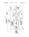
- FIG. 1 is a block diagram of one illustrated embodiment of drive apparatus of the present invention
- FIG. 2 is a view of selection switches used in conjunction with the drive apparatus of FIG. 1 to select motor operational data
- FIG. 3 is a block diagram of a memory containing operating characteristics associated with different versions of an appliance.
- appliance A may be any of a variety of conventionally available devices taking the form, for example, of furnace blowers, compressor motors, washing machines, dryers, and other similar related applications.
- the motor M also is intended to be any of a variety of known constructions.
- the motor may be a brushless permanent magnet, switched reluctance motor or controlled induction motor. Each of these motor types differ primarily in the construction of their rotors.
- the controlled induction motor employs what is known in the art as a squirrel cage induction motor rotor, while a switched reluctance motor employs an iron core rotor which may have a special configuration but is constructed without the rotor bars of the squirrel cage design.
- the brushless permanent magnet motor has permanent magnets associated with the rotor.
- the stator assemblies of any of the motors generally are conventional designs, although the windings of the stator assembly often are specifically designed to enhance the performance characteristics of each of the motor types.
- a drive apparatus 10 of the present invention allows a motor manufacturer to make a single model of a motor M, but still enables an OEM to tailor the drive apparatus to a variety of applicational uses.
- the apparatus 10 further allows each OEM to install the motor M in a product having a set of operating characteristics unique to that manufacturer. Thereafter, the drive apparatus 10 may be adjusted to provide proper operating performance in the particular application.
- Apparatus 10 includes a drive means 12 operatively associated with the motor M.
- the drive means 12 is, in the preferred embodiment, a conventional inverter bridge circuit operatively connected to the stator assembly of motor M.
- the inverter bridge operates to control at least one of the current or voltage of motor M.
- the drive means 12 includes a plurality of power switching devices S, as represented by power transistors, for example, for controlling current flow through the motor phase windings (not shown).
- the drive means 12 controls the motor so that it operates at any one of a particularly selected condition. The selected condition depends on a variety of application characteristics, as described in greater detail hereinafter.
- the drive means 12 is responsive to control inputs provided to it to vary at least the current or the voltage input to the motor M.
- the drive means provides information concerning the instantaneous operating conditions of the motor to a microcontroller 14 through a suitable interface 40 .
- a processing means 13 of apparatus 10 supplies motor control information to drive means 12 .
- Processing means 13 includes the microcontroller 14 .
- the microcontroller 14 has a first memory means associated with it in the form of a read only memory (ROM) module 16 .
- Module 16 includes a fixed program which is inscribed in it during its manufacture. The program allows microcontroller 14 to control operation of motor M under various appliance operating conditions.
- the microcontroller 14 also has associated with it a second nonvolatile memory means in the form of an electrically erasable programmable read only memory (EEPROM) 18 .
- the memory module 18 has data stored in it used to control operation of motor M.
- EEPROM 18 is a nonvolatile memory, so that motor operating characteristic information stored therein is not lost when power is removed from the apparatus A. While EEPROM 18 is shown as a separate block in FIG. 1, those skilled in the art will recognize that a single integrated circuit may include what is shown separately in the drawings as microcontroller 14 , ROM 16 and EEPROM 18
- Microcontroller 14 has an input 30 .
- the input 30 preferably is connected to an external device through an opto-coupler 31 .
- Microcontroller 14 also has a plurality of switches 20 , operatively connected to it through input lines or ports.
- the switches are manually operable multi-position switches SW 1 -SWN.
- the switches are shown as eight position manually operable rotary switches in FIG. 2 . It will be understood, however, that the switches may have any reasonable number of switch positions. Also, the various switches need not have the same number of positions as each of the other switches; and, various other types of switch constructions are compatible with the broader aspects of our invention. For the three, eight position switches SW 1 -SW 3 shown in FIG. 2, there are 512 (8 ⁇ 8 ⁇ 8) possible switch settings which an installer or user of the motor can select.
- a programming device 22 which can be a general purpose computer or a special use device, for example, is operatively connected through the opto-coupler 31 to the input 30 of the microcontroller 14 .
- the programmer 22 is utilized to download appropriate data through the microcontroller to the EEPROM 18 .
- the programmer 22 allows the motor manufacturer or OEM both to download appropriate information at the time of manufacture, and to update that information at a later time. If, for example, a new application is found for the motor, information relevant to that use can be loaded into the memory 18 as each new unit is constructed. Fabrication of a new memory chip is not required. Similarly, if previous motor operating data is refined, the memory in existing units is readily updated without having to recall or retrofit existing units.
- the programmer 22 is removably connected to drive apparatus 10 .
- a system master control may be connected to the input 30 .
- a thermostat and thermostat wires may be connected to the blower motor control.
- Such wires would, with our invention, instead be connected to the microcontroller 14 through suitable input means.
- the switches 20 are used to select relevant portions of the data contained in the memories 16 and 18 .
- the switch position may represent fan blower constants employed in the control algorithm for an HVAC system.
- the start delay for application for the furnace blower i.e., the time between the energization of the heat element of the furnace, for example, and blower start up also can be indicated by switch position.
- the stop delay that is, the time between de-energization of a heating element, for example, and motor speed reduction, because of the heater turn-off, also may be selected by a switch position.
- Various commands representing desired air flow also can be represented by the switch positions. As will be appreciated by those skilled in the art, individual ones of the switch positions need not affect the variable selected by another of the switch positions. Thus, our invention allows considerable variation in function selections in determining system operation.
- the microcontroller 14 reads switch 20 and the information set by the switches to obtain data for motor M operation.
- the microcontroller 14 also reads the commands from a system master controller 35 , and utilizing the information available from the system master controller and the switches, accesses the data in the memory 18 to operate motor M.
- the ability to use the switch readings to access data in the memories 16 and 18 , in which the data in memory 18 may be altered after apparatus construction, is an important feature of our invention in that it enables a motor manufacturer to use a single motor model in a wide variety of applicational uses merely by altering the switch position of the switches 20 .
- the use of the switches 20 enables one user of the motor M to select one set of operating characteristics for the motor by making one switch setting, while a second user can, by altering the switch selection position, enable the microcontroller 14 to access other operating data information in the memories 16 and 18 .
- the apparatus, and the electric motor M applied to the apparatus is usable in different versions of the same appliance, and enables the appliance manufacturer to offer a unique set of operating characteristics for each such use.
- FIG. 3 shows the memory 18 having operating characteristics 42 therein associated with versions 1 -n of an appliance.
- control of this invention to read the switch 20 position and associated that position with data downloadable to a nonvolatile memory enables motors produced in accordance with this invention to offer a range of programmability and functionality not heretofore associated with motor designs. This result is achieved at a relatively low cost.
- the apparatus may be packaged with the motor itself, or may form a separate unit operatively connected to the motor in application use.
- the various memories associated with the microcontroller 14 may be incorporated in an integrated design, or the memories may be separate units associated with the microcontroller 14 in a conventional manner. Other memory devices may be employed. While preferably the program for operation of the microcontroller was described as being loaded during ROM manufacture, both the program and data for that program may be downloaded by the programmer in other embodiments of the invention. These variations are merely illustrative.
Abstract
Description
Claims (4)
Priority Applications (7)
| Application Number | Priority Date | Filing Date | Title |
|---|---|---|---|
| US08/250,286 US6768279B1 (en) | 1994-05-27 | 1994-05-27 | Reprogrammable motor drive and control therefore |
| CA002148633A CA2148633C (en) | 1994-05-27 | 1995-05-04 | Motor drive with programmable function switches |
| EP95630050A EP0684692A3 (en) | 1994-05-27 | 1995-05-19 | Motor drive with programmable funtion switches. |
| BR9502547A BR9502547A (en) | 1994-05-27 | 1995-05-25 | Drive device for use with electrodynamic machine and electrodynamic machine operation control process |
| JP7151096A JPH0866083A (en) | 1994-05-27 | 1995-05-25 | Driver for dynamoelectric apparatus |
| KR1019950013542A KR950035038A (en) | 1994-05-27 | 1995-05-27 | Motor-drive unit and method with programmable function switch |
| TW087218509U TW412111U (en) | 1994-05-27 | 1995-06-13 | Drive apparatus for use with a dynamoelectric machine and an electric motor and drive apparatus for controlling a dynamoelectric machine |
Applications Claiming Priority (1)
| Application Number | Priority Date | Filing Date | Title |
|---|---|---|---|
| US08/250,286 US6768279B1 (en) | 1994-05-27 | 1994-05-27 | Reprogrammable motor drive and control therefore |
Publications (1)
| Publication Number | Publication Date |
|---|---|
| US6768279B1 true US6768279B1 (en) | 2004-07-27 |
Family
ID=22947124
Family Applications (1)
| Application Number | Title | Priority Date | Filing Date |
|---|---|---|---|
| US08/250,286 Active 2026-05-30 US6768279B1 (en) | 1994-05-27 | 1994-05-27 | Reprogrammable motor drive and control therefore |
Country Status (7)
| Country | Link |
|---|---|
| US (1) | US6768279B1 (en) |
| EP (1) | EP0684692A3 (en) |
| JP (1) | JPH0866083A (en) |
| KR (1) | KR950035038A (en) |
| BR (1) | BR9502547A (en) |
| CA (1) | CA2148633C (en) |
| TW (1) | TW412111U (en) |
Cited By (48)
| Publication number | Priority date | Publication date | Assignee | Title |
|---|---|---|---|---|
| US20040172986A1 (en) * | 2002-04-17 | 2004-09-09 | Heo Seong Eun | Washer |
| US20050116570A1 (en) * | 2000-11-15 | 2005-06-02 | Edelson Jonathan S. | Mesh connected electrical rotating machine with span changing |
| US6968842B1 (en) * | 2002-04-03 | 2005-11-29 | Ric Investments, Inc. | Measurement of a fluid parameter in a pressure support system |
| US20060273686A1 (en) * | 2004-06-21 | 2006-12-07 | Edelson Jonathan S | Hub motors |
| US20070120518A1 (en) * | 2003-12-18 | 2007-05-31 | Rosoli Jean M | Electric motor controller for a domestic appliance |
| US20070124847A1 (en) * | 2005-12-05 | 2007-06-07 | Seongjun Yoon | Hand-packing instrument in the form of gloves |
| US7230400B1 (en) * | 1998-10-05 | 2007-06-12 | Ebm-Papst St. Georgen Gmbh & Co. Kg | Electronically commutated motor |
| US20070205732A1 (en) * | 2006-03-01 | 2007-09-06 | Regal-Beloit Corporation | Methods and systems for emulating an induction motor utilizing an electronically commutated motor |
| US20080007070A1 (en) * | 2000-11-15 | 2008-01-10 | Edelson Jonathan S | Chimney turbine |
| US20080042507A1 (en) * | 2000-11-15 | 2008-02-21 | Edelson Jonathan S | Turbine starter-generator |
| US20080095639A1 (en) * | 2006-10-13 | 2008-04-24 | A.O. Smith Corporation | Controller for a motor and a method of controlling the motor |
| US20080095638A1 (en) * | 2006-10-13 | 2008-04-24 | A.O. Smith Corporation | Controller for a motor and a method of controlling the motor |
| US7375483B2 (en) | 2000-10-23 | 2008-05-20 | Borealis Technical Limited | Mesh connected brake array for electrical rotating machines |
| US20080129137A1 (en) * | 1993-01-22 | 2008-06-05 | Jonathan Sidney Edelson | Motor Winding |
| US20080147252A1 (en) * | 2005-03-01 | 2008-06-19 | Janice Ilene Bayer | Motor Controller |
| US20080218112A1 (en) * | 2007-03-09 | 2008-09-11 | Beifus Brian L | Methods and systems for recording operating information of an electronically commutated motor |
| US20090128067A1 (en) * | 2006-08-01 | 2009-05-21 | Paul Steven Mullin | Interface cord and system including an interface cord |
| US20090290989A1 (en) * | 2004-04-09 | 2009-11-26 | William Louis Mehlhorn | Controller for a motor and a method of controlling the motor |
| US20090300270A1 (en) * | 2008-05-29 | 2009-12-03 | Shahi Prakash B | Dynamoelectric machine assemblies having memory for use by external devices |
| US20090302787A1 (en) * | 2005-04-19 | 2009-12-10 | Jonathan Sidney Edelson | Induction and switched reluctance motor |
| US20100080714A1 (en) * | 2008-10-01 | 2010-04-01 | A. O. Smith Corporation | Controller for a motor and a method of controlling the motor |
| US20100219788A1 (en) * | 2000-10-23 | 2010-09-02 | Borealis Technical Limited | High phase order AC Machine with Short Pitch Winding |
| US20110167879A1 (en) * | 2008-05-02 | 2011-07-14 | Arcelik Anonim Sirketi | Washing Machine |
| US20110254477A1 (en) * | 2010-04-19 | 2011-10-20 | Emerson Electric Co. | Blower motor for hvac systems |
| US8133034B2 (en) | 2004-04-09 | 2012-03-13 | Regal Beloit Epc Inc. | Controller for a motor and a method of controlling the motor |
| US20120158267A1 (en) * | 2010-01-15 | 2012-06-21 | Toyota Jidosha Kabushiki Kaisha | Valve working angle variable system |
| US8281425B2 (en) | 2004-11-01 | 2012-10-09 | Cohen Joseph D | Load sensor safety vacuum release system |
| US8360736B2 (en) | 2006-10-13 | 2013-01-29 | Regal Beloit Epc Inc. | Controller for a motor and a method of controlling the motor |
| US20130234630A1 (en) * | 2010-11-10 | 2013-09-12 | Wellingtion Drive Technologies Limited | Programmable motor and method |
| US8579908B2 (en) | 2003-09-26 | 2013-11-12 | DePuy Synthes Products, LLC. | Device for delivering viscous material |
| US20150104311A1 (en) * | 2013-10-10 | 2015-04-16 | Gentherm Automotive Systems (China) Ltd. | Externally programmable fan |
| US20150120014A1 (en) * | 2013-10-29 | 2015-04-30 | Kabushiki Kaisha Yaskawa Denki | Industrial equipment production system, industrial equipment production server, industrial equipment production method, and information storage medium |
| US9328727B2 (en) | 2003-12-08 | 2016-05-03 | Pentair Water Pool And Spa, Inc. | Pump controller system and method |
| US9404500B2 (en) | 2004-08-26 | 2016-08-02 | Pentair Water Pool And Spa, Inc. | Control algorithm of variable speed pumping system |
| US9438159B2 (en) * | 2014-06-26 | 2016-09-06 | Nidec Motor Corporation | System and method for detecting and controlling a motor |
| US9551344B2 (en) | 2004-08-26 | 2017-01-24 | Pentair Water Pool And Spa, Inc. | Anti-entrapment and anti-dead head function |
| US9556874B2 (en) | 2009-06-09 | 2017-01-31 | Pentair Flow Technologies, Llc | Method of controlling a pump and motor |
| US9568005B2 (en) | 2010-12-08 | 2017-02-14 | Pentair Water Pool And Spa, Inc. | Discharge vacuum relief valve for safety vacuum release system |
| US9726184B2 (en) | 2008-10-06 | 2017-08-08 | Pentair Water Pool And Spa, Inc. | Safety vacuum release system |
| US9777733B2 (en) | 2004-08-26 | 2017-10-03 | Pentair Water Pool And Spa, Inc. | Flow control |
| US9885360B2 (en) | 2012-10-25 | 2018-02-06 | Pentair Flow Technologies, Llc | Battery backup sump pump systems and methods |
| US9932984B2 (en) | 2004-08-26 | 2018-04-03 | Pentair Water Pool And Spa, Inc. | Pumping system with power optimization |
| US10240604B2 (en) | 2004-08-26 | 2019-03-26 | Pentair Water Pool And Spa, Inc. | Pumping system with housing and user interface |
| US10465676B2 (en) | 2011-11-01 | 2019-11-05 | Pentair Water Pool And Spa, Inc. | Flow locking system and method |
| US10731655B2 (en) | 2004-08-26 | 2020-08-04 | Pentair Water Pool And Spa, Inc. | Priming protection |
| US10871001B2 (en) | 2004-08-26 | 2020-12-22 | Pentair Water Pool And Spa, Inc. | Filter loading |
| US10947981B2 (en) | 2004-08-26 | 2021-03-16 | Pentair Water Pool And Spa, Inc. | Variable speed pumping system and method |
| US11431176B2 (en) | 2014-09-30 | 2022-08-30 | The Boeing Company | Parallel modular converter architecture |
Families Citing this family (13)
| Publication number | Priority date | Publication date | Assignee | Title |
|---|---|---|---|---|
| WO1998019389A1 (en) | 1996-10-31 | 1998-05-07 | Ebara Corporation | Rotating machine integrated with controller, and inverter |
| IT1298550B1 (en) | 1998-02-04 | 2000-01-12 | Whirlpool Co | CONTROL DEVICE OF A HOUSEHOLD APPLIANCE WITH NON-VOLATILE MEMORY EASILY RE-PROGRAMMABLE FROM THE OUTSIDE |
| FI116338B (en) * | 1998-07-23 | 2005-10-31 | Abb Oy | Arrangement and method in an electrical machine |
| DE19836882A1 (en) * | 1998-08-14 | 2000-02-17 | Papst Motoren Gmbh & Co Kg | Electric motor has characteristic field stored as digital values for associating parameter and motor speed values, and microcontroller or microprocessor |
| IT1304664B1 (en) * | 1998-09-30 | 2001-03-28 | Merloni Elettrodomestici Spa | SYSTEM FOR THE PROGRAMMING OF A HOUSEHOLD APPLIANCE ELECTRONIC CONTROL. |
| US6356044B1 (en) | 1999-12-03 | 2002-03-12 | General Electric Company | Motor with programming module |
| KR100448720B1 (en) * | 2002-05-07 | 2004-09-13 | (주)한국비이피 | Eddy Current Exciter Controller |
| US7102303B2 (en) | 2003-04-30 | 2006-09-05 | Black & Decker Inc. | Generic motor control system and method |
| US7646155B2 (en) | 2003-04-30 | 2010-01-12 | Balck & Decker Inc. | Generic motor control system |
| ES2238155B1 (en) * | 2003-10-07 | 2006-11-01 | Appliances Components Companies Spain, S.A. | COMPRESSOR CONTROL UNIT. |
| WO2006048471A1 (en) * | 2004-10-26 | 2006-05-11 | Appliances Components Companies Spain, S.A. | Compressor control unit |
| DE102007058880A1 (en) * | 2007-12-05 | 2009-06-10 | Sew-Eurodrive Gmbh & Co. Kg | Electric device, electronic motor and inverter motor |
| IT1400846B1 (en) * | 2010-07-07 | 2013-07-02 | Indesit Co Spa | METHOD OF SELECTION OF A SET OF PARAMETERS FOR THE OPERATION OF AN ELECTRIC MOTOR USED IN A WASHING AND / OR DRYING MACHINE AND AN IMPLEMENTING WASHING AND / OR DRYING MACHINE. |
Citations (14)
| Publication number | Priority date | Publication date | Assignee | Title |
|---|---|---|---|---|
| US3176207A (en) | 1961-06-19 | 1965-03-30 | Emerson Electric Co | Electrical motor drive system having position control |
| US4477874A (en) * | 1980-11-25 | 1984-10-16 | Nippondenso Co., Ltd. | Card-operated control system for vehicle components |
| US4659145A (en) * | 1982-03-15 | 1987-04-21 | Hans Obersteiner | Adjustable vehicle seat |
| US4683411A (en) * | 1984-09-21 | 1987-07-28 | General Electric Company | Synchronous motor protection |
| US4686437A (en) * | 1980-06-20 | 1987-08-11 | Kollmorgen Technologies Corporation | Electromechanical energy conversion system |
| US4743815A (en) | 1987-09-01 | 1988-05-10 | Emerson Electric Co. | Brushless permanent magnet motor system |
| US4986092A (en) | 1989-04-12 | 1991-01-22 | Emerson Electric Co. | Speed control for inverter driven washing machine |
| US5023528A (en) * | 1988-10-27 | 1991-06-11 | Advanced Engineering Systems, Operation & Products, Inc. | Method of three-phase winding motor control of rotary motor-driven linear actuators, linear motor-actuated carriages, and similar systems, and apparatus for practicing the same |
| US5115181A (en) | 1990-10-05 | 1992-05-19 | Emerson Electric Co. | Power converter for a switched reluctance motor |
| USRE34286E (en) * | 1987-12-15 | 1993-06-22 | Hitachi, Ltd. | Method and apparatus for operating vacuum cleaner |
| US5235504A (en) | 1991-03-15 | 1993-08-10 | Emerson Electric Co. | High power-factor converter for motor drives and power supplies |
| US5241257A (en) | 1989-04-17 | 1993-08-31 | Emerson Electric Co. | Drive system for household appliances |
| US5276939A (en) * | 1991-02-14 | 1994-01-11 | Sanyo Electric Co., Ltd. | Electric vacuum cleaner with suction power responsive to nozzle conditions |
| US5294872A (en) * | 1986-10-08 | 1994-03-15 | Hitachi, Ltd. | Method and apparatus for operating vacuum cleaner |
Family Cites Families (3)
| Publication number | Priority date | Publication date | Assignee | Title |
|---|---|---|---|---|
| JPS5932812A (en) * | 1982-08-18 | 1984-02-22 | Sony Tektronix Corp | Controlling method of preset value |
| JPS61150686A (en) * | 1984-12-25 | 1986-07-09 | Fanuc Ltd | Servo motor control system |
| US5592058A (en) * | 1992-05-27 | 1997-01-07 | General Electric Company | Control system and methods for a multiparameter electronically commutated motor |
-
1994
- 1994-05-27 US US08/250,286 patent/US6768279B1/en active Active
-
1995
- 1995-05-04 CA CA002148633A patent/CA2148633C/en not_active Expired - Fee Related
- 1995-05-19 EP EP95630050A patent/EP0684692A3/en not_active Ceased
- 1995-05-25 JP JP7151096A patent/JPH0866083A/en active Pending
- 1995-05-25 BR BR9502547A patent/BR9502547A/en not_active Application Discontinuation
- 1995-05-27 KR KR1019950013542A patent/KR950035038A/en not_active Application Discontinuation
- 1995-06-13 TW TW087218509U patent/TW412111U/en unknown
Patent Citations (14)
| Publication number | Priority date | Publication date | Assignee | Title |
|---|---|---|---|---|
| US3176207A (en) | 1961-06-19 | 1965-03-30 | Emerson Electric Co | Electrical motor drive system having position control |
| US4686437A (en) * | 1980-06-20 | 1987-08-11 | Kollmorgen Technologies Corporation | Electromechanical energy conversion system |
| US4477874A (en) * | 1980-11-25 | 1984-10-16 | Nippondenso Co., Ltd. | Card-operated control system for vehicle components |
| US4659145A (en) * | 1982-03-15 | 1987-04-21 | Hans Obersteiner | Adjustable vehicle seat |
| US4683411A (en) * | 1984-09-21 | 1987-07-28 | General Electric Company | Synchronous motor protection |
| US5294872A (en) * | 1986-10-08 | 1994-03-15 | Hitachi, Ltd. | Method and apparatus for operating vacuum cleaner |
| US4743815A (en) | 1987-09-01 | 1988-05-10 | Emerson Electric Co. | Brushless permanent magnet motor system |
| USRE34286E (en) * | 1987-12-15 | 1993-06-22 | Hitachi, Ltd. | Method and apparatus for operating vacuum cleaner |
| US5023528A (en) * | 1988-10-27 | 1991-06-11 | Advanced Engineering Systems, Operation & Products, Inc. | Method of three-phase winding motor control of rotary motor-driven linear actuators, linear motor-actuated carriages, and similar systems, and apparatus for practicing the same |
| US4986092A (en) | 1989-04-12 | 1991-01-22 | Emerson Electric Co. | Speed control for inverter driven washing machine |
| US5241257A (en) | 1989-04-17 | 1993-08-31 | Emerson Electric Co. | Drive system for household appliances |
| US5115181A (en) | 1990-10-05 | 1992-05-19 | Emerson Electric Co. | Power converter for a switched reluctance motor |
| US5276939A (en) * | 1991-02-14 | 1994-01-11 | Sanyo Electric Co., Ltd. | Electric vacuum cleaner with suction power responsive to nozzle conditions |
| US5235504A (en) | 1991-03-15 | 1993-08-10 | Emerson Electric Co. | High power-factor converter for motor drives and power supplies |
Cited By (116)
| Publication number | Priority date | Publication date | Assignee | Title |
|---|---|---|---|---|
| US8258665B2 (en) | 1993-01-22 | 2012-09-04 | Borealis Technical Limited | Motor winding |
| US20080129137A1 (en) * | 1993-01-22 | 2008-06-05 | Jonathan Sidney Edelson | Motor Winding |
| US7230400B1 (en) * | 1998-10-05 | 2007-06-12 | Ebm-Papst St. Georgen Gmbh & Co. Kg | Electronically commutated motor |
| US7928683B2 (en) | 2000-10-23 | 2011-04-19 | Borealis Technical Limited | High phase order AC machine with short pitch winding |
| US20100219788A1 (en) * | 2000-10-23 | 2010-09-02 | Borealis Technical Limited | High phase order AC Machine with Short Pitch Winding |
| US7375483B2 (en) | 2000-10-23 | 2008-05-20 | Borealis Technical Limited | Mesh connected brake array for electrical rotating machines |
| US7327105B2 (en) | 2000-11-15 | 2008-02-05 | Borealis Technical Limited | Mesh connected electrical rotating machine with span changing |
| US8198746B2 (en) | 2000-11-15 | 2012-06-12 | Borealis Technical Limited | Chimney turbine |
| US20080007070A1 (en) * | 2000-11-15 | 2008-01-10 | Edelson Jonathan S | Chimney turbine |
| US7116019B2 (en) * | 2000-11-15 | 2006-10-03 | Borealis Technical Limited | Mesh connected electrical rotating machine with span changing |
| US20080042507A1 (en) * | 2000-11-15 | 2008-02-21 | Edelson Jonathan S | Turbine starter-generator |
| US20070013238A1 (en) * | 2000-11-15 | 2007-01-18 | Edelson Jonathan S | Mesh connected electrical rotating machine with span changing |
| US20050116570A1 (en) * | 2000-11-15 | 2005-06-02 | Edelson Jonathan S. | Mesh connected electrical rotating machine with span changing |
| US7588031B2 (en) | 2002-04-03 | 2009-09-15 | Ric Investments, Llc | Measurement of a fluid parameter in a pressure support system |
| US6968842B1 (en) * | 2002-04-03 | 2005-11-29 | Ric Investments, Inc. | Measurement of a fluid parameter in a pressure support system |
| US7418838B2 (en) * | 2002-04-17 | 2008-09-02 | Lg Electronics Inc. | Washer |
| US20040172986A1 (en) * | 2002-04-17 | 2004-09-09 | Heo Seong Eun | Washer |
| US8579908B2 (en) | 2003-09-26 | 2013-11-12 | DePuy Synthes Products, LLC. | Device for delivering viscous material |
| US10111697B2 (en) | 2003-09-26 | 2018-10-30 | DePuy Synthes Products, Inc. | Device for delivering viscous material |
| US10289129B2 (en) | 2003-12-08 | 2019-05-14 | Pentair Water Pool And Spa, Inc. | Pump controller system and method |
| US9399992B2 (en) | 2003-12-08 | 2016-07-26 | Pentair Water Pool And Spa, Inc. | Pump controller system and method |
| US9371829B2 (en) | 2003-12-08 | 2016-06-21 | Pentair Water Pool And Spa, Inc. | Pump controller system and method |
| US9328727B2 (en) | 2003-12-08 | 2016-05-03 | Pentair Water Pool And Spa, Inc. | Pump controller system and method |
| US10241524B2 (en) | 2003-12-08 | 2019-03-26 | Pentair Water Pool And Spa, Inc. | Pump controller system and method |
| US10409299B2 (en) | 2003-12-08 | 2019-09-10 | Pentair Water Pool And Spa, Inc. | Pump controller system and method |
| US10416690B2 (en) | 2003-12-08 | 2019-09-17 | Pentair Water Pool And Spa, Inc. | Pump controller system and method |
| US10642287B2 (en) | 2003-12-08 | 2020-05-05 | Pentair Water Pool And Spa, Inc. | Pump controller system and method |
| US7521888B2 (en) * | 2003-12-18 | 2009-04-21 | Invensys Appliance Controls Sa | Electric motor controller for a domestic appliance |
| US20080036404A1 (en) * | 2003-12-18 | 2008-02-14 | Invensys Appliance Controls Sa | Elecrtric motor controller for a domestic appliance |
| US20070120518A1 (en) * | 2003-12-18 | 2007-05-31 | Rosoli Jean M | Electric motor controller for a domestic appliance |
| US20090290991A1 (en) * | 2004-04-09 | 2009-11-26 | William Louis Mehlhorn | Controller for a motor and a method of controlling the motor |
| US8282361B2 (en) | 2004-04-09 | 2012-10-09 | Regal Beloit Epc Inc. | Controller for a motor and a method of controlling the motor |
| US8353678B2 (en) | 2004-04-09 | 2013-01-15 | Regal Beloit Epc Inc. | Controller for a motor and a method of controlling the motor |
| US8177520B2 (en) | 2004-04-09 | 2012-05-15 | Regal Beloit Epc Inc. | Controller for a motor and a method of controlling the motor |
| US8133034B2 (en) | 2004-04-09 | 2012-03-13 | Regal Beloit Epc Inc. | Controller for a motor and a method of controlling the motor |
| US20090290989A1 (en) * | 2004-04-09 | 2009-11-26 | William Louis Mehlhorn | Controller for a motor and a method of controlling the motor |
| US20060273686A1 (en) * | 2004-06-21 | 2006-12-07 | Edelson Jonathan S | Hub motors |
| US11391281B2 (en) | 2004-08-26 | 2022-07-19 | Pentair Water Pool And Spa, Inc. | Priming protection |
| US10871001B2 (en) | 2004-08-26 | 2020-12-22 | Pentair Water Pool And Spa, Inc. | Filter loading |
| US10240606B2 (en) | 2004-08-26 | 2019-03-26 | Pentair Water Pool And Spa, Inc. | Pumping system with two way communication |
| US10731655B2 (en) | 2004-08-26 | 2020-08-04 | Pentair Water Pool And Spa, Inc. | Priming protection |
| US10415569B2 (en) | 2004-08-26 | 2019-09-17 | Pentair Water Pool And Spa, Inc. | Flow control |
| US10527042B2 (en) | 2004-08-26 | 2020-01-07 | Pentair Water Pool And Spa, Inc. | Speed control |
| US10502203B2 (en) | 2004-08-26 | 2019-12-10 | Pentair Water Pool And Spa, Inc. | Speed control |
| US11073155B2 (en) | 2004-08-26 | 2021-07-27 | Pentair Water Pool And Spa, Inc. | Pumping system with power optimization |
| US10240604B2 (en) | 2004-08-26 | 2019-03-26 | Pentair Water Pool And Spa, Inc. | Pumping system with housing and user interface |
| US10871163B2 (en) | 2004-08-26 | 2020-12-22 | Pentair Water Pool And Spa, Inc. | Pumping system and method having an independent controller |
| US9404500B2 (en) | 2004-08-26 | 2016-08-02 | Pentair Water Pool And Spa, Inc. | Control algorithm of variable speed pumping system |
| US10947981B2 (en) | 2004-08-26 | 2021-03-16 | Pentair Water Pool And Spa, Inc. | Variable speed pumping system and method |
| US10480516B2 (en) | 2004-08-26 | 2019-11-19 | Pentair Water Pool And Spa, Inc. | Anti-entrapment and anti-deadhead function |
| US9551344B2 (en) | 2004-08-26 | 2017-01-24 | Pentair Water Pool And Spa, Inc. | Anti-entrapment and anti-dead head function |
| US9605680B2 (en) | 2004-08-26 | 2017-03-28 | Pentair Water Pool And Spa, Inc. | Control algorithm of variable speed pumping system |
| US9777733B2 (en) | 2004-08-26 | 2017-10-03 | Pentair Water Pool And Spa, Inc. | Flow control |
| US9932984B2 (en) | 2004-08-26 | 2018-04-03 | Pentair Water Pool And Spa, Inc. | Pumping system with power optimization |
| US8281425B2 (en) | 2004-11-01 | 2012-10-09 | Cohen Joseph D | Load sensor safety vacuum release system |
| US9139294B2 (en) | 2005-03-01 | 2015-09-22 | Borealis Technical Limited | Motor controller |
| US20080147252A1 (en) * | 2005-03-01 | 2008-06-19 | Janice Ilene Bayer | Motor Controller |
| US20090302787A1 (en) * | 2005-04-19 | 2009-12-10 | Jonathan Sidney Edelson | Induction and switched reluctance motor |
| US7852037B2 (en) | 2005-04-19 | 2010-12-14 | Borealis Technical Limited | Induction and switched reluctance motor |
| US20070124847A1 (en) * | 2005-12-05 | 2007-06-07 | Seongjun Yoon | Hand-packing instrument in the form of gloves |
| US7436138B2 (en) * | 2006-03-01 | 2008-10-14 | Regal-Beloit Corporation | Methods and systems for emulating an induction motor utilizing an electronically commutated motor |
| US20070205732A1 (en) * | 2006-03-01 | 2007-09-06 | Regal-Beloit Corporation | Methods and systems for emulating an induction motor utilizing an electronically commutated motor |
| US8067912B2 (en) | 2006-08-01 | 2011-11-29 | Regal Beloit Epc Inc. | Interface cord and system including an interface cord |
| US8063593B2 (en) | 2006-08-01 | 2011-11-22 | Regal Beloit Epc Inc. | Interface cord and system including an interface cord |
| US20090209128A1 (en) * | 2006-08-01 | 2009-08-20 | Paul Steven Mullin | Interface cord and system including an interface cord |
| US8067911B2 (en) | 2006-08-01 | 2011-11-29 | Regal Beloit Epc Inc. | Interface cord and system including an interface cord |
| US20090128067A1 (en) * | 2006-08-01 | 2009-05-21 | Paul Steven Mullin | Interface cord and system including an interface cord |
| US20090128068A1 (en) * | 2006-08-01 | 2009-05-21 | Paul Steven Mullin | Interface cord and system including an interface cord |
| US20080095639A1 (en) * | 2006-10-13 | 2008-04-24 | A.O. Smith Corporation | Controller for a motor and a method of controlling the motor |
| US8360736B2 (en) | 2006-10-13 | 2013-01-29 | Regal Beloit Epc Inc. | Controller for a motor and a method of controlling the motor |
| US8177519B2 (en) | 2006-10-13 | 2012-05-15 | Regal Beloit Epc Inc. | Controller for a motor and a method of controlling the motor |
| US20090288407A1 (en) * | 2006-10-13 | 2009-11-26 | Bartos Ronald P | Controller for a motor and a method of controlling the motor |
| US20090280014A1 (en) * | 2006-10-13 | 2009-11-12 | Brian Thomas Branecky | Controller for a motor and a method of controlling the motor |
| US20080095638A1 (en) * | 2006-10-13 | 2008-04-24 | A.O. Smith Corporation | Controller for a motor and a method of controlling the motor |
| US20080218112A1 (en) * | 2007-03-09 | 2008-09-11 | Beifus Brian L | Methods and systems for recording operating information of an electronically commutated motor |
| US9621080B2 (en) | 2007-03-09 | 2017-04-11 | Regal Beloit America, Inc. | Methods and systems for recording operating information of an electronically commutated motor |
| US10910986B2 (en) | 2007-03-09 | 2021-02-02 | Regal Beloit America, Inc. | Methods and systems for recording operating information of an electronically commutated motor |
| US20100117584A1 (en) * | 2007-03-09 | 2010-05-13 | Beifus Brian L | Methods and Systems for Recording Operating Information of an Electric Motor |
| US10447193B2 (en) | 2007-03-09 | 2019-10-15 | Regal Beloit America, Inc. | Methods and systems for recording operating information of an electric motor |
| US7675257B2 (en) * | 2007-03-09 | 2010-03-09 | Regal Beloit Corporation | Methods and systems for recording operating information of an electronically commutated motor |
| US8269448B2 (en) | 2007-03-09 | 2012-09-18 | Rbc Manufacturing Corporation | Methods and systems for recording operating information of an electric motor |
| US9236819B2 (en) | 2007-03-09 | 2016-01-12 | Regal Beloit America, Inc. | Methods and systems for recording operating information of an electric motor |
| US8749927B2 (en) | 2007-03-09 | 2014-06-10 | Regal Beloit America, Inc. | Methods and systems for recording operating information of an electric motor |
| US11469704B2 (en) | 2007-03-09 | 2022-10-11 | Regal Beloit America, Inc. | Methods and systems for recording operating information of an electronically commutated motor |
| US10069451B2 (en) | 2007-03-09 | 2018-09-04 | Regal Beloit America,Inc. | Methods and systems for recording operating information of an electric motor |
| US20110167879A1 (en) * | 2008-05-02 | 2011-07-14 | Arcelik Anonim Sirketi | Washing Machine |
| US20170047824A1 (en) * | 2008-05-29 | 2017-02-16 | Nidec Motor Corporation | Dynamoelectric machine assemblies having memory for use by external devices |
| US10270319B2 (en) * | 2008-05-29 | 2019-04-23 | Nidec Motor Corporation | Dynamoelectric machine assemblies having memory for use by external devices |
| US9515538B2 (en) * | 2008-05-29 | 2016-12-06 | Nidec Motor Corporation | Dynamoelectric machine assemblies having memory for use by external devices |
| US20090300270A1 (en) * | 2008-05-29 | 2009-12-03 | Shahi Prakash B | Dynamoelectric machine assemblies having memory for use by external devices |
| US8354809B2 (en) | 2008-10-01 | 2013-01-15 | Regal Beloit Epc Inc. | Controller for a motor and a method of controlling the motor |
| US20100080714A1 (en) * | 2008-10-01 | 2010-04-01 | A. O. Smith Corporation | Controller for a motor and a method of controlling the motor |
| US10724263B2 (en) | 2008-10-06 | 2020-07-28 | Pentair Water Pool And Spa, Inc. | Safety vacuum release system |
| US9726184B2 (en) | 2008-10-06 | 2017-08-08 | Pentair Water Pool And Spa, Inc. | Safety vacuum release system |
| US9556874B2 (en) | 2009-06-09 | 2017-01-31 | Pentair Flow Technologies, Llc | Method of controlling a pump and motor |
| US11493034B2 (en) | 2009-06-09 | 2022-11-08 | Pentair Flow Technologies, Llc | Method of controlling a pump and motor |
| US10590926B2 (en) | 2009-06-09 | 2020-03-17 | Pentair Flow Technologies, Llc | Method of controlling a pump and motor |
| US9850824B2 (en) * | 2010-01-15 | 2017-12-26 | Toyota Jidosha Kabushiki Kaisha | Valve working angle variable system |
| US20120158267A1 (en) * | 2010-01-15 | 2012-06-21 | Toyota Jidosha Kabushiki Kaisha | Valve working angle variable system |
| US10027206B2 (en) * | 2010-04-19 | 2018-07-17 | Nidec Motor Corporation | Blower motor for HVAC systems |
| US20170271964A1 (en) * | 2010-04-19 | 2017-09-21 | Nidec Motor Corporation | Blower motor for hvac systems |
| US20110254477A1 (en) * | 2010-04-19 | 2011-10-20 | Emerson Electric Co. | Blower motor for hvac systems |
| US8558493B2 (en) * | 2010-04-19 | 2013-10-15 | Nidec Motor Corporation | Blower motor for HVAC systems |
| US20130234630A1 (en) * | 2010-11-10 | 2013-09-12 | Wellingtion Drive Technologies Limited | Programmable motor and method |
| US9568005B2 (en) | 2010-12-08 | 2017-02-14 | Pentair Water Pool And Spa, Inc. | Discharge vacuum relief valve for safety vacuum release system |
| US10465676B2 (en) | 2011-11-01 | 2019-11-05 | Pentair Water Pool And Spa, Inc. | Flow locking system and method |
| US10883489B2 (en) | 2011-11-01 | 2021-01-05 | Pentair Water Pool And Spa, Inc. | Flow locking system and method |
| US9885360B2 (en) | 2012-10-25 | 2018-02-06 | Pentair Flow Technologies, Llc | Battery backup sump pump systems and methods |
| US10890192B2 (en) | 2013-10-10 | 2021-01-12 | Mdr Arcom Llc | Externally programmable fan |
| US20180291915A1 (en) * | 2013-10-10 | 2018-10-11 | Gentherm Automotive Systems (China) Ltd. | Externally programmable fan |
| US20150104311A1 (en) * | 2013-10-10 | 2015-04-16 | Gentherm Automotive Systems (China) Ltd. | Externally programmable fan |
| US9982681B2 (en) * | 2013-10-10 | 2018-05-29 | Gentherm Automotive Systems (China) Ltd. | Externally programmable fan |
| US9880546B2 (en) * | 2013-10-29 | 2018-01-30 | Kabushiki Kaisha Yaskawa Denki | Industrial equipment production system and method for configuring a motor controller using public and secret information |
| US20150120014A1 (en) * | 2013-10-29 | 2015-04-30 | Kabushiki Kaisha Yaskawa Denki | Industrial equipment production system, industrial equipment production server, industrial equipment production method, and information storage medium |
| US9438159B2 (en) * | 2014-06-26 | 2016-09-06 | Nidec Motor Corporation | System and method for detecting and controlling a motor |
| US11431176B2 (en) | 2014-09-30 | 2022-08-30 | The Boeing Company | Parallel modular converter architecture |
Also Published As
| Publication number | Publication date |
|---|---|
| TW412111U (en) | 2000-11-11 |
| EP0684692A3 (en) | 1997-04-09 |
| CA2148633C (en) | 2000-03-21 |
| CA2148633A1 (en) | 1995-11-28 |
| JPH0866083A (en) | 1996-03-08 |
| EP0684692A2 (en) | 1995-11-29 |
| BR9502547A (en) | 1996-01-02 |
| KR950035038A (en) | 1995-12-30 |
Similar Documents
| Publication | Publication Date | Title |
|---|---|---|
| US6768279B1 (en) | Reprogrammable motor drive and control therefore | |
| US6356044B1 (en) | Motor with programming module | |
| US5592058A (en) | Control system and methods for a multiparameter electronically commutated motor | |
| CA2405973C (en) | Drive circuit for a brushless dc motor | |
| US6155341A (en) | Continuous fan adjustment method | |
| KR920001096B1 (en) | Air conditioner | |
| US4733479A (en) | Method of controlling an electric clothes dryer including automatic load detection | |
| US5197667A (en) | Hvac low power usage circulation blower | |
| JPS62193590A (en) | General purpose brushless dc fan | |
| DE60329044D1 (en) | Control device with simple construction for a household electrical appliance | |
| CA2286083C (en) | Fan cooler | |
| KR100361771B1 (en) | Operation control method of capacity variable reciprocating compressor | |
| KR100276006B1 (en) | Multi-speed motor | |
| US20030097764A1 (en) | Dryer control circuit | |
| US2796679A (en) | Autoamtic clothes dryer control | |
| JP2006280090A (en) | Inverter device | |
| GB2051330A (en) | Clothes dryer | |
| CN115614970A (en) | Two degrees controlled by pulse width modulation interface | |
| EP1076128A2 (en) | A tumble dryer | |
| EP0401768A2 (en) | A control device for driving the drum of a washing or drying machine for laundry | |
| GB2432015A (en) | A method for comissioning a fan | |
| EP0270770A1 (en) | Apparatus for controlling the operation of a drum in a laundry drying machine | |
| US6998592B2 (en) | Microwave oven and method of controlling the same | |
| JP4149586B2 (en) | Load drive device | |
| JPH0549780A (en) | Laundry apparatus |
Legal Events
| Date | Code | Title | Description |
|---|---|---|---|
| AS | Assignment |
Owner name: EMERSON ELECTRIC CO., MISSOURI Free format text: ASSIGNMENT OF ASSIGNORS INTEREST;ASSIGNORS:SKINNER, JAMES;THORN, JOHN STEPHEN;NORDBY, CRAIG;AND OTHERS;REEL/FRAME:007870/0771;SIGNING DATES FROM 19950124 TO 19950130 |
|
| STCF | Information on status: patent grant |
Free format text: PATENTED CASE |
|
| FPAY | Fee payment |
Year of fee payment: 4 |
|
| REMI | Maintenance fee reminder mailed | ||
| AS | Assignment |
Owner name: NIDEC MOTOR CORPORATION, MISSOURI Free format text: ASSIGNMENT OF ASSIGNORS INTEREST;ASSIGNOR:EMERSON ELECTRIC CO.;REEL/FRAME:025651/0747 Effective date: 20100924 |
|
| FPAY | Fee payment |
Year of fee payment: 8 |
|
| FPAY | Fee payment |
Year of fee payment: 12 |