US6744398B1 - Distancing and positioning systems and methods - Google Patents
Distancing and positioning systems and methods Download PDFInfo
- Publication number
- US6744398B1 US6744398B1 US10/420,641 US42064103A US6744398B1 US 6744398 B1 US6744398 B1 US 6744398B1 US 42064103 A US42064103 A US 42064103A US 6744398 B1 US6744398 B1 US 6744398B1
- Authority
- US
- United States
- Prior art keywords
- clk
- fixed
- mobile unit
- circuit
- packet
- Prior art date
- Legal status (The legal status is an assumption and is not a legal conclusion. Google has not performed a legal analysis and makes no representation as to the accuracy of the status listed.)
- Expired - Lifetime
Links
Images


Classifications
-
- G—PHYSICS
- G01—MEASURING; TESTING
- G01S—RADIO DIRECTION-FINDING; RADIO NAVIGATION; DETERMINING DISTANCE OR VELOCITY BY USE OF RADIO WAVES; LOCATING OR PRESENCE-DETECTING BY USE OF THE REFLECTION OR RERADIATION OF RADIO WAVES; ANALOGOUS ARRANGEMENTS USING OTHER WAVES
- G01S13/00—Systems using the reflection or reradiation of radio waves, e.g. radar systems; Analogous systems using reflection or reradiation of waves whose nature or wavelength is irrelevant or unspecified
- G01S13/74—Systems using reradiation of radio waves, e.g. secondary radar systems; Analogous systems
- G01S13/82—Systems using reradiation of radio waves, e.g. secondary radar systems; Analogous systems wherein continuous-type signals are transmitted
- G01S13/825—Systems using reradiation of radio waves, e.g. secondary radar systems; Analogous systems wherein continuous-type signals are transmitted with exchange of information between interrogator and responder
-
- G—PHYSICS
- G01—MEASURING; TESTING
- G01S—RADIO DIRECTION-FINDING; RADIO NAVIGATION; DETERMINING DISTANCE OR VELOCITY BY USE OF RADIO WAVES; LOCATING OR PRESENCE-DETECTING BY USE OF THE REFLECTION OR RERADIATION OF RADIO WAVES; ANALOGOUS ARRANGEMENTS USING OTHER WAVES
- G01S13/00—Systems using the reflection or reradiation of radio waves, e.g. radar systems; Analogous systems using reflection or reradiation of waves whose nature or wavelength is irrelevant or unspecified
- G01S13/87—Combinations of radar systems, e.g. primary radar and secondary radar
- G01S13/878—Combination of several spaced transmitters or receivers of known location for determining the position of a transponder or a reflector
Definitions
- the present invention relates to systems and methods for determining the distance between two objects or relative position of an object and, more specifically, to such systems and methods that determine distance and/or position based on the time a radio signal takes to propagate from a first location to a second location.
- the present invention may be embodied as a distancing system for determining a distance between first and second locations comprising mobile and fixed units.
- the mobile unit is arranged at the first location and comprises first receive and first transmit portions operating at respective first and second frequencies, first and second baseband processors operating based on first and second clock signals, and a first control portion.
- the fixed unit is arranged at the second location and comprises second receive and transmit portions operating at the respective second and first frequencies, a third baseband processor operating based on a third clock signal, a second control portion, and a mode switch.
- the configuration of mode switch circuit allows communication between the fixed and mobile units or a determination of the distance between first and second locations.
- the present invention may also be embodied as a method of determining a distance between first and second locations. If a plurality of fixed units are used, the present invention may further be embodied as a system or method for locating the mobile unit relative to the plurality of fixed units. In addition, the present invention may be configured as a system or method for collecting data from a plurality of locations.
- FIG. 1 is a system level block diagram showing one exemplary embodiment of a positioning system of the present invention
- FIG. 2 is a system level block diagram illustrating the data flow employed by the positioning system of FIG. 1;
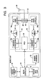
- FIG. 3 is a high level block diagram depicting the overall structure of a mobile unit used by the positioning system of FIG. 1;
- FIG. 4 is a high level block diagram depicting the overall structure of a fixed unit used by the positioning system of FIG. 1;
- FIG. 5 is a block diagram of the field programmable gate array used as part of the mobile and fixed units depicted in FIGS. 3 and 4;
- FIG. 6 is a block diagram of a coarse measurement circuit used by the positioning system of FIG. 1;
- FIG. 7 is a block diagram of a clock compare circuit used by the positioning system of FIG. 1;
- FIG. 8 is a block diagram of a skip detection circuit used by the positioning system of FIG. 1;
- FIG. 9 is a logic flow diagram depicting the logic implemented by the mobile unit of FIG. 3;
- FIG. 10 is a logic flow diagram depicting the logic implemented by the fixed unit of FIG. 4;
- FIG. 11 is a timing diagram depicting the relationships among the various signals employed to calculate the distances between the mobile unit and one or more of the fixed units.
- FIG. 12 is a system level block diagram similar to FIG. 1 showing the use of optional elements with the positioning system described herein.
- FIG. 1 of the drawing depicted therein as 20 is a positioning system constructed in accordance with, and embodying, the principles of the present invention.
- This system 20 comprises a mobile unit 22 and one or more fixed units 24 .
- the positioning system 20 may be used to find the distance between the mobile unit 22 and any one of the fixed units 24 and/or may be used to find the location of the mobile unit 22 relative to a plurality of the fixed units 24 .
- the positioning system 20 may be used in any environment in which precise distance and/or location information is important. Examples of environments in which the positioning system 20 may be used include construction sites, manufacturing facilities, the location of components of a utility system, location of ordinance, the tracking of vehicles or railroad cars, and facilities maintenance systems, and the like.
- the basic principles of the present invention may be implemented as a distancing system using a single mobile unit 22 and a single fixed unit 24 .
- a distancing system yields only distance data and not absolute position data.
- Distance data identifies a circular path about the mobile unit 22 .
- the fixed unit 24 is located somewhere on this circular path.
- the present invention may be used on a golf course to determine the distance between the golf ball and a golf pin; in this environment, the precise location of the mobile unit 22 relative to the pin is not important. Typically, the pin will be visible to a person standing at the ball. But knowledge of the precise distance between the golf ball and the golf pin may help the golfer select an appropriate club.
- the present invention will be described herein in the context of a positioning system that can identify the absolute position of the mobile unit on a predetermined coordinate system.
- a positioning system at least two and preferably three or more fixed units are required.
- the calculated distance data identifies two circular paths about the fixed units 24 . These circles will overlap at two locations, and the position of the mobile unit 22 can be identified as one of the two locations at which the circles intersect.
- external information may be used to eliminate one of these two locations as a possibility, thereby allowing the position of the mobile unit to be determined absolutely with only two fixed units 24 .
- FIG. 1 it is more likely that the present invention will be embodied as shown in FIG. 1, with one or more mobile units 22 and three or more fixed units 24 .
- the use of three or more fixed units will allow the location of the mobile unit to be established with reference to a two-dimensional coordinate system and without external information.
- the exemplary positioning system 20 employs four fixed units 24 a-d.
- the location of the mobile unit 22 can be determined with reference to a three dimensional coordinate system; for a three dimension coordinate system, at least three and preferably five or more fixed units 24 will be used.
- a three dimension coordinate system at least three and preferably five or more fixed units 24 will be used.
- the greater the number of fixed units the greater the accuracy of the distancing/positioning system incorporating the principals of the present invention.
- the mobile and fixed units 22 and 24 calculate distances based on radio frequency signals transmitted at two different frequencies as shown in FIG. 1 .
- the exact frequencies are not important to the application of the present invention in its broadest form and will be determined by such factors as government allocation of the frequency spectrum and like.
- the exemplary system 20 employs a first frequency of 2.412 GHz and a second frequency of 2.462 GHz.
- the mobile unit 22 sends information packets 26 to one or more of the fixed units 24 .
- the system 20 uses the data contained by the information and the propagation times of these packets 26 to determine distance and, in the case of the system 20 , position.
- each of the data or information packets 26 comprises instructions and data in a predetermined format.
- the exact content and format of the data packets 26 is not important to the principles of the present invention, and these data packets 26 will not be described herein beyond what is necessary for a complete understanding of the present invention.
- the information packets 26 may contain data for identifying the source and destination of the packet, commands, distance or position data, and the like. Other data, such as text messages, sensor data, or the like may also be included in the packets 26 if desired under the circumstances.
- the mobile unit first sends an Initialize Measurement cycle packet 26 a to all of the fixed units.
- the fixed units 24 initialize themselves in preparation for the measurement cycle, and the first fixed unit 24 sends a Response To Initialize data packet 26 to the mobile unit 22 to confirm that the Initialize Measurement cycle packet 26 a was received.
- the system 20 may be configured such that all of the fixed units 24 send a verifying Response to Initialize data packet.
- the mobile unit 22 next sends a First Measurement packet 26 c containing control commands and/or data information indicating that it is intended for the first fixed unit 24 a .
- the first fixed unit 24 a receives the First Measurement packet 26 c on a first frequency and retransmits this packet 26 c back to the mobile unit 22 on a second frequency.
- the mobile unit 22 then calculates the distance between its current location and the location of the first fixed unit 24 a . This process is repeated by sending Measurement Packets 26 d , 26 e , and 26 f to each of the other exemplary fixed units 24 b-d.
- the absolute location of the mobile unit 22 may be determined based on the predetermined locations of the fixed units 24 .
- the measurement cycle may be performed periodically or randomly to update the position of the mobile unit 22 .
- the mobile unit 22 comprises a controller 30 , memory 32 , and a logic circuit 34 embodied as a field programmable gate array (FPGA).
- FPGA field programmable gate array
- the logic circuit 34 may be embodied in forms other than a FPGA. The details of relevant portions of the exemplary logic circuit 34 will be described in further detail below.
- the exemplary mobile unit 22 also comprises optional command and data ports 36 and 38 . These data ports 36 and 38 are or may be conventional and will not be described in further detail.
- the mobile unit 22 further comprises a transmit circuit 40 and a receive circuit 42 .
- the transmit and receive circuits 40 and 42 are coupled to an antenna 44 through transmit and receive filter circuits 46 and 48 .
- the antenna 44 and filter circuits 46 and 48 are conventional and will not be described herein in further detail.
- FIG. 3 also shows that the transmit and receive circuits 40 and 42 each comprise a baseband processor 50 , an IF modulator 52 , and an RF stage 54 .
- the suffix (a) is associated with components of the transmit circuit 40
- the suffix (b) is associated with similar components of the received circuit 42 .
- the baseband processors 50 , IF modulators 52 , and RF stages 54 all are or may be conventional and will be described below only to the extent necessary for a complete understanding of the present invention.
- the mobile unit 22 employs two separate clock signals having slightly different frequencies to obtain distance calculations as will be described in further detail below. Because two clock signals are used, the transmit and receive circuits 40 and 42 use separate baseband processors 50 a and 50 b , respectively.
- the baseband processors 50 a,b , IF modulators 52 a,b , and RF stages 54 a,b are or may be conventional and will not be described herein in detail. Similar circuits are described in U.S. Pat. No. 6,067,039 to Pyner, and the disclosure of that patent is incorporated herein by reference.
- FIG. 4 depicted therein is a simplified block diagram of one of the fixed units 24 .
- the fixed units 24 will be identical, but it is possible to implement the invention with fixed units having different software and/or circuit topologies.
- the fixed units 24 are similar in many respects to the mobile unit 22 .
- the fixed units 24 comprise a controller 60 , memory 62 , and a logic circuit 64 implemented as an FPGA that may be identical to the FPGA containing the logic circuit 34 .
- a common FPGA to implement both of the logic circuits 34 and 64 creates manufacturing and maintenance efficiencies but is not required to implement the principles of the present invention in its broadest form.
- the fixed units 24 further optionally comprise a conventional data port 66 and a conventional LCD display 68 .
- the fixed unit 24 further comprise a transmit circuit 70 and a receive circuit 72 . These transmit and receive circuits 70 and 72 are coupled to a conventional antenna 74 by conventional filters 76 and 78 .
- the transmit circuit 70 comprises a baseband processor 80 , an IF modulator 82 a , and an RF stage 84 a .
- the receive circuit 72 comprises only an IF demodulator 82 b and an RF stage 84 b and does not employ a separate baseband processor.
- the fixed units 24 do not require two different clock signals with slightly different frequencies to obtain distance calculations. Because only one clock signal is required, the baseband processor 80 may be used for both transmit and receive functions.
- the fixed unit 24 further comprises a mode switch 90 that allows the fixed unit 24 to be placed in either a data mode or in a loopback mode.
- a mode switch 90 that allows the fixed unit 24 to be placed in either a data mode or in a loopback mode.
- the input to the RF stage 84 a is the IF modulator 82 a of the transmit circuit 70 .
- the input to the RF stage 84 a is the IF demodulator 82 b of the receive circuit 72 .
- the fixed unit 24 may receive and process data packets such as the Response to Initialize data packet 26 b described above.
- the fixed unit 24 When the fixed unit 24 is used to obtain distance information in the loopback mode, the fixed unit 24 functions as an RF repeater that simply retransmits RF signals received by the received circuit 72 .
- the RF signals will carry data packets such as the Measurement packets 26 c-f described above.
- the fixed units 24 may also use the baseband processor 80 to decode the data packet as the packet is being retransmitted. Other types of data may thus be transferred from the mobile unit 22 to the fixed unit 24 while the measurement calculations are performed.
- the fixed units 24 thus operate as simple repeaters that retransmit the received measurement packets 26 c-f without any baseband processing at the fixed units 24 .
- the baseband processor 80 , IF modulators 82 a,b , RF stages 84 a,b , and mode switch 90 also are may be conventional and will not be described herein in detail.
- the controllers 30 and 60 and memory 32 and 62 are or may be conventional and will not be described herein in detail.
- the controllers 30 and 60 may be any microprocessor capable of receiving data from and controlling the logic circuits 34 , 64 and the transmit and receive circuits 40 , 42 , 70 , and 72 as described herein.
- the controller 30 is also capable of performing the distance and location calculations recited herein.
- the memory devices 32 and 62 allow permanent and temporary storage of instructions and data as necessary to perform the control and calculation functions of the controllers 30 and 60 .
- the exemplary logic circuit 34 comprises a coarse measurement circuit 120 , a clock compare circuit 122 , and a skip detection circuit 124 .
- the FPGA used to implement the logic circuits 34 and 64 also contains a timer circuit, transmit and receive first-in/first-out (FIFO) circuits, and I/O port circuits.
- FIFO first-in/first-out
- I/O port circuits I/O port circuits.
- the coarse measurement, clock compare, and skip detection circuits 120 - 124 are all connected to a data bus 130 that is in turn connected to the controller 30 .
- the data bus 130 is or may be conventional and will not be described herein in detail.
- FIG. 5 also shows that each of these circuits 120 - 124 receives and/or generates one or more discrete signals as shown in FIG. 5 and as will be described in further detail below.
- Other signals are also received and/or generated by the logic circuit 34 in general and the circuits 120 - 124 in particular, but these other signals may be characterized as housekeeping signals and are not essential to an understanding of the present invention.
- the coarse measurement circuit 120 the clock compare circuit 122 , and skip detection circuit 124 generate numerical values that the controller 30 uses, as will be described in further detail below, to measure distance and/or position using the principles of the present invention.
- the logic circuit thus operates basically as follows.
- the coarse measurement circuit 120 generates a coarse measurement value.
- the transmit and receive circuits 40 and 42 of the fixed unit 22 use separate transmit and receive master clock signals CLK 1 and CLK 2 , both of which are located at the mobile unit 22 .
- the clock compare circuit 122 directly measures the phase difference between these two clock signals CLK 1 and CLK 2 .
- the skip detection circuit 124 calculates the frequency difference between the two clock signals CLK 1 and CLK 2 .
- the coarse measurement value is refined using the phase and frequency difference information to obtain a more accurate measurement of distance.
- the accuracy of the distance value calculated by the coarse measurement circuit 122 depends upon the frequencies of the clock signals used by the baseband processors 50 a,b .
- the exemplary coarse measurement circuit 120 is accurate only to within plus or minus eleven feet (44 MHz); in many environments, a higher level of accuracy is required.
- the controller 30 uses the numerical values generated by the clock compare circuit 122 and skip detection circuit 124 to increase the accuracy of the distance measurements generated by the system 20 .
- the clock compare circuit 122 and skip detection circuit 124 allow the system 20 to obtain distance measurements accurate to within plus or minus 20 centimeters without increasing the frequency of the baseband processor clock. In practice, it might be possible to improve the accuracy of the system 20 even more by taking multiple measurements and averaging and/or using a greater number of fixed units 24 .
- the coarse measurement circuit 120 clock compare circuit 122 , and skip detection circuit 124 will each be discussed separately below.
- the coarse measurement circuit 120 measures the period of time it takes for a data packet 26 to make the round trip between the mobile unit 22 and the fixed units 24 . This process is similar to the coarse measurement process used in U.S. Pat. No. 6,067,039 cited above. Circuits other than the circuit 120 described herein or the similar circuit described in the '039 patent may be used to perform this function. The scope of the present invention should thus not be limited to the particular implementation of the circuit 120 described herein.
- the coarse measurement circuit 120 measures the time it takes a data packet 26 generated at the mobile unit 22 to propagate to a selected one of the fixed units 24 , be retransmitted by the selected fixed unit 24 in the loopback mode, and then propagate back to the mobile unit 22 .
- the baseband processor 50 a of the mobile unit transmit circuit 40 generates a signal TX_RDY when the first data bit is transmitted.
- the receive baseband processor 50 b generates a signal MD_RDY that goes high when the first data bit retransmitted by the fixed unit 24 is received by the mobile unit 22 .
- These TX_RDY and MD_RDY signals are input to a counter 140 through flip-flops 142 a and 142 b and then through an XOR gate 144 .
- the flip-flops 142 a,b and XOR gate 144 result in a HIGH signal being generated at the ENABLE input of the counter 140 that generally corresponds to the round trip transit time of the measurement packets 26 c-f as generally described above.
- a 44 MHz clock signal is applied to the CLK input of the counter 140 .
- the counter 140 counts the number of CLK pulses that occur when the ENABLE input is held HIGH.
- the value of the counter 140 is applied to latches 146 a,b . These latches 146 a,b are in turn connected to the data bus 130 .
- the controller 30 thus may determine the numerical value of the counter 140 by downloading the values of the latches 146 a,b over the data bus 130 .
- the controller will read the latches 146 a,b at some point after the MD_RDY signal is generated, convert this numerical value into a time value based on the clock rate, and then convert this time value into a distance value using constants such as system delays and the propagation speed of electromagnetic waves.
- the distance value so obtained corresponds to the distance between the mobile unit 22 and any one of the fixed units 24 to a level of accuracy of approximately plus or minus eleven feet.
- the clock compare circuit 122 will now be described in further detail with reference to FIG. 7 .
- the principles of the present invention may be embodied by clock compare circuits other than the exemplary clock compare circuit 122 described used in the exemplary system 20 .
- the exemplary clock compare circuit 122 generates a frequency difference value that the controller uses to refine the coarse measurement value obtained by the coarse measurement circuit 120 .
- the clock compare circuit 122 generates a numerical value corresponding to the frequency difference between the clock signals CLK 1 and CLK 2 .
- the controller 30 uses the frequency difference value to determine when a given radio frequency signal was received in the previous half cycle of the receive clock CLK 2 . This information allows the controller 30 to refine the distance value measured by the coarse measurement circuit 120 as described above.
- the clock compare circuit 122 comprises an XOR gate 150 , a long pulsewidth detect circuit 152 , a first pair of latches 156 a and 156 b , and a second pair of latches 158 a and 158 b.
- the clock compare circuit 122 operates basically as follows.
- the two master clock signals CLK 1 and CLK 2 are passed through the exclusive XOR gate 150 .
- the output of the XOR gate 150 is high.
- the output of the exclusive XOR gate 150 is low.
- the relationship between the two clock signals CLK 1 and CLK 2 can be such that they are neither exactly out of phase or exactly in phase.
- the output of exclusive OR gate 150 may be a series of very short spikes or pulses.
- the output of the exclusive OR gate 150 is thus passed through a filter 151 .
- the filter 151 is separate from the FPGA defining the logic circuit 34 and this arrangement is illustrated by the conventions used in FIG. 7 .
- the use of an FPGA is optional and the filter may be connected to the output of the exclusive OR gate 150 using other techniques. In any event, the filter 151 eliminates the short duration pulses or spikes during the transition period when the clock signals CLK 1 and CLK 2 are slightly in or out of phase.
- the output of the exclusive OR gate 150 is subsequently input to the long pulsewidth detect circuit 152 .
- the clock signal CLK 1 is also applied to the clock input of the counter 154 .
- the clock signal CLK 1 is also applied to the clock input of the long pulsewidth detect circuit 152 . Accordingly, when the long pulsewidth detect circuit 152 determines that the output of the exclusive OR gate 150 stays high for a predetermined number of clock pulses, the counter 154 is reset and current value of the counter 154 is latched into the first pair of latches 156 a,b.
- the value stored by the first pair of latches 156 a,b corresponds to the number of pulses of the first clock signal CLK 1 in a given time period. In particular, this value corresponds to the number CLK 1 pulses generated in the time between when the two clock signals CLK 1 and CLK 2 are in phase and when the two clock signals CLK 1 and CLK 2 are next in phase.
- the controller 30 thus uses the numerical value stored in the first pair of latches 156 a,b to calculate the frequency difference between the two clock signals CLK 1 and CLK 2 .
- the second pair of latches 158 a,b are also connected to the counter 154 . However, the value of the counter 154 is latched into these latches 158 a,b when the receive baseband processor 50 b generates the MD_RDY signal upon receipt of the measurement pack 26 .
- the numerical value stored in the second pair of latches 158 a,b can thus be used in conjunction with the numerical value stored in the first set of latches 156 a,b to determine the exact phase relationship between the two clock signals CLK 1 and CLK 2 when the measurement packet is received by the receive baseband processor 50 b .
- the latch sets 156 a,b and 158 a,b are connected to the data bus 130 such that the controller 30 can read these values and use them to generate distance and position values.
- the exemplary skip detection circuit 124 is depicted therein in further detail.
- the transmit and receive clock signals CLK 1 and CLK 2 located at the mobile unit 22 are purposely set to differ by approximately 25 pulses per million. This difference between the transmit and receive clock signals CLK 1 and CLK 2 causes the baseband processing circuits 50 a,b to jump or skip to maintain synchronization with the incoming signal. This event is referred to herein as a “skip”.
- the receive baseband processor 50 b thus generates skip signals at a frequency corresponding to the frequency difference between the frequencies of the clock signals CLK 1 and CLK 2 .
- the skip detection circuit 124 detects these skip signals and generates a skip value as will be described in detail below.
- the exemplary skip detection circuit 124 is specifically designed to work with a given implementation of a baseband processor. Any implementation of a baseband processor as described herein will need to skip as defined herein to accommodate differing clock signals. However, the exact manner in which these skips are generated and detected may differ for different types or makes of baseband processor circuits, so the skip detection circuit would likely be implemented differently in other implementations of the present invention.
- the exemplary skip detection circuit comprises an AND gate 160 , an inverter 162 , first and second counters 164 a,b , first and second registers 166 a,b , first and second comparators 168 a,b , an OR gate 170 , a counter 172 , a pair of latches 174 a,b , a flip-flop 176 , a second inverter 178 , and a second AND gate 180 .
- the exemplary skip detection circuit 124 operates basically as follows.
- the skip detection circuit 124 analyzes the Rx_CLK signal generated by the receive baseband processor 50 b . If the transmit and receive clock signals CLK 1 and CLK 2 have the same frequency and are in phase, the Rx_CLK signal will always be consistent. In the exemplary positioning system 20 , the Rx_CLK signal would ideally be HIGH for four master clock pulses and LOW for twelve master clock pulses, but this ideal relationship could differ from one implementation to the next.
- the Rx_CLK signal must occasionally skip to keep the baseband processor circuit 50 b in synch. More specifically, a skip occurs when one Rx_CLK cycle is stretched or shrunk by one master clock (MCLK) pulse. For example, instead of the theoretical four MCLK high to twelve MCLK low relationship, a skip would create a five MCLK high and twelve MCLK low relationship.
- the skip detection circuit 124 monitors the Rx_CLK signal for the skips and generates a skip value corresponding to the time interval between the skips.
- the Rx_CLK signal is gated by the MD_RDY signal through the first AND gate 160 .
- the output of the AND gate 160 is passed directly to the first or “Hi time” counter 164 a and through the first inverter 162 to the second or “Low time” counter 164 b .
- the comparators 168 a and 168 b compare the values stored in the counters 164 a and 164 b with the values stored in the corresponding registers 166 a and 166 b .
- the values stored in the registers 166 a and 166 b correspond to the duration of one cycle of the Rx_CLK signal without skips.
- the controller 30 reads the value stored in one of the registers 166 a or 166 b over the data bus 130 as the skip value.
- FIG. 11 illustrates that the Tx_CLK and Rx_CLK signals have a slightly different frequency.
- FIG. 11 also shows that, while leading edge of the Tx_RDY signal may be generated to coincide,with the leading edge of one of the Tx_CLK signal pulses, the leading edge of the MD_RDY signal will likely be generated at a point in time corresponding to the leading edge of one of the Rx_CLK signals.
- the actual time of flight may differ from the generation of the MD_RDY signal as shown.
- the coarse measurement value is computed based on the number of Tx_CLK signals that occur between the generation of the Tx_RDY signal and the generation of the MD_RDY signal; in the example shown, the coarse measurement value corresponds to seven Tx_CLK periods. The difference between the Tx_CLK and Rx_CLK signals thus introduces an error of up to one Tx_CLK period, creating an error in the coarse measurement value as described above and in U.S. Pat. No. 6,067,039 cited above.
- FIG. 11 further shows that the output of the XOR gate 150 of the clock compare circuit 122 is monitored to determine the frequency difference value (Freq Diff Count) and the phase count value (Phase Count) described above.
- the ratio of the phase count value to the frequency difference value corresponds to the ratio of the phase difference between the Tx_CLK and Rx_CLK signals and the period of the transmit clock signal Tx_CLK. Since the period of the transmit clock signal Tx_CLK is predetermined, the phase difference between the Tx_CLK and Rx_CLK signals may be calculated with a high degree of accuracy.
- the fine measurement value is thus calculated based on the phase difference determined by the clock compare circuit 122 , the phase determined by the skip detection circuit 124 , and the frequency difference determined by the clock compare circuit 122 .
- the fine measurement value may be combined with the coarse measurement value to obtain a distance value that may be converted to a time value closely corresponding to the time of flight.
- the processors 30 and 60 of the mobile and fixed units 22 and 24 operate under the control of software programs that determines how the received packets are processed.
- the packet processing systems implemented in software running on each of the processors 30 and 32 will now be described in further detail.
- FIG. 9 depicted therein is a logic flow diagram illustrating a packet processing system 210 implemented by the mobile unit 22 .
- the mobile unit 22 waits for a measurement request, which may be generated locally or received from a remote host.
- the mobile unit 22 broadcasts a system control packet 26 g that notifies the fixed units 24 that the mobile unit 22 will be sending measurements packets.
- the mobile unit 22 sends measurement packets 26 c-f intended for the fixed units 24 a-d , respectfully.
- the measurement packets 26 c-f are sent sequentially and contain information that, as will be described in further detail below, allows the fixed units 24 to identify whether the packet is intended therefore and, if so, to retransmit the packet in loopback mode.
- the mobile unit 22 and the given fixed unit 24 are configured to receive and transmit substantially simultaneously.
- FIG. 10 depicted therein is a logic flow diagram illustrating a packet processing system 212 implemented by the fixed units 24 .
- the fixed units 24 are normally in a sleep mode in which they wait for an incoming system control packet.
- the mode switch 90 is set such that the fixed unit 24 is in its data mode rather than in its loopback mode.
- Step 242 shows the receipt of an incoming packet.
- the type and purpose of the incoming packet are not determined, and the system 212 next moves to a step 244 .
- the fixed unit 24 determines whether a received packet is a control packet associated with the particular fixed unit. If not, the process returns to step 240 and waits for another packet.
- step 246 the packet is analyzed to determine whether the measurement cycle is being initiated. If not, the control packet is assumed to include a command, and the system 212 processes the command at step 250 . The system 212 further determines at step 252 whether a response is required. If not, the system 212 simply returns to step 240 . If so, the system 212 moves to step 254 at which the appropriate response is compiled and sent to the mobile unit 22 in a response packet 26 h . The system 212 then returns to step 240 .
- the system 212 determines that the control packet is associated with or initiates a measurement cycle, the system 212 moves to steps 260 - 268 .
- the packet processing system 212 described with reference to FIG. 10 may vary somewhat from one fixed unit to another.
- the mobile unit 22 and fixed units 24 employ one transmit frequency and one receive frequency, the distance measurements from the mobile unit 22 to the fixed units 24 are calculated sequentially as generally shown in FIG. 9 described above. Accordingly, each fixed unit 24 must determine when it should enter the loopback mode in which the next received packet is simply retransmitted to the mobile unit 22 without being downconverted and processed.
- the fixed units 24 are assigned an arbitrary place in the sequence illustrated in FIG. 9 .
- the first measurement packet 26 c is intended to be retransmitted by the first fixed 24 a
- the second measurement packet 26 d is intended to be retransmitted by the second fixed unit 24 b
- Steps 260 - 268 illustrated in FIG. 10 show how the third fixed unit 24 c processes measurement packets to determine when to enter the loopback mode and retransmit the third measurement packet 26 e to the mobile unit 22 to allow the mobile unit 22 to calculate distance to the third fixed unit 24 c.
- the third fixed unit 24 c will listen to the received measurement packet and, at step 262 , determine whether the received packet is the first measurement packet 26 c intended for the first fixed unit 24 a . If not, the system 212 returns to step 240 . If the packet is the first measurement packet 26 c , the system 212 moves to step 264 to listen for the next packet. If, as shown at step 266 , the next packet is the second measurement packet 260 d intended for the second fixed unit 24 b , the system 212 is placed in its loopback mode as shown at step 268 . If the received packet analyzed at step 266 is not the second measurement packet 26 d , the system 212 returns to step 240 .
- the third measurement packet 26 e will simply be retransmitted directly through the RF circuitry.
- the measurement packet 263 may be converted to the baseband frequency and processed to extract data therefrom as generally discussed above.
- this substantially simultaneous retransmission of the third measurement packet 26 e eliminates a number of variables that may affect the accuracy of the overall system 20 .
- the packet would be received and retransmitted a predetermined time period thereafter. This predetermined time period introduced error due to clock drift and the like.
- the primary delay in the system 20 is introduced by the demodulator 82 b , loopback switch 90 , and modulator 86 , and this delay may be considered zero for the purposes of calculating distancing information.
- the packet processing system 212 implemented by the first fixed unit 24 a enters the loopback mode as soon as the system 212 determines at step 246 that the received packet is initiating the measurement cycle.
- the second fixed unit 24 b would enter the loopback mode after it was determined at step 262 that the packet detected at 260 is intended for the first fixed unit 24 a .
- the fourth and any subsequent fixed units would also monitor the measurement packets to determine whether the packet is intended for the fixed unit immediately prior in the arbitrary numbering of the fixed units 24 .
- each fixed unit 24 may enter the loopback mode a predetermined time period after it is determined at step 246 that the system is entering the measurement cycle.
- the predetermined delay would differ for each of fixed units 24 and would be calculated to place each of the fixed units 24 in the loopback mode at the appropriate time.
- the data collection system 320 comprises a mobile unit 322 and a plurality of fixed units 324 that may be constructed in the same manner as the mobile unit 22 and fixed units 24 described above.
- the data collection system 320 comprises a sensor control and data collector module 330 and a plurality of sensors 332 .
- the sensor control and data collector 330 and sensors 332 are adjacent or attached to the mobile unit 322 .
- the exemplary data collection system 320 further comprises a data logger 334 located, for example, at the fixed unit 324 a.
- the sensors 332 may be any sensing device capable of generating an electrical signal based on an environmental factor. Such sensors may detect the presence or absence of substances, electromagnetic radiation, or the like.
- the electrical signals generated by the sensors 332 are processed by the sensor control and data collector module 330 and organized into data packets that may be transmitted by the mobile unit 322 .
- these data packets are transmitted to the fixed unit 324 where the data may be logged and/or processed by the data logger 334 .
- the mobile unit 322 may continually determine its position and send this position information also to the fixed unit 324 a .
- the data detected by the sensors 332 is combined with the position data determined by the mobile unit 322 using a positioning system such as the positioning system of the present invention described above.
Abstract
Description
Claims (1)
Priority Applications (1)
| Application Number | Priority Date | Filing Date | Title |
|---|---|---|---|
| US10/420,641 US6744398B1 (en) | 2002-04-19 | 2003-04-21 | Distancing and positioning systems and methods |
Applications Claiming Priority (2)
| Application Number | Priority Date | Filing Date | Title |
|---|---|---|---|
| US37423102P | 2002-04-19 | 2002-04-19 | |
| US10/420,641 US6744398B1 (en) | 2002-04-19 | 2003-04-21 | Distancing and positioning systems and methods |
Publications (1)
| Publication Number | Publication Date |
|---|---|
| US6744398B1 true US6744398B1 (en) | 2004-06-01 |
Family
ID=32328879
Family Applications (1)
| Application Number | Title | Priority Date | Filing Date |
|---|---|---|---|
| US10/420,641 Expired - Lifetime US6744398B1 (en) | 2002-04-19 | 2003-04-21 | Distancing and positioning systems and methods |
Country Status (1)
| Country | Link |
|---|---|
| US (1) | US6744398B1 (en) |
Cited By (20)
| Publication number | Priority date | Publication date | Assignee | Title |
|---|---|---|---|---|
| US20030143969A1 (en) * | 2002-01-22 | 2003-07-31 | Buznitsky Mitchell A. | Determination and processing for fractional-N programming values |
| US20060061469A1 (en) * | 2004-09-21 | 2006-03-23 | Skyfence Inc. | Positioning system that uses signals from a point source |
| US7050507B2 (en) * | 2002-04-22 | 2006-05-23 | Intel Corporation | Adaptive throughput pulse width modulation communication scheme |
| US20060176178A1 (en) * | 2005-01-27 | 2006-08-10 | Everest A W | Device for monitoring and measuring distance |
| US20080284564A1 (en) * | 2004-07-07 | 2008-11-20 | Koninklijke Philips Electronics, N.V. | Time-of-Flight Ranging Systems |
| US20100330984A1 (en) * | 2009-06-29 | 2010-12-30 | Samsung Electronics Co., Ltd. | User equipment and cell search method for the same background of the invention |
| EP2196823B1 (en) * | 2008-12-12 | 2011-06-15 | Lambda: 4 Entwicklungen GmbH | Method for determining the distance between two objects |
| US20110221632A1 (en) * | 2010-03-09 | 2011-09-15 | Ensco, Inc. | High-precision radio frequency ranging system |
| US20120019413A1 (en) * | 2010-07-26 | 2012-01-26 | Ensco, Inc. | System and method for real-time locating |
| US20130072217A1 (en) * | 2011-09-19 | 2013-03-21 | Qualcomm Atheros, Inc. | Time of arrival based positioning system |
| US8457655B2 (en) | 2011-09-19 | 2013-06-04 | Qualcomm Incorporated | Hybrid time of arrival based positioning system |
| US8489114B2 (en) | 2011-09-19 | 2013-07-16 | Qualcomm Incorporated | Time difference of arrival based positioning system |
| US8509809B2 (en) | 2011-06-10 | 2013-08-13 | Qualcomm Incorporated | Third party device location estimation in wireless communication networks |
| US8547870B2 (en) | 2011-06-07 | 2013-10-01 | Qualcomm Incorporated | Hybrid positioning mechanism for wireless communication devices |
| US8755304B2 (en) | 2011-10-21 | 2014-06-17 | Qualcomm Incorporated | Time of arrival based positioning for wireless communication systems |
| US8824325B2 (en) | 2011-12-08 | 2014-09-02 | Qualcomm Incorporated | Positioning technique for wireless communication system |
| US8909244B2 (en) | 2011-06-28 | 2014-12-09 | Qualcomm Incorporated | Distributed positioning mechanism for wireless communication devices |
| EP3078934A1 (en) * | 2015-04-10 | 2016-10-12 | MTS Maschinentechnik Schrode AG | Measuring system and measuring method |
| EP3722831A1 (en) | 2019-04-10 | 2020-10-14 | Stichting IMEC Nederland | Method of wireless ranging |
| US11368183B2 (en) * | 2019-06-21 | 2022-06-21 | Ensco, Inc. | Systems and methods for synchronizing time, frequency, and phase among a plurality of devices |
Citations (30)
| Publication number | Priority date | Publication date | Assignee | Title |
|---|---|---|---|---|
| US3613095A (en) | 1969-06-16 | 1971-10-12 | Albert A Elwood | Method of and apparatus for locating a position |
| US3787846A (en) | 1972-08-10 | 1974-01-22 | Us Navy | Close-in ranger system |
| US3797015A (en) | 1969-06-16 | 1974-03-12 | A Elwood | Method of and system for locating a position |
| US3816832A (en) | 1969-06-16 | 1974-06-11 | A Elwood | Radio receiving station |
| US3839719A (en) | 1969-06-16 | 1974-10-01 | A Elwood | Radio transmitting station |
| US3868692A (en) | 1973-09-13 | 1975-02-25 | Roland L Woodard | Golf yardage finder |
| US3916410A (en) | 1969-06-16 | 1975-10-28 | Albert A Elwood | Method of and system for locating a position |
| US4128835A (en) * | 1977-08-23 | 1978-12-05 | Arinc Research Corporation | Method and apparatus for measuring distance between an aircraft and a ground station |
| US4136394A (en) | 1977-09-23 | 1979-01-23 | Joseph Jones | Golf yardage indicator system |
| US4278977A (en) | 1979-05-04 | 1981-07-14 | Rca Corporation | Range determining system |
| US4297701A (en) | 1979-08-08 | 1981-10-27 | John D. Angleman | Rangefinder using expanded time delay |
| DE3131188A1 (en) | 1981-08-06 | 1983-02-24 | Siemens AG, 1000 Berlin und 8000 München | System for interference-proof two-way communication |
| DE3324693A1 (en) | 1983-07-08 | 1985-01-24 | Prakla-Seismos Gmbh, 3000 Hannover | Method for measuring the two-way radio-frequency delay |
| US4513285A (en) | 1981-08-03 | 1985-04-23 | Sperry Corporation | Quasi coherent two-way ranging apparatus |
| US4703444A (en) | 1983-08-01 | 1987-10-27 | Spymark, Incorporated | Systems for determining distances to and locations of features on a golf course |
| US5044634A (en) | 1988-03-21 | 1991-09-03 | Yardmark, Inc. | Golf information system |
| US5046839A (en) | 1990-07-30 | 1991-09-10 | Locker Enterprises, Inc. | Golf course range finder system |
| US5056106A (en) | 1990-08-02 | 1991-10-08 | Wang James J | Golf course ranging and direction-finding system using spread-spectrum radiolocation techniques |
| US5095430A (en) | 1989-01-23 | 1992-03-10 | Joseph W. Remedio | Golf cart computer with cartridge storage |
| GB2249448A (en) | 1990-10-30 | 1992-05-06 | Roke Manor Research | Stepped frequency radar |
| US5298904A (en) | 1992-08-04 | 1994-03-29 | Olich Kirk J | Distance measuring system |
| US5311271A (en) | 1992-01-21 | 1994-05-10 | Dme/Golf, Inc. | Golf course range finder |
| JPH0827162A (en) | 1994-07-12 | 1996-01-30 | Shin Etsu Chem Co Ltd | Production of cyclic organosilicon compound |
| JPH08166444A (en) | 1994-12-16 | 1996-06-25 | Toyota Central Res & Dev Lab Inc | Two frequency cw radar sensor |
| US5582566A (en) | 1994-07-19 | 1996-12-10 | Furuno Electric Co., Ltd. | Range-finding system |
| US5652534A (en) | 1995-12-21 | 1997-07-29 | Hughes Aircraft Company | Precision digital phase shifter |
| US5691922A (en) | 1995-11-14 | 1997-11-25 | Airwave Technology, Inc. | Golf autoranging system |
| EP0809118A1 (en) | 1996-05-20 | 1997-11-26 | Delco Electronics Corporation | Continuous wave wideband precision ranging radar |
| US5912644A (en) | 1997-08-05 | 1999-06-15 | Wang; James J. M. | Spread spectrum position determination, ranging and communication system |
| US6067039A (en) * | 1998-11-30 | 2000-05-23 | Pacific Design Engineering (1996 ( Ltd. | Systems and methods for determining the distance between two locations |
-
2003
- 2003-04-21 US US10/420,641 patent/US6744398B1/en not_active Expired - Lifetime
Patent Citations (31)
| Publication number | Priority date | Publication date | Assignee | Title |
|---|---|---|---|---|
| US3916410A (en) | 1969-06-16 | 1975-10-28 | Albert A Elwood | Method of and system for locating a position |
| US3613095A (en) | 1969-06-16 | 1971-10-12 | Albert A Elwood | Method of and apparatus for locating a position |
| US3797015A (en) | 1969-06-16 | 1974-03-12 | A Elwood | Method of and system for locating a position |
| US3816832A (en) | 1969-06-16 | 1974-06-11 | A Elwood | Radio receiving station |
| US3839719A (en) | 1969-06-16 | 1974-10-01 | A Elwood | Radio transmitting station |
| US3787846A (en) | 1972-08-10 | 1974-01-22 | Us Navy | Close-in ranger system |
| US3868692A (en) | 1973-09-13 | 1975-02-25 | Roland L Woodard | Golf yardage finder |
| US4128835A (en) * | 1977-08-23 | 1978-12-05 | Arinc Research Corporation | Method and apparatus for measuring distance between an aircraft and a ground station |
| US4136394A (en) | 1977-09-23 | 1979-01-23 | Joseph Jones | Golf yardage indicator system |
| US4278977A (en) | 1979-05-04 | 1981-07-14 | Rca Corporation | Range determining system |
| US4297701A (en) | 1979-08-08 | 1981-10-27 | John D. Angleman | Rangefinder using expanded time delay |
| US4513285A (en) | 1981-08-03 | 1985-04-23 | Sperry Corporation | Quasi coherent two-way ranging apparatus |
| DE3131188A1 (en) | 1981-08-06 | 1983-02-24 | Siemens AG, 1000 Berlin und 8000 München | System for interference-proof two-way communication |
| DE3324693A1 (en) | 1983-07-08 | 1985-01-24 | Prakla-Seismos Gmbh, 3000 Hannover | Method for measuring the two-way radio-frequency delay |
| US4703444A (en) | 1983-08-01 | 1987-10-27 | Spymark, Incorporated | Systems for determining distances to and locations of features on a golf course |
| US5044634A (en) | 1988-03-21 | 1991-09-03 | Yardmark, Inc. | Golf information system |
| US5095430A (en) | 1989-01-23 | 1992-03-10 | Joseph W. Remedio | Golf cart computer with cartridge storage |
| US5046839A (en) | 1990-07-30 | 1991-09-10 | Locker Enterprises, Inc. | Golf course range finder system |
| US5056106A (en) | 1990-08-02 | 1991-10-08 | Wang James J | Golf course ranging and direction-finding system using spread-spectrum radiolocation techniques |
| GB2249448A (en) | 1990-10-30 | 1992-05-06 | Roke Manor Research | Stepped frequency radar |
| US5311271A (en) | 1992-01-21 | 1994-05-10 | Dme/Golf, Inc. | Golf course range finder |
| US5298904A (en) | 1992-08-04 | 1994-03-29 | Olich Kirk J | Distance measuring system |
| JPH0827162A (en) | 1994-07-12 | 1996-01-30 | Shin Etsu Chem Co Ltd | Production of cyclic organosilicon compound |
| US5582566A (en) | 1994-07-19 | 1996-12-10 | Furuno Electric Co., Ltd. | Range-finding system |
| JPH08166444A (en) | 1994-12-16 | 1996-06-25 | Toyota Central Res & Dev Lab Inc | Two frequency cw radar sensor |
| US5691922A (en) | 1995-11-14 | 1997-11-25 | Airwave Technology, Inc. | Golf autoranging system |
| US5652534A (en) | 1995-12-21 | 1997-07-29 | Hughes Aircraft Company | Precision digital phase shifter |
| EP0809118A1 (en) | 1996-05-20 | 1997-11-26 | Delco Electronics Corporation | Continuous wave wideband precision ranging radar |
| US5912644A (en) | 1997-08-05 | 1999-06-15 | Wang; James J. M. | Spread spectrum position determination, ranging and communication system |
| US6067039A (en) * | 1998-11-30 | 2000-05-23 | Pacific Design Engineering (1996 ( Ltd. | Systems and methods for determining the distance between two locations |
| WO2000033103A1 (en) * | 1998-11-30 | 2000-06-08 | Pacific Design Engineering (1996) Ltd. | Systems and methods for determining the distance between two locations |
Non-Patent Citations (4)
| Title |
|---|
| Ferraro & Boccignone, "Information proties in fine-to-course image transformations", Image Processing, 1998. ICIP 98. Proceedings. 1998 Int'l Conference on vol. 2, 1998 pp. 757-761 vol. 2. |
| Miller, Grenander, O'Sullivan & Snyder, "Automatic target recognition organized via jump-diffusion algorithms", Image Processing, IEEE Transactions on vol. 6 Jan. 1, 1997, pp. 157-174. |
| Pentland, Darrell, Turk & Huang, "A simple, real-time range camera", Computer Vision and Pattern Recognition, 1989. Proceedings CVPR '89., IEEE Computer Society Conference on 1989 pp 256-261. |
| Rabideau & Steinhardt, "Fast subspace tracking using course grain and fine grain parallelism", Acoustics, Speech, and Signal Processing, 1995. ICASSP-95 1995 Int'l Conference on vol. 5 1995 pp. 3211-3214 vol. 5. |
Cited By (30)
| Publication number | Priority date | Publication date | Assignee | Title |
|---|---|---|---|---|
| US6993306B2 (en) * | 2002-01-22 | 2006-01-31 | Broadcom Corporation | Determination and processing for fractional-N programming values |
| US20030143969A1 (en) * | 2002-01-22 | 2003-07-31 | Buznitsky Mitchell A. | Determination and processing for fractional-N programming values |
| US7050507B2 (en) * | 2002-04-22 | 2006-05-23 | Intel Corporation | Adaptive throughput pulse width modulation communication scheme |
| US7978049B2 (en) * | 2004-07-07 | 2011-07-12 | Koninklijke Philips Electronics N.V. | Time-of-flight ranging systems using coarse and fine measurements |
| US20080284564A1 (en) * | 2004-07-07 | 2008-11-20 | Koninklijke Philips Electronics, N.V. | Time-of-Flight Ranging Systems |
| US20060061469A1 (en) * | 2004-09-21 | 2006-03-23 | Skyfence Inc. | Positioning system that uses signals from a point source |
| US20060176178A1 (en) * | 2005-01-27 | 2006-08-10 | Everest A W | Device for monitoring and measuring distance |
| US7385513B2 (en) | 2005-01-27 | 2008-06-10 | Everest A Wallace | Device for monitoring and measuring distance |
| EP2196823B1 (en) * | 2008-12-12 | 2011-06-15 | Lambda: 4 Entwicklungen GmbH | Method for determining the distance between two objects |
| US8630639B2 (en) * | 2009-06-29 | 2014-01-14 | Samsung Electronics Co., Ltd. | User equipment and cell search method for the same |
| US20100330984A1 (en) * | 2009-06-29 | 2010-12-30 | Samsung Electronics Co., Ltd. | User equipment and cell search method for the same background of the invention |
| US8199047B2 (en) | 2010-03-09 | 2012-06-12 | Ensco, Inc. | High-precision radio frequency ranging system |
| US8314731B2 (en) | 2010-03-09 | 2012-11-20 | Ensco, Inc. | High-precision radio frequency ranging system |
| US20110221632A1 (en) * | 2010-03-09 | 2011-09-15 | Ensco, Inc. | High-precision radio frequency ranging system |
| US20120019413A1 (en) * | 2010-07-26 | 2012-01-26 | Ensco, Inc. | System and method for real-time locating |
| US8334801B2 (en) * | 2010-07-26 | 2012-12-18 | Ensco, Inc. | System and method for real-time locating |
| US8547870B2 (en) | 2011-06-07 | 2013-10-01 | Qualcomm Incorporated | Hybrid positioning mechanism for wireless communication devices |
| US8509809B2 (en) | 2011-06-10 | 2013-08-13 | Qualcomm Incorporated | Third party device location estimation in wireless communication networks |
| US8909244B2 (en) | 2011-06-28 | 2014-12-09 | Qualcomm Incorporated | Distributed positioning mechanism for wireless communication devices |
| US20130072217A1 (en) * | 2011-09-19 | 2013-03-21 | Qualcomm Atheros, Inc. | Time of arrival based positioning system |
| US8521181B2 (en) * | 2011-09-19 | 2013-08-27 | Qualcomm Incorporated | Time of arrival based positioning system |
| US8489114B2 (en) | 2011-09-19 | 2013-07-16 | Qualcomm Incorporated | Time difference of arrival based positioning system |
| US8457655B2 (en) | 2011-09-19 | 2013-06-04 | Qualcomm Incorporated | Hybrid time of arrival based positioning system |
| US9332383B2 (en) | 2011-09-19 | 2016-05-03 | Qualcomm Incorporated | Time of arrival based positioning system |
| US8755304B2 (en) | 2011-10-21 | 2014-06-17 | Qualcomm Incorporated | Time of arrival based positioning for wireless communication systems |
| US8824325B2 (en) | 2011-12-08 | 2014-09-02 | Qualcomm Incorporated | Positioning technique for wireless communication system |
| EP3078934A1 (en) * | 2015-04-10 | 2016-10-12 | MTS Maschinentechnik Schrode AG | Measuring system and measuring method |
| EP3722831A1 (en) | 2019-04-10 | 2020-10-14 | Stichting IMEC Nederland | Method of wireless ranging |
| US11368183B2 (en) * | 2019-06-21 | 2022-06-21 | Ensco, Inc. | Systems and methods for synchronizing time, frequency, and phase among a plurality of devices |
| US11804871B2 (en) | 2019-06-21 | 2023-10-31 | Ensco, Inc. | Systems and methods for synchronizing time, frequency, and phase among a plurality of devices |
Similar Documents
| Publication | Publication Date | Title |
|---|---|---|
| US6744398B1 (en) | Distancing and positioning systems and methods | |
| US10520582B2 (en) | Method for iterative target location in a multiple receiver target location system | |
| KR101182900B1 (en) | Symmetrical multipath method for determining the distance between two transceivers | |
| EP3315995A2 (en) | Time of arrival estimation | |
| CN1790049B (en) | Node position measuring system, wireless base station and position measuring method | |
| USRE36791E (en) | Location system adapted for use in multipath environments | |
| WO2018098606A1 (en) | High-precision synchronous data transmission method and device for vibration monitoring system collaboratively using ethernet and serial port rs-232 | |
| CN108401445B (en) | Circuit, method and related chip, system and equipment for measuring time | |
| US20090047976A1 (en) | Radio positioning system | |
| CN102904766B (en) | Baud rate identification method and device for serial communication and monitoring equipment | |
| CN106170951B (en) | Method for testing multiple data packet signal transceivers using a shared tester | |
| JPH04128676A (en) | Movement body discrimination equipment | |
| JP2003067124A (en) | Position detector | |
| JPH10282204A (en) | Location detecting equipment of moving body | |
| AU2022241595B2 (en) | Location awareness system | |
| JPH0359482A (en) | Position detecting system | |
| CN114706036A (en) | Method, device and equipment for detecting ranging value between equipment | |
| JPH0146034B2 (en) | ||
| EP0381878A1 (en) | Network diagnosis apparatus and method | |
| US8334716B1 (en) | Digital phase detection circuit and method | |
| KR100735407B1 (en) | Apparatus and method for estimating distance using time of arrival | |
| CN106559156A (en) | The method and apparatus of clock frequency identification | |
| WO2015073400A1 (en) | System and method for data packet transceiver testing after signal calibration and power settling to minimize test time | |
| US20220365201A1 (en) | Time-of-flight measurement system and method | |
| US20090028077A1 (en) | Method of determining the location of a node in a distributed wireless sensor and actuator network |
Legal Events
| Date | Code | Title | Description |
|---|---|---|---|
| STCF | Information on status: patent grant |
Free format text: PATENTED CASE |
|
| FEPP | Fee payment procedure |
Free format text: PAT HOLDER NO LONGER CLAIMS SMALL ENTITY STATUS, ENTITY STATUS SET TO UNDISCOUNTED (ORIGINAL EVENT CODE: STOL); ENTITY STATUS OF PATENT OWNER: LARGE ENTITY |
|
| AS | Assignment |
Owner name: ENSCO, INC., CALIFORNIA Free format text: ASSIGNMENT OF ASSIGNORS INTEREST;ASSIGNOR:PACIFIC DESIGN ENGINEERING;REEL/FRAME:020083/0623 Effective date: 20071002 |
|
| FPAY | Fee payment |
Year of fee payment: 4 |
|
| REMI | Maintenance fee reminder mailed | ||
| AS | Assignment |
Owner name: PACIFIC DESIGN ENGINEERING, CANADA Free format text: ASSIGNMENT OF ASSIGNORS INTEREST;ASSIGNORS:PYNER, DEREK J.;FRETENBURG, RUSSELL;KAZEMIR, STEVEN S. J.;REEL/FRAME:021590/0407 Effective date: 20080715 |
|
| AS | Assignment |
Owner name: PACIFIC DESIGN ENGINEERING, CANADA Free format text: ASSIGNMENT OF ASSIGNORS INTEREST;ASSIGNORS:FRETENBURG, RUSSELL;PYNER, DEREK J.;KAZEMIR, STEVEN S.J.;REEL/FRAME:021936/0590 Effective date: 20080715 |
|
| FPAY | Fee payment |
Year of fee payment: 8 |
|
| FPAY | Fee payment |
Year of fee payment: 12 |