US6679871B2 - Inflatable cannula and method of using same - Google Patents
Inflatable cannula and method of using same Download PDFInfo
- Publication number
- US6679871B2 US6679871B2 US09/751,445 US75144500A US6679871B2 US 6679871 B2 US6679871 B2 US 6679871B2 US 75144500 A US75144500 A US 75144500A US 6679871 B2 US6679871 B2 US 6679871B2
- Authority
- US
- United States
- Prior art keywords
- cannula
- balloon
- lumen
- elongate
- expandable
- Prior art date
- Legal status (The legal status is an assumption and is not a legal conclusion. Google has not performed a legal analysis and makes no representation as to the accuracy of the status listed.)
- Expired - Lifetime
Links
Images


Classifications
-
- A—HUMAN NECESSITIES
- A61—MEDICAL OR VETERINARY SCIENCE; HYGIENE
- A61M—DEVICES FOR INTRODUCING MEDIA INTO, OR ONTO, THE BODY; DEVICES FOR TRANSDUCING BODY MEDIA OR FOR TAKING MEDIA FROM THE BODY; DEVICES FOR PRODUCING OR ENDING SLEEP OR STUPOR
- A61M25/00—Catheters; Hollow probes
- A61M25/10—Balloon catheters
-
- A—HUMAN NECESSITIES
- A61—MEDICAL OR VETERINARY SCIENCE; HYGIENE
- A61B—DIAGNOSIS; SURGERY; IDENTIFICATION
- A61B17/00—Surgical instruments, devices or methods, e.g. tourniquets
- A61B17/12—Surgical instruments, devices or methods, e.g. tourniquets for ligaturing or otherwise compressing tubular parts of the body, e.g. blood vessels, umbilical cord
- A61B17/12022—Occluding by internal devices, e.g. balloons or releasable wires
- A61B17/12099—Occluding by internal devices, e.g. balloons or releasable wires characterised by the location of the occluder
- A61B17/12109—Occluding by internal devices, e.g. balloons or releasable wires characterised by the location of the occluder in a blood vessel
-
- A—HUMAN NECESSITIES
- A61—MEDICAL OR VETERINARY SCIENCE; HYGIENE
- A61B—DIAGNOSIS; SURGERY; IDENTIFICATION
- A61B17/00—Surgical instruments, devices or methods, e.g. tourniquets
- A61B17/12—Surgical instruments, devices or methods, e.g. tourniquets for ligaturing or otherwise compressing tubular parts of the body, e.g. blood vessels, umbilical cord
- A61B17/12022—Occluding by internal devices, e.g. balloons or releasable wires
- A61B17/12131—Occluding by internal devices, e.g. balloons or releasable wires characterised by the type of occluding device
- A61B17/12136—Balloons
-
- A—HUMAN NECESSITIES
- A61—MEDICAL OR VETERINARY SCIENCE; HYGIENE
- A61B—DIAGNOSIS; SURGERY; IDENTIFICATION
- A61B17/00—Surgical instruments, devices or methods, e.g. tourniquets
- A61B17/00234—Surgical instruments, devices or methods, e.g. tourniquets for minimally invasive surgery
- A61B2017/00238—Type of minimally invasive operation
- A61B2017/00243—Type of minimally invasive operation cardiac
-
- A—HUMAN NECESSITIES
- A61—MEDICAL OR VETERINARY SCIENCE; HYGIENE
- A61B—DIAGNOSIS; SURGERY; IDENTIFICATION
- A61B17/00—Surgical instruments, devices or methods, e.g. tourniquets
- A61B2017/00535—Surgical instruments, devices or methods, e.g. tourniquets pneumatically or hydraulically operated
- A61B2017/00557—Surgical instruments, devices or methods, e.g. tourniquets pneumatically or hydraulically operated inflatable
-
- A—HUMAN NECESSITIES
- A61—MEDICAL OR VETERINARY SCIENCE; HYGIENE
- A61M—DEVICES FOR INTRODUCING MEDIA INTO, OR ONTO, THE BODY; DEVICES FOR TRANSDUCING BODY MEDIA OR FOR TAKING MEDIA FROM THE BODY; DEVICES FOR PRODUCING OR ENDING SLEEP OR STUPOR
- A61M25/00—Catheters; Hollow probes
- A61M25/10—Balloon catheters
- A61M2025/1043—Balloon catheters with special features or adapted for special applications
- A61M2025/1052—Balloon catheters with special features or adapted for special applications for temporarily occluding a vessel for isolating a sector
Definitions
- This invention relates generally to a cannula or catheter that can be introduced to a small port and be inflated to accommodate a large flow of fluids, or can serve as a conduit or port to apply other medical therapy, such as surgical instruments, dilatation catheters, atherectomy devices, filters, aspirators, and pressure monitors.
- Minimally invasive surgical procedures which use an endoscopic approach have been widely used in many surgical specialties, including cardiothoracic surgery.
- New surgical techniques and instruments have been developed especially to assist in minimally invasive coronary bypass grafting.
- This procedure is often performed using the port access approach where a minimal access incision is made in the intercostal space rather than the traditional midstemotomy approach, therefore minimizing trauma to the chest wall.
- various instruments can be inserted through the incision and various tissue layers to reach the heart and great vessels.
- This peripherally-based system achieves aortic occlusion, cardioplegia delivery, and left ventricular decompression; thus, coronary revascularization and various cardiac procedures can be effectively performed.
- a rigid trocar provides adequate luminal dimension; however, it is also limited in its ability to expand and provide easy access. Therefore, a need exists for a fluid or medical instrument delivery catheter or cannula having a flexible and expandable wall and a capability of achieving a minimal profile for entry through a small port, and having an ability to thereafter expand to accommodate a larger luminal diameter for delivery of fluid and instruments.
- the present invention is particularly useful in minimally invasive coronary artery bypass grafting (CABG) since this procedure is generally performed through a small incision.
- the invention provides a cannula comprising an elongate tubular member having a proximal end, a distal end, an expandable region, and a lumen.
- An elongated tubular or cylindrical balloon is disposed circumferentially about the expandable region of the tube.
- the cylindrical balloon has an inflation port and upon inflation itself expands and also causes the expandable region of the cannula to expand, thus enlarging the luminal diameter of the expandable region.
- the elongated cylindrical balloon is sealed at its ends to the outer wall of the cannula forming an inflatable space between the outer wall of the expandable region of the cannula and the inner wall of the cylindrical balloon.
- the invention provides an expandable lumen cannula comprising an elongate tubular member having an outer wall, a proximal end, a distal end, and a lumen therebetween.
- the elongate tubular member is expandable from a compressed condition to an expanded condition, and an elongate balloon having a proximal opening and a distal opening is circumferentially disposed about the elongate tubular member.
- a plurality of connections connect the outer wall of the elongate tubular member to the inner wall of the elongate balloon.
- the elongate balloon can be toroidal, forming a lumen from its proximal opening to its distal opening.
- the outer wall of the elongate tubular member can be connected to the lumen of the elongate balloon through 1) a series of random connections, 2) a predetermined pattern of connections, or 3) in one continuous seal formed between the outer wall of the elongate tubular member and the lumen of the elongate balloon.
- a balloon occluder is mounted at the distal end of the cannula.
- Each of the balloon occluder and the cylindrical balloon has its own inflation port.
- the cannula has an additional lumen extending distally from the proximal end to a port proximal to the balloon occluder for delivering cardioplegic solution.
- the cannula will further include one or more helical threads disposed about the distal end of the tube proximal to the balloon occluder and distal to the cylindrical balloon.
- the present invention provides an expandable lumen cannula comprising a first elongate tubular member having a proximal end, a distal end, and a lumen therebetween, and a second elongate tubular member having an outer wall, a proximal end, a distal end, and a lumen therebetween.
- the second elongate tubular member is expandable and flexible.
- the proximal end of the second elongate tubular member is connected to the distal end of the first elongate tubular member, and their lumens are in fluid communication with each other.
- An elongate tubular or cylindrical balloon is disposed circumferentially about the second elongate tubular member, and a plurality of connections are formed between the outer wall of the second elongate tubular member and the elongate balloon.
- the elongate balloon can be formed so that it has openings on its proximal and distal ends, which are sealed in a fluid-tight manner to the proximal and distal ends of the second elongate tubular member.
- a space can thus be formed between the outer wall of the second elongate tubular member and the inner wall of the elongate balloon.
- the connections can be between the outer wall of the second elongate tubular member and the inner wall of the elongate balloon.
- An inflation port in communication with the space formed between the second elongate tubular member and the elongate balloon can be used to inflate the elongate balloon with fluid.
- the fluid will be trapped in the space between the outer wall of the elongate tubular balloon and the inner wall of the elongate balloon and will cause an outward force, thus forcing the elongate balloon to expand and inflate.
- the inflation of the elongate balloon will in turn cause an outward force on the connections between the elongate balloon and the second elongate tubular member. This force will cause those connections to pull the wall of the second elongate tubular member radially outward, thus increasing the luminal diameter of the second elongate tubular member.
- the elongate tubular or cylindrical balloon is toroidal in shape so that it forms a lumen from its proximal opening to its distal opening.
- the expandable lumen cannula is formed by inserting the second elongate tubular member through the lumen of the elongate balloon.
- the connections previously described can be between the outer wall of the second elongate tubular member and the lumen of the elongate balloon.
- the outer wall of the elongate tubular member can also be sealed in a fluid-tight manner to the lumen of the elongate balloon, which can be one continuous seal along the entire length of the lumen of the elongate balloon.
- the elongate balloon can further comprise an inflation port for inflating the balloon.
- the present invention provides an expandable lumen cannula which assists in minimally invasive aortic cannulation.
- the expandable lumen cannula is inserted through a port access, advancing the distal end into the ascending aorta.
- Fluid is introduced into the space formed between the inner wall of the cylindrical balloon and the outer wall of the flexible region of the cannula.
- the introduction of the fluid causes the cylindrical balloon and the flexible region of the cannula to expand, thereby causing the luminal diameter of the flexible region of the cannula to increase.
- Oxgenated blood then can be infused through the lumen of the cannula into the aorta.
- the expanded lumen of the cannula can be used to insert medical devices for the performance of surgical procedures within the aorta, carotid arteries, or any other internal body structure accessible by cannulation.
- an expandable lumen cannula further comprises a balloon occluder at its distal end in fluid communication with an inflation lumen and an inflation port.
- the expandable lumen cannula is inserted through a port access, advancing the distal end into the ascending aorta.
- the balloon occluder is inflated to occlude the ascending aorta, followed by inflation of the cylindrical balloon, thereby increasing the diameter of the cannula lumen.
- Oxygenated blood then can be infused through the lumen of the cannula into the aorta distal to the balloon occluder.
- the expanded lumen of the cannula can be used to insert medical devices for the performance of surgical procedures within the aorta, carotid arteries, or any other internal body structure accessible by cannulation.
- the inflatable cannula of the invention can be used (1) to provide easy introduction of the cannula through a small port, (2) to provide an expanding tube that serves to gently move nearby organs and tissues out of the path during surgery, (3) to provide a conduit or port to apply other medical therapies, e.g., surgical instruments, dilatation catheters, atherectomy devices, filters, aspirators, pressure monitors, etc., (4) to provide an inflatable lumen which can accommodate large flow of fluid, e.g., oxygenated blood, into the aorta or other internal body structure, (5) to provide better contact and therefore stabilization between the cannula and the arterial wall by having cannula threads at the point of contact with the vessel wall, (6) to provide interruption of arterial flow through inflating the balloon occluder, thus minimizing damage to the arterial wall and reducing the risk of emboli dislodgment as compared to traditional clamping.
- medical therapies e.g., surgical instruments, dilatation catheters, atherectomy devices, filters, aspirators
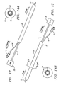
- FIG. 1 depicts an embodiment of an inflatable cannula.
- FIG. 2 is an oblique view of the inflatable cannula.
- FIG. 3 depicts an embodiment of an inflatable cannula having a cardioplegia lumen and port.
- FIG. 4 is an oblique view of the inflatable cannula having the cardioplegia lumen and port.
- FIG. 5 depicts the deflated state of the inflatable cannula.
- FIG. 6 depicts the position of the inflatable cannula deployed within the ascending aorta during cardiac surgery.
- FIG. 7 depicts an embodiment of an inflatable cannula in a deflated state.
- FIG. 8 is a cross-section taken through line 8 — 8 of FIG. 7 .
- FIG. 9 depicts the inflatable cannula of FIG. 7 in an inflated state.
- FIG. 10 is a cross-section taken through line 10 — 10 of FIG. 9 .
- FIG. 11 depicts another embodiment of an inflatable cannula.
- FIG. 12 is a perspective view of an embodiment of an inflatable cannula from the distal end of the cannula.
- FIG. 13 is a perspective view of the inflatable cannula depicted in FIG. 12 from the proximal end of the cannula.
- FIG. 14A is a cross-section taken along lines 14 — 14 of FIG. 13 .
- FIG. 14B is a cross-section taken along lines 14 — 14 of FIG. 13, showing an alternative embodiment of the inflatable cannula depicted in FIG. 13 .
- the devices and methods of the invention facilitate cannulation of the aorta through a minimally invasive port access incision during minimally invasive CABG surgery.
- the invention facilitates thorascopic and/or endovascular delivery of cardioplegic fluid to the myocardium so as to paralyze the heart.
- the invention also provides devices and methods to accommodate large flow of oxygenated blood during cardiopulmonary bypass without need for peripheral access.
- CABG coronary artery bypass grafting
- heart valve repair and replacement
- septal defect repair removal of atrial myxoma
- patent foramen ovale closure treatment of aneurysms
- myocardial drilling electrophysiological mapping and ablation
- correction of congenital defects including coronary artery bypass grafting (CABG), heart valve repair, and replacement, septal defect repair, removal of atrial myxoma, patent foramen ovale closure, treatment of aneurysms, myocardial drilling, electrophysiological mapping and ablation, and correction of congenital defects.
- CABG coronary artery bypass grafting
- septal defect repair removal of atrial myxoma
- patent foramen ovale closure treatment of aneurysms
- myocardial drilling myocardial drilling
- electrophysiological mapping and ablation electrophysiological mapping and ablation
- FIG. 1 depicts an embodiment of an inflatable cannula.
- the cannula has a proximal region 1 , intermediate region 2 , and a distal region 3 .
- the proximal region 1 has tube 6 comprising a fixed lumen 8 .
- Inflation ports 4 and 5 arise from the junction of the proximal and intermediate region.
- Inflation port 4 is responsible for inflating the balloon occluder.
- Inflation port 5 is responsible for inflating the cylindrical balloon.
- Intermediate region 2 comprises the inflatable cylindrical balloon 10 , expandable cannula 18 with lumen 9 , and balloon occluder lumen 15 .
- FIG. 2 depicts an oblique view of the inflatable cannula.
- Distal region 3 includes an angulated lumen port 12 for delivery of blood products and other instruments, and the balloon occluder 13 with its communicating inflation lumen 15 .
- Helical threads 14 are located on the distal cannula close to the junction of the intermediate region.
- FIG. 3 depicts an embodiment of an inflatable cannula having an optional cardioplegia lumen 7 and cardioplegia ports 11 at the distal end.
- FIG. 4 depicts an oblique view of an inflatable cannula having cardioplegia lumen 7 and cardioplegia port 11 at the distal end thereof.
- FIG. 5 depicts an inflatable cannula in the deflated condition. As can be seen, deflation of cylindrical balloon 10 minimizes the cross-sectional diameter of the inflatable cannula for access to a minimal incision port.
- FIG. 6 shows an inflatable cannula deployed within the ascending aorta 17 during cardiac surgery.
- Balloon occluder 13 provides a gentle seal against the aortic wall.
- Blood products or instruments can be delivered through the end port 12 of the cannula downstream to the aorta, while cardioplegia can be delivered through cardioplegia port 11 upstream to the heart.
- FIG. 7 shows an inflatable cannula in the deflated condition.
- the inflatable cannula comprises a proximal region 1 , and a distal region 2 .
- the proximal region includes a tube 6 having a fixed lumen 8 and an inflation port 5 in fluid communication with an inflation lumen 16 .
- the distal region 2 includes a expandable cannula 18 having a lumen 9 , an elongate cylindrical balloon 10 , and space 19 formed between the inner wall of the elongate cylindrical balloon 10 and the outer wall of the expandable cannula 18 .
- the inner wall of the elongate cylindrical balloon 10 is connected at various points to the out wall of the expandable cannula 18 .
- These connections 21 can either be at random points or can be formed in a predetermined pattern.
- the expandable cannula 18 can be made from such materials as Polyethylene Tetraflouride (Teflon®), urethane, nylon, or any other semi-rigid and expandable material or suitable medical grade plastic.
- Teflon® Polyethylene Tetraflouride
- urethane polyurethane
- nylon polyamide
- any other semi-rigid and expandable material or suitable medical grade plastic such materials as Polyethylene Tetraflouride (Teflon®), urethane, nylon, or any other semi-rigid and expandable material or suitable medical grade plastic.
- the fleixble cannula 18 is non-elastic.
- the elongate cylindrical balloon 10 is made of an elastomeric material and is also expandable. It can be made from such materials as silicon, latex, polyurethane, polyimide or any other expandable and elastomeric material. Furthermore, the elongate cylindrical balloon 10 is more flexible and expandable than the expandable cannula 18 .
- the proximal end of the expandable cannula 18 can be connected to or integrally formed with the distal end of the tube 6 so that lumen 8 of the tube 6 and lumen 9 of the expandable cannula 18 are in fluid communication.
- the elongate balloon 10 has openings at its proximal and distal ends. The proximal opening of the elongate cylindrical balloon 10 is sealed around the circumference of the proximal end of the expandable cannula 18 in a fluid-tight manner.
- Inflation lumen 16 is in fluid communication with the space 19 either through an opening on the wall of the elongate cylindrical balloon 10 , or through an opening in the proximal end of the elongate cylindrical balloon 10 , such as an opening in the seal formed between the proximal opening of the balloon 10 and the proximal end of the expandable cannula 18 .
- the proximal end of the elongate cylindrical balloon 10 is sealed in a fluid tight manner around the combination of the inflation lumen 16 and the expandable cannula 18 .
- the distal opening of the elongate cylindrical balloon 10 is sealed around the circumference of the distal end of the expandable cannula 18 in a fluid-tight manner.
- FIG. 8 shows a cross section of the distal region 2 of the inflatable cannula when the cannula is in a deflated condition. It is apparent that the elongate cylindrical balloon 10 is wrapped closely around the expandable cannula 18 , thus compressing the expandable cannula 10 . In this state, the luminal diameter of the expandable cannula 18 is at its minimum value. The diameter of the combination of the expandable cannula 18 and elongate cylindrical balloon 10 is also at its minimum value. The outer wall of the expandable cannula 18 and the inner wall of the elongate balloon 10 are joined at connections 21 , which may be randomly spaced or made in predetermined patterns.
- an elongate cylindrical sleeve (not shown) with little or no expansion properties can be used to compress the combination of the expandable cannula 18 and the elongate cylindrical balloon 10 .
- the sleeve can have a diameter that is smaller than the diameter of the expandable cannula 18 when the expandable cannula 18 is in its expanded state.
- the sleeve can be the length of the expandable cannula 18 or the elongate cylindrical balloon 10 .
- the sleeve is also removable so that when it is removed the elongate cylindrical balloon 10 can be inflated thus expanding the luminal diameter of the expandable cannula 18 , as well as the luminal diameter of the combination of the expandable cannula 18 and the elongate cylindrical balloon 10 .
- an incision is made in the patient, for example, on the aortic wall of the patient.
- the distal end of the inflatable cannula is then inserted through the incision into the aorta.
- the sleeve is then removed by such methods as pulling it proximally until it no longer covers the elongate cylindrical balloon 10 . Alternatively it can be cut off or it can be torn along a perforation along its length.
- the elongate cylindrical balloon 10 can be inflated, thus expanding the luminal diameter of the expandable cannula 18 as well as the luminal diameter of the combination of the expandable cannula 18 and the elongate cylindrical balloon 10 .
- FIG. 9 shows the inflatable cannula of FIGS. 7 and 8 in an inflated condition. It is apparent that fluid has been introduced through inflation lumen 16 into space 19 thus expanding the elongate cylindrical balloon 10 . As can be seen, inflation also causes the luminal diameter of the expandable cannula 18 to increase. Consequently, the diameter of the combination of the expandable cannula 18 and the elongate cylindrical balloon 10 also increases. This increase in the diameter of the combination allows for displacement of tissue when the distal region is inserted through an incision.
- FIG. 10 shows a cross-section of the distal region 2 when the elongate cylindrical balloon is inflated.
- the luminal diameter of the expandable cannula 18 is increased, allowing for passage of blood products and medical instruments.
- the luminal diameter of the combination of the expandable cannula 18 and the elongate cylindrical balloon 10 is also increased, allowing for displacement of tissue.
- FIG. 11 shows an inflatable cannula having an elongate cylindrical balloon 10 disposed about a flexible region of the cannula 18 , as well as a balloon occluder inflation lumen 15 , wherein the elongate cylindrical balloon 10 is shown in its inflated condition.
- the elongate cylindrical balloon 10 covers almost the entire length of the expandable cannula 18 and balloon occluder inflation lumen 15 , including the curved distal region 3 .
- the balloon occluder 13 is circumferentially disposed around the elongate cylindrical balloon 10 .
- the elongate cylindrical balloon 10 has an opening 20 on its distal end through which the balloon occluder inflation lumen 15 is fitted.
- the opening 20 can be sealed in a fluid-tight manner around the outer wall of the balloon occluder inflation lumen 15 so that when fluid is introduced into the elongate cylindrical balloon 10 , it does not leak through the opening and into the balloon occluder 13 . Meanwhile, the proximal and distal openings of the balloon occluder 13 can be sealed in a fluid-tight manner around the outer wall of the elongate cylindrical balloon 10 .
- the elongate cylindrical balloon 10 can be made of different materials along its length.
- the elongate cylindrical balloon 10 can be made of an elostomeric material such as latex, while the section surrounded by the balloon occluder 13 can be made of a less elostomeric and more rigid material such as polyethylene tetraflouride, urethane, nylon, or any medical grade semi-rigid and expandable plastic.
- the expandable cannula 18 is surrounded by an elongate cylindrical balloon 25 , which is toroidal in shape.
- the elongate cylindrical balloon 25 and expandable cannula 18 are shown in an inflated state. In their original state, the balloon 25 is not inflated and is used to compress the expandable cannula 18 .
- a removable elongate cylindrical sleeve can be used to compress the combination of the balloon 25 and the expandable cannula 18 .
- the elongate cylindrical balloon 25 forms a lumen running along the length of the balloon 25 with openings at its proximal and distal ends.
- This embodiment of the inflatable cannula can be made by inserting the expandable cannula 18 through the lumen of the balloon 25 , so that the distal end of the expandable cannula 18 is protruding through the distal opening of the lumen of the balloon 25 , and the proximal end of the expandable cannula 18 extends proximally from the proximal opening of the lumen of the balloon 25 .
- the outer wall of the expandable cannula 18 can be sealed along its length to the lumen of the balloon 25 .
- FIG. 14A shows a cross-section of the expandable lumen cannula with a complete seal 23 formed between the outer wall of the expandable cannula 18 and the lumen of the balloon 25 .
- the outer wall of the expandable cannula 18 can be glued or otherwise connected in any manner at predetermined points to the lumen of the balloon 25 .
- FIG. 14B shows the connections 28 formed between the outer wall of the expandable cannula 18 and the lumen of the balloon 25 . These can be randomly formed along the length of the lumen of the balloon 25 .
- the lumen of the balloon 25 can be connected to the outer wall of the expandable cannula 18 in a known pattern, such as the formation of a series of connecting rings (not shown) at predetermined intervals along the length of the lumen of the balloon 25 .
- Inflation of the balloon 25 causes it to expand, exerting an outward expanding force, thus causing the expandable cannula 18 to expand and to increase in diameter.
- FIG. 13 shows the opening 26 to which the inflation lumen 16 is sealed in a fluid-tight manner.
- the elongate cylindrical balloon 25 can be inflated by introducing fluid through the opening 26 , thus expanding the luminal diameter of the balloon 25 and the luminal diameter of the expandable cannula 18 , as well as expanding the luminal diameter of the combination of the expandable cannula 18 and the balloon 25 .
- the length of region 2 will generally be between 10-20 centimeters, more preferably between 12 and 15 centimeters, with a tube O. D. between 0.3 and 2.0 centimeters, more preferably 0.4-1.0 centimeters, more preferably 0.5-0.7 centimeters, more preferably approximately 0.6 centimeters.
- the cannula will have a circular cross-section. In other embodiments, the cannula will have an oval cross-sectional shape to more easily fit through the ribs, or it may have any other suitable shape.
- the inner diameter of lumen 9 when expanded, will generally be between 0.2 and 2.0 centimeters, more preferably 0.3-1.0 centimeters, more preferably 0.4-0.8 centimeters.
- proximal region 1 will generally be between 2 and 10 centimeters, more preferably about 5 centimeters.
- the tube diameter and proximal region 1 is generally 0.3-1.0 centimeters, while the diameter of lumen 8 in proximal region 1 is about 0.2-0.8 centimeters.
- the balloon occluder In curved distal region 3 , when expanded, the balloon occluder will generally have a diameter between 1 centimeter and 2.5 centimeters, more preferably between 1.5 and 2.0 centimeters.
- the inflatable cannula disclosed herein will be used to perform any of the procedures including coronary artery bypass surgery, valve repair, septal defect repair, and thoracic aortic aneurysm (TAA) repair.
- a typical coronary artery bypass surgery (CABG) using minimally invasive procedures and the cannula disclosed herein generally begins with incubation of the patient after induction of anesthesia as explained in Reichenspurner et al., Annals of Thoracic Surgery 65:413-419 (1998), incorporated herein by reference.
- the right internal jugular vein is punctured using a 9 French introduction system for later insertion of the endopulmonary vent catheter. The patient is placed in a supine position.
- LIMA left internal mammary artery
- Thorascopic preparation of the LIMA is also accomplished through three small lateral chest ports.
- the inflatable cannula can then assist in the above endoscopic dissection of LIMA by its ability to accommodate instruments through its expandable lumen.
- a 21 French venous cannula is inserted into the femoral vein and positioned into the right atrium using transesophageal echocardiography (TEE).
- the inflatable cannula Before the initiation of cardiopulmonary bypass (CPB), the inflatable cannula, in its deflated state, can be inserted through a small port and guided into the ascending aorta using thoroscopy and TEE.
- a Swan-Ganz catheter for pressure monitoring is often inserted through the right internal jugular vein.
- the elongate cylindrical balloon 10 in its deflated state will exert a compressive force against the expandable cannula 18 , allowing for insertion of the inflatable cannula through a small incision.
- the elongate cylindrical balloon 10 and expandable cannula 18 can be covered with a elongate cylindrical sleeve (not shown), which applies a compressive force on both the balloon 10 and the cannula 18 to reduce the luminal diameter of the cannula in its deflated state.
- a elongate cylindrical sleeve (not shown), which applies a compressive force on both the balloon 10 and the cannula 18 to reduce the luminal diameter of the cannula in its deflated state.
- CPB is initiated and the balloon occluder 13 is inflated with approximately 15-30 cc of diluted radiological contrast medium using fluoroscopy and TEE.
- the balloon occluder 13 is generally placed about 2 centimeters above the aortic valve with careful monitoring of the right radial artery pressure to avoid occlusion of the brachiocephalic trunk by the endo-aortic balloon.
- the cylindrical balloon 10 is then inflated by introducing fluid into the space formed between the outer wall of the expandable cannula 18 and the inner wall of the cylindrical balloon 10 .
- the introduction of fluid causes the balloon 10 to expand, thus exerting an outward expanding force on the outer wall of the expandable cannula 18 through connections 21 . Therefore, inflation causes the luminal diameter of the expandable cannula 18 to increase, thereby allowing for free passage of oxygenated blood for CPB.
- Inflation also causes the cylindrical balloon 10 to expand thereby displacing adjacent tissues and organs.
- cardioplegia can be administered through the optional cardioplegia port at the distal region of the inflatable cannula.
- an end-to-end anastomosis is performed of the LIMA to the left anterior descending coronary artery (LAD).
- LAD left anterior descending coronary artery
- the balloon occluder and the cylindrical balloon are deflated, and the cannula is removed.
- the heart is reperfused and the patient is weaned from CPB.
- the femoral cannula is removed, one chest tube is inserted, and the thoracic and femoral incisions are closed.
- Similar steps as described above for minimally invasive CABG can be employed in aortic or mitral valvular replacement.
- the inflatable cannula is inserted through a small chest port to reach the ascending aorta.
- the cylindrical balloon 10 is inflated to expand the luminal diameter of the expandable cannula 18 to accommodate large flow of oxygenated blood from the CPB machine.
- the damaged aortic or mitral valve can be excised and a prosthetic or porcine valve can then be sutured in place.
- the balloon occluder 13 and the cylindrical balloon 10 are deflated and removed. The patient is weaned from CPB, a chest tube is placed, and the femoral and chest incisions are closed.
- Atrial septal defect ASD
- ventricular septal defect VSD
- the inflatable cannula is inserted through a small chest port to reach the ascending aorta.
- the cylindrical balloon 10 is inflated following inflation of the balloon occluder 13 to provide expanded luminal diameter of the expandable cannula 18 to accommodate large flow of oxygenated blood from the CPB machine.
- cardiac incision is made to expose the ASD or VSD.
- a mesh is sutured securely around the defect, and the incision on the heart is closed.
- the inflatable cannula is removed after the balloon occluder 13 and the cylindrical balloon 10 are deflated. After the patient is weaned from CPB, the chest and femoral incisions are closed.
- the inflatable cannula can also assist in repair of thoracic aortic aneurysm (TAA) by providing an expanded conduit for the oxygenated blood from the CPB machine.
- TAA thoracic aortic aneurysm
- the expandable cannula can be inserted distal to the aneurysm and inflated to provide an expanded lumen.
- the diseased aneurysmal aorta is resected and replaced with collagen saturated DacronTM graft.
- the balloons on the cannula are then deflated and the cannula is withdrawn after the patient is weaned from CPB.
- CPB In various pediatric cardiac surgeries, such as ASD, truncous arteriosis, tetralogy of Fallot, anomalous coronary artery, Ebstein's malformation of the tricuspid valve, heart/lung transplantation and total anomalous pulmonary vein repair, CPB is commonly indicated post-operatively due to a low cardiac output state.
- the inflatable cannula can easily be left in place post-operatively to provide easy access to the CPB.
Landscapes
- Health & Medical Sciences (AREA)
- Life Sciences & Earth Sciences (AREA)
- Surgery (AREA)
- Heart & Thoracic Surgery (AREA)
- Animal Behavior & Ethology (AREA)
- Veterinary Medicine (AREA)
- Engineering & Computer Science (AREA)
- Public Health (AREA)
- Biomedical Technology (AREA)
- General Health & Medical Sciences (AREA)
- Vascular Medicine (AREA)
- Reproductive Health (AREA)
- Nuclear Medicine, Radiotherapy & Molecular Imaging (AREA)
- Medical Informatics (AREA)
- Molecular Biology (AREA)
- Hematology (AREA)
- Anesthesiology (AREA)
- Pulmonology (AREA)
- Biophysics (AREA)
- Child & Adolescent Psychology (AREA)
- Surgical Instruments (AREA)
- Media Introduction/Drainage Providing Device (AREA)
Abstract
Description
Claims (13)
Priority Applications (2)
| Application Number | Priority Date | Filing Date | Title |
|---|---|---|---|
| US09/751,445 US6679871B2 (en) | 1998-08-07 | 2000-12-29 | Inflatable cannula and method of using same |
| US10/745,724 US20040138614A1 (en) | 1998-08-07 | 2003-12-23 | Inflatable cannula |
Applications Claiming Priority (2)
| Application Number | Priority Date | Filing Date | Title |
|---|---|---|---|
| US09/130,585 US6168586B1 (en) | 1998-08-07 | 1998-08-07 | Inflatable cannula and method of using same |
| US09/751,445 US6679871B2 (en) | 1998-08-07 | 2000-12-29 | Inflatable cannula and method of using same |
Related Parent Applications (1)
| Application Number | Title | Priority Date | Filing Date |
|---|---|---|---|
| US09/130,585 Continuation-In-Part US6168586B1 (en) | 1998-08-07 | 1998-08-07 | Inflatable cannula and method of using same |
Related Child Applications (1)
| Application Number | Title | Priority Date | Filing Date |
|---|---|---|---|
| US10/745,724 Division US20040138614A1 (en) | 1998-08-07 | 2003-12-23 | Inflatable cannula |
Publications (2)
| Publication Number | Publication Date |
|---|---|
| US20010023332A1 US20010023332A1 (en) | 2001-09-20 |
| US6679871B2 true US6679871B2 (en) | 2004-01-20 |
Family
ID=22445375
Family Applications (3)
| Application Number | Title | Priority Date | Filing Date |
|---|---|---|---|
| US09/130,585 Expired - Lifetime US6168586B1 (en) | 1998-08-07 | 1998-08-07 | Inflatable cannula and method of using same |
| US09/751,445 Expired - Lifetime US6679871B2 (en) | 1998-08-07 | 2000-12-29 | Inflatable cannula and method of using same |
| US10/745,724 Abandoned US20040138614A1 (en) | 1998-08-07 | 2003-12-23 | Inflatable cannula |
Family Applications Before (1)
| Application Number | Title | Priority Date | Filing Date |
|---|---|---|---|
| US09/130,585 Expired - Lifetime US6168586B1 (en) | 1998-08-07 | 1998-08-07 | Inflatable cannula and method of using same |
Family Applications After (1)
| Application Number | Title | Priority Date | Filing Date |
|---|---|---|---|
| US10/745,724 Abandoned US20040138614A1 (en) | 1998-08-07 | 2003-12-23 | Inflatable cannula |
Country Status (3)
| Country | Link |
|---|---|
| US (3) | US6168586B1 (en) |
| AU (1) | AU5326299A (en) |
| WO (1) | WO2000007654A1 (en) |
Cited By (62)
| Publication number | Priority date | Publication date | Assignee | Title |
|---|---|---|---|---|
| US20040138614A1 (en) * | 1998-08-07 | 2004-07-15 | Edwards Lifesciences Corp. | Inflatable cannula |
| US20050107738A1 (en) * | 2000-07-21 | 2005-05-19 | Slater Charles R. | Occludable intravascular catheter for drug delivery and method of using the same |
| US20050203617A1 (en) * | 2004-02-27 | 2005-09-15 | Cardiacmd, Inc. | Prosthetic heart valves, scaffolding structures, and systems and methods for implantation of same |
| US20050230252A1 (en) * | 2004-02-23 | 2005-10-20 | Tsai Fu H | Microfluidic test device |
| US20050251094A1 (en) * | 2003-01-27 | 2005-11-10 | Cardiac Pacemakers, Inc. | System and method for accessing the coronary sinus to facilitate insertion of pacing leads |
| US20070073387A1 (en) * | 2004-02-27 | 2007-03-29 | Forster David C | Prosthetic Heart Valves, Support Structures And Systems And Methods For Implanting The Same |
| US20070129751A1 (en) * | 2004-04-21 | 2007-06-07 | Acclarent, Inc. | Devices, systems and methods useable for treating frontal sinusitis |
| US20070135789A1 (en) * | 2004-04-21 | 2007-06-14 | Acclarent, Inc. | Use of mechanical dilator devices to enlarge ostia of paranasal sinuses and other passages in the ear, nose, throat and paranasal sinuses |
| US20070203575A1 (en) * | 2006-02-27 | 2007-08-30 | Cardiacmd, Inc., A California Corporation | Methods and devices for delivery of prosthetic heart valves and other prosthetics |
| US20070203560A1 (en) * | 2006-02-27 | 2007-08-30 | Cardiacmd, Inc., A California Corporation | Methods and devices for delivery of prosthetic heart valves and other prosthetics |
| US20080009746A1 (en) * | 2006-05-24 | 2008-01-10 | Aortx, Inc., A California Corporation | Assessment of aortic heart valve to facilitate repair or replacement |
| US20080188806A1 (en) * | 2006-09-01 | 2008-08-07 | Giorgio Cattaneo | Device for cannulation of a hollow organ |
| US20080195041A1 (en) * | 2004-04-21 | 2008-08-14 | Acclarent, Inc. | Systems and methods for transnasal dilation of passageways in the ear, nose and throat |
| DE102007037050A1 (en) | 2007-07-24 | 2009-01-29 | Novalung Gmbh | Cannula introducing device for use in extracorporeal circulation system, has expandable structure that is transferred from non-expandable condition into expandable condition by dilator, where structure has opening in expandable condition |
| US20090099554A1 (en) * | 2006-06-20 | 2009-04-16 | Forster David C | Elongate Flexible Torque Instruments And Methods Of Use |
| US20090132035A1 (en) * | 2004-02-27 | 2009-05-21 | Roth Alex T | Prosthetic Heart Valves, Support Structures and Systems and Methods for Implanting the Same |
| US20090187133A1 (en) * | 2002-12-23 | 2009-07-23 | Novalung Gmbh | Appliance for cannulation of a blood vessel |
| US20090187098A1 (en) * | 2004-04-21 | 2009-07-23 | Acclarent, Inc. | Devices, Systems and Methods for Diagnosing and Treating Sinusitis and Other Disorders of the Ears, Nose, and/or Throat |
| US20090209955A1 (en) * | 2006-06-20 | 2009-08-20 | Forster David C | Prosthetic valve implant site preparation techniques |
| US20090210052A1 (en) * | 2006-06-20 | 2009-08-20 | Forster David C | Prosthetic heart valves, support structures and systems and methods for implanting same |
| US20090228098A1 (en) * | 2006-06-21 | 2009-09-10 | Forster David C | Prosthetic valve implantation systems |
| US20090287183A1 (en) * | 2008-05-14 | 2009-11-19 | Onset Medical Corporation | Expandable transapical sheath and method of use |
| US20090318898A1 (en) * | 2008-06-16 | 2009-12-24 | John Richard Dein | Variable diameter surgical drains and sheaths |
| US20100256752A1 (en) * | 2006-09-06 | 2010-10-07 | Forster David C | Prosthetic heart valves, support structures and systems and methods for implanting the same, |
| US20110144583A1 (en) * | 2009-06-08 | 2011-06-16 | Trireme Medical, Inc. | Side branch balloon |
| US20110152763A1 (en) * | 2008-05-14 | 2011-06-23 | Onset Medical Corporation | Expandable iliac sheath and method of use |
| US8728153B2 (en) | 2008-05-14 | 2014-05-20 | Onset Medical Corporation | Expandable transapical sheath and method of use |
| US8764709B2 (en) | 2004-04-21 | 2014-07-01 | Acclarent, Inc. | Devices, systems and methods for treating disorders of the ear, nose and throat |
| US8764786B2 (en) | 2002-09-30 | 2014-07-01 | Acclarent, Inc. | Balloon catheters and methods for treating paranasal sinuses |
| US8777926B2 (en) | 2004-04-21 | 2014-07-15 | Acclarent, Inc. | Apparatus and methods for dilating and modifying ostia of paranasal sinuses and other intranasel or paranasal structures |
| US8905922B2 (en) | 2004-04-21 | 2014-12-09 | Acclarent, Inc. | Devices, systems and methods for diagnosing and treating sinusitis and other disorders of the ears, nose and/or throat |
| US8968269B2 (en) | 2005-09-23 | 2015-03-03 | Acclarent, Inc. | Multi-conduit balloon catheter |
| US9010326B2 (en) | 2012-08-02 | 2015-04-21 | Covidien Lp | Compressible connector for an inner cannula |
| US9072626B2 (en) | 2009-03-31 | 2015-07-07 | Acclarent, Inc. | System and method for treatment of non-ventilating middle ear by providing a gas pathway through the nasopharynx |
| US9084876B2 (en) | 2004-08-04 | 2015-07-21 | Acclarent, Inc. | Implantable devices and methods for delivering drugs and other substances to treat sinusitis and other disorders |
| US9198736B2 (en) | 2006-05-17 | 2015-12-01 | Acclarent, Inc. | Adapter for attaching electromagnetic image guidance components to a medical device |
| US9265906B2 (en) | 2013-02-25 | 2016-02-23 | Covidien Lp | Compressible cannula connector with release grip |
| US9308361B2 (en) | 2005-01-18 | 2016-04-12 | Acclarent, Inc. | Implantable devices and methods for treating sinusitis and other disorders |
| US9433437B2 (en) | 2013-03-15 | 2016-09-06 | Acclarent, Inc. | Apparatus and method for treatment of ethmoid sinusitis |
| US9463068B2 (en) | 2007-05-08 | 2016-10-11 | Acclarent, Inc. | Methods and devices for protecting nasal turbinates |
| US9468362B2 (en) | 2004-04-21 | 2016-10-18 | Acclarent, Inc. | Endoscopic methods and devices for transnasal procedures |
| US9572480B2 (en) | 2006-09-15 | 2017-02-21 | Acclarent, Inc. | Methods and devices for facilitating visualization in a surgical environment |
| US9629684B2 (en) | 2013-03-15 | 2017-04-25 | Acclarent, Inc. | Apparatus and method for treatment of ethmoid sinusitis |
| US9636258B2 (en) | 2009-03-31 | 2017-05-02 | Acclarent, Inc. | System and method for treatment of non-ventilating middle ear by providing a gas pathway through the nasopharynx |
| US9649477B2 (en) | 2004-04-21 | 2017-05-16 | Acclarent, Inc. | Frontal sinus spacer |
| US9750401B2 (en) | 2008-07-30 | 2017-09-05 | Acclarent, Inc. | Paranasal ostium finder devices and methods |
| US9820688B2 (en) | 2006-09-15 | 2017-11-21 | Acclarent, Inc. | Sinus illumination lightwire device |
| US9826999B2 (en) | 2004-04-21 | 2017-11-28 | Acclarent, Inc. | Methods and apparatus for treating disorders of the ear nose and throat |
| US9861793B2 (en) | 2008-03-10 | 2018-01-09 | Acclarent, Inc. | Corewire design and construction for medical devices |
| US9907921B2 (en) | 2013-11-14 | 2018-03-06 | Covidien Lp | Tracheostomy tube with inner cannula |
| US9956383B2 (en) | 2013-03-15 | 2018-05-01 | Cook Medical Technologies Llc | Medical devices and methods for providing access to a bodily passage during dilation |
| US10098652B2 (en) | 2004-04-21 | 2018-10-16 | Acclarent, Inc. | Systems and methods for transnasal dilation of passageways in the ear, nose or throat |
| US10124154B2 (en) | 2005-06-10 | 2018-11-13 | Acclarent, Inc. | Catheters with non-removable guide members useable for treatment of sinusitis |
| US10206821B2 (en) | 2007-12-20 | 2019-02-19 | Acclarent, Inc. | Eustachian tube dilation balloon with ventilation path |
| US10524814B2 (en) | 2009-03-20 | 2020-01-07 | Acclarent, Inc. | Guide system with suction |
| US10631756B2 (en) | 2004-04-21 | 2020-04-28 | Acclarent, Inc. | Guidewires for performing image guided procedures |
| US10702678B2 (en) | 2013-10-14 | 2020-07-07 | Gerstner Medical, Llc | Multiple balloon venous occlusion catheter |
| US10856727B2 (en) | 2004-04-21 | 2020-12-08 | Acclarent, Inc. | Endoscopic methods and devices for transnasal procedures |
| US11019989B2 (en) | 2004-04-21 | 2021-06-01 | Acclarent, Inc. | Methods and apparatus for treating disorders of the ear nose and throat |
| US11020136B2 (en) | 2004-04-21 | 2021-06-01 | Acclarent, Inc. | Deflectable guide catheters and related methods |
| US11202644B2 (en) | 2004-04-21 | 2021-12-21 | Acclarent, Inc. | Shapeable guide catheters and related methods |
| US11529502B2 (en) | 2004-04-21 | 2022-12-20 | Acclarent, Inc. | Apparatus and methods for dilating and modifying ostia of paranasal sinuses and other intranasal or paranasal structures |
Families Citing this family (60)
| Publication number | Priority date | Publication date | Assignee | Title |
|---|---|---|---|---|
| US6129713A (en) * | 1998-08-11 | 2000-10-10 | Embol-X, Inc. | Slidable cannula and method of use |
| US6811546B1 (en) * | 2000-08-25 | 2004-11-02 | Origin Medsystems, Inc. | Endoscopic surgical access port and method |
| DE10105592A1 (en) | 2001-02-06 | 2002-08-08 | Achim Goepferich | Placeholder for drug release in the frontal sinus |
| US7288105B2 (en) | 2001-08-01 | 2007-10-30 | Ev3 Endovascular, Inc. | Tissue opening occluder |
| US6942672B2 (en) | 2001-10-23 | 2005-09-13 | Vascor, Inc. | Method and apparatus for attaching a conduit to the heart or a blood vessel |
| US7883538B2 (en) | 2002-06-13 | 2011-02-08 | Guided Delivery Systems Inc. | Methods and devices for termination |
| EP1530441B1 (en) | 2002-06-13 | 2017-08-02 | Ancora Heart, Inc. | Devices and methods for heart valve repair |
| US8287555B2 (en) | 2003-02-06 | 2012-10-16 | Guided Delivery Systems, Inc. | Devices and methods for heart valve repair |
| US7753858B2 (en) | 2002-06-13 | 2010-07-13 | Guided Delivery Systems, Inc. | Delivery devices and methods for heart valve repair |
| US7753924B2 (en) | 2003-09-04 | 2010-07-13 | Guided Delivery Systems, Inc. | Delivery devices and methods for heart valve repair |
| US7666193B2 (en) | 2002-06-13 | 2010-02-23 | Guided Delivery Sytems, Inc. | Delivery devices and methods for heart valve repair |
| US20060122633A1 (en) | 2002-06-13 | 2006-06-08 | John To | Methods and devices for termination |
| US8641727B2 (en) | 2002-06-13 | 2014-02-04 | Guided Delivery Systems, Inc. | Devices and methods for heart valve repair |
| US9949829B2 (en) | 2002-06-13 | 2018-04-24 | Ancora Heart, Inc. | Delivery devices and methods for heart valve repair |
| US7753922B2 (en) | 2003-09-04 | 2010-07-13 | Guided Delivery Systems, Inc. | Devices and methods for cardiac annulus stabilization and treatment |
| US7758637B2 (en) | 2003-02-06 | 2010-07-20 | Guided Delivery Systems, Inc. | Delivery devices and methods for heart valve repair |
| US7780700B2 (en) | 2003-02-04 | 2010-08-24 | ev3 Endovascular, Inc | Patent foramen ovale closure system |
| US7534204B2 (en) * | 2003-09-03 | 2009-05-19 | Guided Delivery Systems, Inc. | Cardiac visualization devices and methods |
| US7727228B2 (en) * | 2004-03-23 | 2010-06-01 | Medtronic Cryocath Lp | Method and apparatus for inflating and deflating balloon catheters |
| US8491636B2 (en) * | 2004-03-23 | 2013-07-23 | Medtronic Cryopath LP | Method and apparatus for inflating and deflating balloon catheters |
| US9555223B2 (en) | 2004-03-23 | 2017-01-31 | Medtronic Cryocath Lp | Method and apparatus for inflating and deflating balloon catheters |
| US8146400B2 (en) | 2004-04-21 | 2012-04-03 | Acclarent, Inc. | Endoscopic methods and devices for transnasal procedures |
| US9089258B2 (en) | 2004-04-21 | 2015-07-28 | Acclarent, Inc. | Endoscopic methods and devices for transnasal procedures |
| US9351750B2 (en) | 2004-04-21 | 2016-05-31 | Acclarent, Inc. | Devices and methods for treating maxillary sinus disease |
| US7410480B2 (en) | 2004-04-21 | 2008-08-12 | Acclarent, Inc. | Devices and methods for delivering therapeutic substances for the treatment of sinusitis and other disorders |
| US20070179518A1 (en) * | 2006-02-02 | 2007-08-02 | Becker Bruce B | Balloon Catheters and Methods for Treating Paranasal Sinuses |
| US9375217B2 (en) * | 2006-07-18 | 2016-06-28 | Boston Scientific Scimed, Inc. | Catheterizing body lumens |
| US8439687B1 (en) | 2006-12-29 | 2013-05-14 | Acclarent, Inc. | Apparatus and method for simulated insertion and positioning of guidewares and other interventional devices |
| WO2008124567A1 (en) * | 2007-04-05 | 2008-10-16 | Edwards Lifesciences Corporation | Vascular thrombus extractor and extraction method |
| WO2008124787A2 (en) | 2007-04-09 | 2008-10-16 | Acclarent, Inc. | Ethmoidotomy system and implantable spacer devices having therapeutic substance delivery capability for treatment of paranasal sinusitis |
| US8118757B2 (en) | 2007-04-30 | 2012-02-21 | Acclarent, Inc. | Methods and devices for ostium measurement |
| EP2249711B1 (en) | 2008-02-06 | 2021-10-06 | Ancora Heart, Inc. | Multi-window guide tunnel |
| JP2012505048A (en) | 2008-10-10 | 2012-03-01 | ガイデッド デリバリー システムズ, インコーポレイテッド | Termination device and related methods |
| EP2349020B1 (en) | 2008-10-10 | 2020-06-03 | Ancora Heart, Inc. | Tether tensioning device |
| WO2010085456A1 (en) | 2009-01-20 | 2010-07-29 | Guided Delivery Systems Inc. | Anchor deployment devices and related methods |
| WO2011146085A1 (en) * | 2010-05-17 | 2011-11-24 | Numed, Inc. | Rapid response balloon catheter |
| WO2011156176A1 (en) | 2010-06-08 | 2011-12-15 | Regents Of The University Of Minnesota | Vascular elastance |
| US9861350B2 (en) | 2010-09-03 | 2018-01-09 | Ancora Heart, Inc. | Devices and methods for anchoring tissue |
| US9155492B2 (en) | 2010-09-24 | 2015-10-13 | Acclarent, Inc. | Sinus illumination lightwire device |
| EP2642947B1 (en) | 2010-11-22 | 2019-05-22 | Aria CV, Inc. | System for reducing pulsatile pressure |
| US9855375B2 (en) | 2012-07-10 | 2018-01-02 | Valorisation Recherche Hscm, Limited Partnership | Method and device for infusion of pharmacologic agents and thrombus aspiration in artery |
| US20140135786A1 (en) * | 2012-11-09 | 2014-05-15 | Naris Llc | Medical procedure access kit |
| CN103055409B (en) * | 2013-01-31 | 2014-08-13 | 四川大学华西医院 | Transthoracic puncture aortic cannula applicable to minimally invasive cardiac surgery |
| US9216105B2 (en) | 2013-03-14 | 2015-12-22 | Medicele, Llc. | Rectocele and cystocele device |
| US9072582B2 (en) | 2013-03-14 | 2015-07-07 | Ryan Maaskamp | Rectocele device |
| US10213208B2 (en) | 2014-03-24 | 2019-02-26 | J. Mathieu Massicotte | Toroidal balloon for external or internal compression with unique insertion or removal |
| US8876850B1 (en) | 2014-06-19 | 2014-11-04 | Aria Cv, Inc. | Systems and methods for treating pulmonary hypertension |
| CN104224271B (en) * | 2014-09-11 | 2018-11-23 | 中国人民解放军第三军医大学第二附属医院 | Branchofiberoscope biopsy hemostatic ball cuff pipe |
| CA2978599C (en) | 2015-03-05 | 2022-09-06 | Ancora Heart, Inc. | Devices and methods of visualizing and determining depth of penetration in cardiac tissue |
| EP4074285A1 (en) | 2015-05-12 | 2022-10-19 | Ancora Heart, Inc. | Device for releasing catheters from cardiac structures |
| CN105326531B (en) * | 2015-11-25 | 2018-03-09 | 孙德科 | A kind of channel system of Patients With Cerebral Hemorrhage Accepted Micro-traumatic Treatment |
| WO2018075552A1 (en) | 2016-10-19 | 2018-04-26 | Aria Cv, Inc. | Diffusion resistant implantable devices for reducing pulsatile pressure |
| WO2018094258A1 (en) | 2016-11-18 | 2018-05-24 | Ancora Heart, Inc. | Myocardial implant load sharing device and methods to promote lv function |
| EP3983027A4 (en) * | 2019-06-14 | 2023-10-25 | LCMedical LLC | Intracardiac delivery catheter and method of use |
| EP3998969A4 (en) | 2019-07-15 | 2023-08-02 | Ancora Heart, Inc. | Devices and methods for tether cutting |
| US11141581B2 (en) | 2019-09-06 | 2021-10-12 | Aria Cv, Inc. | Diffusion and infusion resistant implantable devices for reducing pulsatile pressure |
| US11259957B2 (en) | 2019-09-25 | 2022-03-01 | Ryan Maaskamp | Rectocele guide |
| CN111529115A (en) * | 2020-05-19 | 2020-08-14 | 河南中医药大学第一附属医院 | Capsule type coronary artery compression device and manufacturing method of chronic myocardial ischemia animal model |
| ES2926596T3 (en) | 2020-05-28 | 2022-10-27 | Medinice S A | Cannula for minimally invasive percutaneous cannulation of the vena cava |
| WO2024054234A1 (en) * | 2022-09-09 | 2024-03-14 | Bard Peripheral Vascular, Inc. | Coaxial needles and biopsy devices for performing a biopsy |
Citations (13)
| Publication number | Priority date | Publication date | Assignee | Title |
|---|---|---|---|---|
| US4636195A (en) * | 1982-04-02 | 1987-01-13 | Harvey Wolinsky | Method and apparatus for removing arterial constriction |
| US4921483A (en) * | 1985-12-19 | 1990-05-01 | Leocor, Inc. | Angioplasty catheter |
| US5250025A (en) * | 1990-08-15 | 1993-10-05 | Intramed Laboratories | Percutaneous access catheter and method of use |
| US5328471A (en) * | 1990-02-26 | 1994-07-12 | Endoluminal Therapeutics, Inc. | Method and apparatus for treatment of focal disease in hollow tubular organs and other tissue lumens |
| US5419763A (en) | 1994-01-04 | 1995-05-30 | Cortrak Medical, Inc. | Prostatic drug-delivery catheter |
| US5558644A (en) * | 1991-07-16 | 1996-09-24 | Heartport, Inc. | Retrograde delivery catheter and method for inducing cardioplegic arrest |
| US5588961A (en) | 1994-06-14 | 1996-12-31 | Cordis Corporation | Electro-osmotic infusion catheter |
| US5766151A (en) * | 1991-07-16 | 1998-06-16 | Heartport, Inc. | Endovascular system for arresting the heart |
| US5775327A (en) | 1995-06-07 | 1998-07-07 | Cardima, Inc. | Guiding catheter for the coronary sinus |
| US5908407A (en) | 1997-07-25 | 1999-06-01 | Neuroperfusion, Inc. | Retroperfusion catheter apparatus and method |
| US5928192A (en) | 1997-07-24 | 1999-07-27 | Embol-X, Inc. | Arterial aspiration |
| US6143015A (en) * | 1997-05-19 | 2000-11-07 | Cardio Medical Solutions, Inc. | Device and method for partially occluding blood vessels using flow-through balloon |
| US6168586B1 (en) * | 1998-08-07 | 2001-01-02 | Embol-X, Inc. | Inflatable cannula and method of using same |
Family Cites Families (10)
| Publication number | Priority date | Publication date | Assignee | Title |
|---|---|---|---|---|
| US5049132A (en) * | 1990-01-08 | 1991-09-17 | Cordis Corporation | Balloon catheter for delivering therapeutic agents |
| US5447497A (en) * | 1992-08-06 | 1995-09-05 | Scimed Life Systems, Inc | Balloon catheter having nonlinear compliance curve and method of using |
| US5342305A (en) * | 1992-08-13 | 1994-08-30 | Cordis Corporation | Variable distention angioplasty balloon assembly |
| US5704913A (en) * | 1993-02-16 | 1998-01-06 | Boston Scientific Corporation | Dilation catheter and method of treatment therewith |
| WO1994021320A1 (en) * | 1993-03-15 | 1994-09-29 | Advanced Cardiovascular Systems, Inc. | Fluid delivery catheter |
| US5395333A (en) * | 1993-09-01 | 1995-03-07 | Scimed Life Systems, Inc. | Multi-lobed support balloon catheter with perfusion |
| DE59610631D1 (en) * | 1996-11-15 | 2003-09-04 | Schneider Europ Gmbh Buelach | Balloon catheter and stent delivery device |
| US6136011A (en) * | 1998-07-14 | 2000-10-24 | Advanced Cardiovascular Systems, Inc. | Stent delivery system and method of use |
| US6471672B1 (en) * | 1999-11-10 | 2002-10-29 | Scimed Life Systems | Selective high pressure dilation balloon |
| US6626859B2 (en) * | 2000-01-18 | 2003-09-30 | Coraflo Ltd. | High performance cannulas |
-
1998
- 1998-08-07 US US09/130,585 patent/US6168586B1/en not_active Expired - Lifetime
-
1999
- 1999-07-29 WO PCT/US1999/017200 patent/WO2000007654A1/en active Application Filing
- 1999-07-29 AU AU53262/99A patent/AU5326299A/en not_active Abandoned
-
2000
- 2000-12-29 US US09/751,445 patent/US6679871B2/en not_active Expired - Lifetime
-
2003
- 2003-12-23 US US10/745,724 patent/US20040138614A1/en not_active Abandoned
Patent Citations (14)
| Publication number | Priority date | Publication date | Assignee | Title |
|---|---|---|---|---|
| US4636195A (en) * | 1982-04-02 | 1987-01-13 | Harvey Wolinsky | Method and apparatus for removing arterial constriction |
| US4921483A (en) * | 1985-12-19 | 1990-05-01 | Leocor, Inc. | Angioplasty catheter |
| US5328471A (en) * | 1990-02-26 | 1994-07-12 | Endoluminal Therapeutics, Inc. | Method and apparatus for treatment of focal disease in hollow tubular organs and other tissue lumens |
| US5250025A (en) * | 1990-08-15 | 1993-10-05 | Intramed Laboratories | Percutaneous access catheter and method of use |
| US5766151A (en) * | 1991-07-16 | 1998-06-16 | Heartport, Inc. | Endovascular system for arresting the heart |
| US5558644A (en) * | 1991-07-16 | 1996-09-24 | Heartport, Inc. | Retrograde delivery catheter and method for inducing cardioplegic arrest |
| US5419763A (en) | 1994-01-04 | 1995-05-30 | Cortrak Medical, Inc. | Prostatic drug-delivery catheter |
| US5419763B1 (en) | 1994-01-04 | 1997-07-15 | Cor Trak Medical Inc | Prostatic drug-delivery catheter |
| US5588961A (en) | 1994-06-14 | 1996-12-31 | Cordis Corporation | Electro-osmotic infusion catheter |
| US5775327A (en) | 1995-06-07 | 1998-07-07 | Cardima, Inc. | Guiding catheter for the coronary sinus |
| US6143015A (en) * | 1997-05-19 | 2000-11-07 | Cardio Medical Solutions, Inc. | Device and method for partially occluding blood vessels using flow-through balloon |
| US5928192A (en) | 1997-07-24 | 1999-07-27 | Embol-X, Inc. | Arterial aspiration |
| US5908407A (en) | 1997-07-25 | 1999-06-01 | Neuroperfusion, Inc. | Retroperfusion catheter apparatus and method |
| US6168586B1 (en) * | 1998-08-07 | 2001-01-02 | Embol-X, Inc. | Inflatable cannula and method of using same |
Cited By (132)
| Publication number | Priority date | Publication date | Assignee | Title |
|---|---|---|---|---|
| US20040138614A1 (en) * | 1998-08-07 | 2004-07-15 | Edwards Lifesciences Corp. | Inflatable cannula |
| US20050107738A1 (en) * | 2000-07-21 | 2005-05-19 | Slater Charles R. | Occludable intravascular catheter for drug delivery and method of using the same |
| US9457175B2 (en) | 2002-09-30 | 2016-10-04 | Acclarent, Inc. | Balloon catheters and methods for treating paranasal sinuses |
| US8764786B2 (en) | 2002-09-30 | 2014-07-01 | Acclarent, Inc. | Balloon catheters and methods for treating paranasal sinuses |
| US20090187133A1 (en) * | 2002-12-23 | 2009-07-23 | Novalung Gmbh | Appliance for cannulation of a blood vessel |
| US8419671B2 (en) | 2002-12-23 | 2013-04-16 | Novalung Gmbh | Appliance for cannulation of a blood vessel |
| US20050251094A1 (en) * | 2003-01-27 | 2005-11-10 | Cardiac Pacemakers, Inc. | System and method for accessing the coronary sinus to facilitate insertion of pacing leads |
| US7570981B2 (en) * | 2003-01-27 | 2009-08-04 | Cardiac Pacemakers, Inc. | System and method for accessing the coronary sinus to facilitate insertion of pacing leads |
| US20050230252A1 (en) * | 2004-02-23 | 2005-10-20 | Tsai Fu H | Microfluidic test device |
| US8430925B2 (en) | 2004-02-27 | 2013-04-30 | Cardiacmd, Inc. | Prosthetic heart valves, scaffolding structures, and systems and methods for implantation of same |
| US7785341B2 (en) | 2004-02-27 | 2010-08-31 | Aortx, Inc. | Prosthetic heart valves, scaffolding structures, and systems and methods for implantation of same |
| US8728156B2 (en) | 2004-02-27 | 2014-05-20 | Cardiac MD, Inc. | Prosthetic heart valves, scaffolding structures, and systems and methods for implantation of same |
| US8608770B2 (en) | 2004-02-27 | 2013-12-17 | Cardiacmd, Inc. | Prosthetic heart valves, scaffolding structures, and systems and methods for implantation of same |
| US20070073387A1 (en) * | 2004-02-27 | 2007-03-29 | Forster David C | Prosthetic Heart Valves, Support Structures And Systems And Methods For Implanting The Same |
| US20050203615A1 (en) * | 2004-02-27 | 2005-09-15 | Cardiacmd, Inc. | Prosthetic heart valves, scaffolding structures, and systems and methods for implantation of same |
| US8128692B2 (en) | 2004-02-27 | 2012-03-06 | Aortx, Inc. | Prosthetic heart valves, scaffolding structures, and systems and methods for implantation of same |
| US20110082540A1 (en) * | 2004-02-27 | 2011-04-07 | Forster David C | Prosthetic Heart Valves, Scaffolding Structures, and Systems and Methods for Implantation of Same |
| US20090132035A1 (en) * | 2004-02-27 | 2009-05-21 | Roth Alex T | Prosthetic Heart Valves, Support Structures and Systems and Methods for Implanting the Same |
| US20050203617A1 (en) * | 2004-02-27 | 2005-09-15 | Cardiacmd, Inc. | Prosthetic heart valves, scaffolding structures, and systems and methods for implantation of same |
| US20100305691A1 (en) * | 2004-02-27 | 2010-12-02 | Forster David C | Prosthetic Heart Valves, Scaffolding Structures, and Systems and Methods for Implantation of Same |
| US9168134B2 (en) | 2004-02-27 | 2015-10-27 | Cardiacmd, Inc. | Method for delivering a prosthetic heart valve with an expansion member |
| US20100256724A1 (en) * | 2004-02-27 | 2010-10-07 | Forster David C | Prosthetic Heart Valves, Scaffolding Structures, and Systems and Methods for Implantation of Same |
| US9101384B2 (en) | 2004-04-21 | 2015-08-11 | Acclarent, Inc. | Devices, systems and methods for diagnosing and treating sinusitis and other disorders of the ears, Nose and/or throat |
| US10695080B2 (en) | 2004-04-21 | 2020-06-30 | Acclarent, Inc. | Devices, systems and methods for diagnosing and treating sinusitis and other disorders of the ears, nose and/or throat |
| US11957318B2 (en) | 2004-04-21 | 2024-04-16 | Acclarent, Inc. | Methods and apparatus for treating disorders of the ear nose and throat |
| US11864725B2 (en) | 2004-04-21 | 2024-01-09 | Acclarent, Inc. | Devices, systems and methods for diagnosing and treating sinusitis and other disorders of the ears, nose and/or throat |
| US11589742B2 (en) | 2004-04-21 | 2023-02-28 | Acclarent, Inc. | Methods and apparatus for treating disorders of the ear nose and throat |
| US10098652B2 (en) | 2004-04-21 | 2018-10-16 | Acclarent, Inc. | Systems and methods for transnasal dilation of passageways in the ear, nose or throat |
| US10441758B2 (en) | 2004-04-21 | 2019-10-15 | Acclarent, Inc. | Frontal sinus spacer |
| US9826999B2 (en) | 2004-04-21 | 2017-11-28 | Acclarent, Inc. | Methods and apparatus for treating disorders of the ear nose and throat |
| US10492810B2 (en) | 2004-04-21 | 2019-12-03 | Acclarent, Inc. | Devices, systems and methods for diagnosing and treating sinusitis and other disorders of the ears, nose and/or throat |
| US9713700B2 (en) | 2004-04-21 | 2017-07-25 | Acclarent, Inc. | Apparatus and methods for dilating and modifying ostia of paranasal sinuses and other intranasal or paranasal structures |
| US20090187098A1 (en) * | 2004-04-21 | 2009-07-23 | Acclarent, Inc. | Devices, Systems and Methods for Diagnosing and Treating Sinusitis and Other Disorders of the Ears, Nose, and/or Throat |
| US9649477B2 (en) | 2004-04-21 | 2017-05-16 | Acclarent, Inc. | Frontal sinus spacer |
| US11529502B2 (en) | 2004-04-21 | 2022-12-20 | Acclarent, Inc. | Apparatus and methods for dilating and modifying ostia of paranasal sinuses and other intranasal or paranasal structures |
| US11511090B2 (en) | 2004-04-21 | 2022-11-29 | Acclarent, Inc. | Devices, systems and methods useable for treating sinusitis |
| US10500380B2 (en) | 2004-04-21 | 2019-12-10 | Acclarent, Inc. | Devices, systems and methods useable for treating sinusitis |
| US11202644B2 (en) | 2004-04-21 | 2021-12-21 | Acclarent, Inc. | Shapeable guide catheters and related methods |
| US10631756B2 (en) | 2004-04-21 | 2020-04-28 | Acclarent, Inc. | Guidewires for performing image guided procedures |
| US9468362B2 (en) | 2004-04-21 | 2016-10-18 | Acclarent, Inc. | Endoscopic methods and devices for transnasal procedures |
| US20070129751A1 (en) * | 2004-04-21 | 2007-06-07 | Acclarent, Inc. | Devices, systems and methods useable for treating frontal sinusitis |
| US10702295B2 (en) | 2004-04-21 | 2020-07-07 | Acclarent, Inc. | Methods and apparatus for treating disorders of the ear nose and throat |
| US11020136B2 (en) | 2004-04-21 | 2021-06-01 | Acclarent, Inc. | Deflectable guide catheters and related methods |
| US20080195041A1 (en) * | 2004-04-21 | 2008-08-14 | Acclarent, Inc. | Systems and methods for transnasal dilation of passageways in the ear, nose and throat |
| US9370649B2 (en) | 2004-04-21 | 2016-06-21 | Acclarent, Inc. | Devices, systems and methods useable for treating sinusitis |
| US10779752B2 (en) | 2004-04-21 | 2020-09-22 | Acclarent, Inc. | Guidewires for performing image guided procedures |
| US9241834B2 (en) | 2004-04-21 | 2016-01-26 | Acclarent, Inc. | Devices, systems and methods for treating disorders of the ear, nose and throat |
| US11019989B2 (en) | 2004-04-21 | 2021-06-01 | Acclarent, Inc. | Methods and apparatus for treating disorders of the ear nose and throat |
| US9220879B2 (en) | 2004-04-21 | 2015-12-29 | Acclarent, Inc. | Devices, systems and methods useable for treating sinusitis |
| US20070135789A1 (en) * | 2004-04-21 | 2007-06-14 | Acclarent, Inc. | Use of mechanical dilator devices to enlarge ostia of paranasal sinuses and other passages in the ear, nose, throat and paranasal sinuses |
| US10874838B2 (en) | 2004-04-21 | 2020-12-29 | Acclarent, Inc. | Systems and methods for transnasal dilation of passageways in the ear, nose or throat |
| US10856727B2 (en) | 2004-04-21 | 2020-12-08 | Acclarent, Inc. | Endoscopic methods and devices for transnasal procedures |
| US10806477B2 (en) | 2004-04-21 | 2020-10-20 | Acclarent, Inc. | Systems and methods for transnasal dilation of passageways in the ear, nose or throat |
| US8747389B2 (en) | 2004-04-21 | 2014-06-10 | Acclarent, Inc. | Systems for treating disorders of the ear, nose and throat |
| US8764709B2 (en) | 2004-04-21 | 2014-07-01 | Acclarent, Inc. | Devices, systems and methods for treating disorders of the ear, nose and throat |
| US8905922B2 (en) | 2004-04-21 | 2014-12-09 | Acclarent, Inc. | Devices, systems and methods for diagnosing and treating sinusitis and other disorders of the ears, nose and/or throat |
| US8777926B2 (en) | 2004-04-21 | 2014-07-15 | Acclarent, Inc. | Apparatus and methods for dilating and modifying ostia of paranasal sinuses and other intranasel or paranasal structures |
| US8852143B2 (en) | 2004-04-21 | 2014-10-07 | Acclarent, Inc. | Devices, systems and methods for treating disorders of the ear, nose and throat |
| US8858586B2 (en) | 2004-04-21 | 2014-10-14 | Acclarent, Inc. | Methods for enlarging ostia of paranasal sinuses |
| US8894614B2 (en) | 2004-04-21 | 2014-11-25 | Acclarent, Inc. | Devices, systems and methods useable for treating frontal sinusitis |
| US9084876B2 (en) | 2004-08-04 | 2015-07-21 | Acclarent, Inc. | Implantable devices and methods for delivering drugs and other substances to treat sinusitis and other disorders |
| US9308361B2 (en) | 2005-01-18 | 2016-04-12 | Acclarent, Inc. | Implantable devices and methods for treating sinusitis and other disorders |
| US10124154B2 (en) | 2005-06-10 | 2018-11-13 | Acclarent, Inc. | Catheters with non-removable guide members useable for treatment of sinusitis |
| US10842978B2 (en) | 2005-06-10 | 2020-11-24 | Acclarent, Inc. | Catheters with non-removable guide members useable for treatment of sinusitis |
| US8968269B2 (en) | 2005-09-23 | 2015-03-03 | Acclarent, Inc. | Multi-conduit balloon catheter |
| US9999752B2 (en) | 2005-09-23 | 2018-06-19 | Acclarent, Inc. | Multi-conduit balloon catheter |
| US10639457B2 (en) | 2005-09-23 | 2020-05-05 | Acclarent, Inc. | Multi-conduit balloon catheter |
| US20070203561A1 (en) * | 2006-02-27 | 2007-08-30 | Cardiacmd, Inc. A California Corporation | Methods and devices for delivery of prosthetic heart valves and other prosthetics |
| US20070203560A1 (en) * | 2006-02-27 | 2007-08-30 | Cardiacmd, Inc., A California Corporation | Methods and devices for delivery of prosthetic heart valves and other prosthetics |
| US7749266B2 (en) | 2006-02-27 | 2010-07-06 | Aortx, Inc. | Methods and devices for delivery of prosthetic heart valves and other prosthetics |
| US8147541B2 (en) | 2006-02-27 | 2012-04-03 | Aortx, Inc. | Methods and devices for delivery of prosthetic heart valves and other prosthetics |
| US20070203575A1 (en) * | 2006-02-27 | 2007-08-30 | Cardiacmd, Inc., A California Corporation | Methods and devices for delivery of prosthetic heart valves and other prosthetics |
| US8403981B2 (en) | 2006-02-27 | 2013-03-26 | CardiacMC, Inc. | Methods and devices for delivery of prosthetic heart valves and other prosthetics |
| US9198736B2 (en) | 2006-05-17 | 2015-12-01 | Acclarent, Inc. | Adapter for attaching electromagnetic image guidance components to a medical device |
| US9629656B2 (en) | 2006-05-17 | 2017-04-25 | Acclarent, Inc. | Adapter for attaching electromagnetic image guidance components to a medical device |
| US8585594B2 (en) | 2006-05-24 | 2013-11-19 | Phoenix Biomedical, Inc. | Methods of assessing inner surfaces of body lumens or organs |
| US8057396B2 (en) | 2006-05-24 | 2011-11-15 | Phoenix Biomedical, Inc. | Device for assessing a cardiac valve |
| US20080009746A1 (en) * | 2006-05-24 | 2008-01-10 | Aortx, Inc., A California Corporation | Assessment of aortic heart valve to facilitate repair or replacement |
| US20100217119A1 (en) * | 2006-05-24 | 2010-08-26 | Forster David C | Assessment Of Aortic Heart Valve To Facilitate Repair Or Replacement |
| US20090210052A1 (en) * | 2006-06-20 | 2009-08-20 | Forster David C | Prosthetic heart valves, support structures and systems and methods for implanting same |
| US8500799B2 (en) | 2006-06-20 | 2013-08-06 | Cardiacmd, Inc. | Prosthetic heart valves, support structures and systems and methods for implanting same |
| US20090099554A1 (en) * | 2006-06-20 | 2009-04-16 | Forster David C | Elongate Flexible Torque Instruments And Methods Of Use |
| US20090209955A1 (en) * | 2006-06-20 | 2009-08-20 | Forster David C | Prosthetic valve implant site preparation techniques |
| US8376865B2 (en) | 2006-06-20 | 2013-02-19 | Cardiacmd, Inc. | Torque shaft and torque shaft drive |
| US8142492B2 (en) | 2006-06-21 | 2012-03-27 | Aortx, Inc. | Prosthetic valve implantation systems |
| US20090228098A1 (en) * | 2006-06-21 | 2009-09-10 | Forster David C | Prosthetic valve implantation systems |
| US20080188806A1 (en) * | 2006-09-01 | 2008-08-07 | Giorgio Cattaneo | Device for cannulation of a hollow organ |
| US8500689B2 (en) | 2006-09-01 | 2013-08-06 | Novalung Gmbh | Device for cannulation of a hollow organ |
| US20100256752A1 (en) * | 2006-09-06 | 2010-10-07 | Forster David C | Prosthetic heart valves, support structures and systems and methods for implanting the same, |
| US9572480B2 (en) | 2006-09-15 | 2017-02-21 | Acclarent, Inc. | Methods and devices for facilitating visualization in a surgical environment |
| US9820688B2 (en) | 2006-09-15 | 2017-11-21 | Acclarent, Inc. | Sinus illumination lightwire device |
| US10716629B2 (en) | 2006-09-15 | 2020-07-21 | Acclarent, Inc. | Methods and devices for facilitating visualization in a surgical environment |
| US9463068B2 (en) | 2007-05-08 | 2016-10-11 | Acclarent, Inc. | Methods and devices for protecting nasal turbinates |
| DE102007037050A1 (en) | 2007-07-24 | 2009-01-29 | Novalung Gmbh | Cannula introducing device for use in extracorporeal circulation system, has expandable structure that is transferred from non-expandable condition into expandable condition by dilator, where structure has opening in expandable condition |
| US11850120B2 (en) | 2007-12-20 | 2023-12-26 | Acclarent, Inc. | Eustachian tube dilation balloon with ventilation path |
| US11311419B2 (en) | 2007-12-20 | 2022-04-26 | Acclarent, Inc. | Eustachian tube dilation balloon with ventilation path |
| US10206821B2 (en) | 2007-12-20 | 2019-02-19 | Acclarent, Inc. | Eustachian tube dilation balloon with ventilation path |
| US9861793B2 (en) | 2008-03-10 | 2018-01-09 | Acclarent, Inc. | Corewire design and construction for medical devices |
| US20110152763A1 (en) * | 2008-05-14 | 2011-06-23 | Onset Medical Corporation | Expandable iliac sheath and method of use |
| US20090287183A1 (en) * | 2008-05-14 | 2009-11-19 | Onset Medical Corporation | Expandable transapical sheath and method of use |
| US8668668B2 (en) | 2008-05-14 | 2014-03-11 | Onset Medical Corporation | Expandable iliac sheath and method of use |
| US8728153B2 (en) | 2008-05-14 | 2014-05-20 | Onset Medical Corporation | Expandable transapical sheath and method of use |
| US9387314B2 (en) | 2008-05-14 | 2016-07-12 | Onset Medical Corporation | Expandable iliac sheath and method of use |
| US9433766B2 (en) | 2008-05-14 | 2016-09-06 | Onset Medical Corporation | Expandable iliac sheath and method of use |
| US9440054B2 (en) | 2008-05-14 | 2016-09-13 | Onset Medical Corporation | Expandable transapical sheath and method of use |
| US8562559B2 (en) * | 2008-05-14 | 2013-10-22 | Onset Medical Corporation | Expandable iliac sheath and method of use |
| US20090287182A1 (en) * | 2008-05-14 | 2009-11-19 | Onset Medical Corporation | Expandable iliac sheath and method of use |
| US10307574B2 (en) | 2008-06-16 | 2019-06-04 | John R. Dein | Variable diameter surgical drains and sheaths |
| US20090318898A1 (en) * | 2008-06-16 | 2009-12-24 | John Richard Dein | Variable diameter surgical drains and sheaths |
| US8403913B2 (en) | 2008-06-16 | 2013-03-26 | John Richard Dein | Variable diameter surgical drains and sheaths |
| US9750401B2 (en) | 2008-07-30 | 2017-09-05 | Acclarent, Inc. | Paranasal ostium finder devices and methods |
| US11116392B2 (en) | 2008-07-30 | 2021-09-14 | Acclarent, Inc. | Paranasal ostium finder devices and methods |
| US10271719B2 (en) | 2008-07-30 | 2019-04-30 | Acclarent, Inc. | Paranasal ostium finder devices and methods |
| US10524814B2 (en) | 2009-03-20 | 2020-01-07 | Acclarent, Inc. | Guide system with suction |
| US11207087B2 (en) | 2009-03-20 | 2021-12-28 | Acclarent, Inc. | Guide system with suction |
| US9636258B2 (en) | 2009-03-31 | 2017-05-02 | Acclarent, Inc. | System and method for treatment of non-ventilating middle ear by providing a gas pathway through the nasopharynx |
| US9072626B2 (en) | 2009-03-31 | 2015-07-07 | Acclarent, Inc. | System and method for treatment of non-ventilating middle ear by providing a gas pathway through the nasopharynx |
| US10376416B2 (en) | 2009-03-31 | 2019-08-13 | Acclarent, Inc. | System and method for treatment of non-ventilating middle ear by providing a gas pathway through the nasopharynx |
| US10493246B2 (en) | 2009-06-08 | 2019-12-03 | Trireme Medical, Inc. | Side branch balloon |
| US20110144583A1 (en) * | 2009-06-08 | 2011-06-16 | Trireme Medical, Inc. | Side branch balloon |
| US9010326B2 (en) | 2012-08-02 | 2015-04-21 | Covidien Lp | Compressible connector for an inner cannula |
| US11040160B2 (en) | 2012-08-02 | 2021-06-22 | Covidien Lp | Compressible connector for an inner cannula |
| US10130781B2 (en) | 2012-08-02 | 2018-11-20 | Covidien Lp | Compressible connector for an inner cannula |
| US9265906B2 (en) | 2013-02-25 | 2016-02-23 | Covidien Lp | Compressible cannula connector with release grip |
| US10307557B2 (en) | 2013-02-25 | 2019-06-04 | Covidien Lp | Compressible cannula connector with release grip |
| US9629684B2 (en) | 2013-03-15 | 2017-04-25 | Acclarent, Inc. | Apparatus and method for treatment of ethmoid sinusitis |
| US10524869B2 (en) | 2013-03-15 | 2020-01-07 | Acclarent, Inc. | Apparatus and method for treatment of ethmoid sinusitis |
| US9956383B2 (en) | 2013-03-15 | 2018-05-01 | Cook Medical Technologies Llc | Medical devices and methods for providing access to a bodily passage during dilation |
| US9433437B2 (en) | 2013-03-15 | 2016-09-06 | Acclarent, Inc. | Apparatus and method for treatment of ethmoid sinusitis |
| US10702678B2 (en) | 2013-10-14 | 2020-07-07 | Gerstner Medical, Llc | Multiple balloon venous occlusion catheter |
| US11007336B2 (en) | 2013-11-14 | 2021-05-18 | Covidien Lp | Tracheostomy tube with inner cannula |
| US9907921B2 (en) | 2013-11-14 | 2018-03-06 | Covidien Lp | Tracheostomy tube with inner cannula |
Also Published As
| Publication number | Publication date |
|---|---|
| US6168586B1 (en) | 2001-01-02 |
| US20010023332A1 (en) | 2001-09-20 |
| WO2000007654A9 (en) | 2000-10-05 |
| WO2000007654A1 (en) | 2000-02-17 |
| WO2000007654B1 (en) | 2000-03-23 |
| AU5326299A (en) | 2000-02-28 |
| US20040138614A1 (en) | 2004-07-15 |
Similar Documents
| Publication | Publication Date | Title |
|---|---|---|
| US6679871B2 (en) | Inflatable cannula and method of using same | |
| US6352530B1 (en) | Slideable cannula and method of use | |
| US6190357B1 (en) | Expandable cannula for performing cardiopulmonary bypass and method for using same | |
| US6042563A (en) | Methods and apparatus for occluding a blood vessel | |
| US6936057B1 (en) | Device and method for partially occluding blood vessels using flow-through balloon | |
| US6143015A (en) | Device and method for partially occluding blood vessels using flow-through balloon | |
| EP0999790B1 (en) | Temporary vascular seal for anastomosis | |
| US6482214B1 (en) | Intravascular seal with mesh reinforcement and method for using same | |
| US6071297A (en) | Perfusion device for maintaining blood flow in a vessel while isolating an anastomosis | |
| US7351247B2 (en) | Devices and methods for interconnecting body conduits | |
| US6033420A (en) | Trocar introducer system and methods of use | |
| AU760885B2 (en) | Percutaneous filtration catheter for valve repair surgery and methods of use | |
| EP0836501B1 (en) | Endovascular system for arresting the heart | |
| US5980503A (en) | Endoscopic cardioplegia infusion cannula and method of use | |
| US9295818B2 (en) | Method and apparatus for accessing the wall of a vascular structure or other body lumen while simultaneously providing zone isolation and fluid bypass capability | |
| US11957355B2 (en) | Vascular access devices, systems, and methods | |
| JPH08511694A (en) | Thoracoscopic cardiac bypass procedure | |
| JP2000508949A (en) | Endovascular balloon occlusion device and method of use | |
| EP0983027B1 (en) | Device for partially occluding blood vessels | |
| AU2334599A (en) | Methods and devices for occluding the ascending aorta and maintaining circulation of oxygenated blood in the patient when the patient's heart is arrested | |
| WO2000018303A1 (en) | Minimally invasive cardiac surgery procedure | |
| JP2002102260A (en) | Shunt tube inside artery and its using method | |
| US20050203564A1 (en) | Blood vessel occlusion device | |
| WO2020231715A1 (en) | Partial vessel occlusion device |
Legal Events
| Date | Code | Title | Description |
|---|---|---|---|
| AS | Assignment |
Owner name: EDWARDS LIFESCIENCES CORPORATION, CALIFORNIA Free format text: ASSIGNMENT OF ASSIGNORS INTEREST;ASSIGNOR:EMBOL-X, INC.;REEL/FRAME:013998/0632 Effective date: 20030417 |
|
| AS | Assignment |
Owner name: EDWARDS LIFESCIENCES CORPORATION, CALIFORNIA Free format text: ASSIGNMENT OF ASSIGNORS INTEREST;ASSIGNOR:HAHNEN, KEVIN;REEL/FRAME:014684/0547 Effective date: 20031024 |
|
| STCF | Information on status: patent grant |
Free format text: PATENTED CASE |
|
| FPAY | Fee payment |
Year of fee payment: 4 |
|
| FPAY | Fee payment |
Year of fee payment: 8 |
|
| FPAY | Fee payment |
Year of fee payment: 12 |