US6656079B2 - Differential gear and method of making same - Google Patents
Differential gear and method of making same Download PDFInfo
- Publication number
- US6656079B2 US6656079B2 US09/810,528 US81052801A US6656079B2 US 6656079 B2 US6656079 B2 US 6656079B2 US 81052801 A US81052801 A US 81052801A US 6656079 B2 US6656079 B2 US 6656079B2
- Authority
- US
- United States
- Prior art keywords
- differential
- crown wheel
- differential gear
- bearing shoulder
- weld seam
- Prior art date
- Legal status (The legal status is an assumption and is not a legal conclusion. Google has not performed a legal analysis and makes no representation as to the accuracy of the status listed.)
- Expired - Fee Related
Links
Images


Classifications
-
- F—MECHANICAL ENGINEERING; LIGHTING; HEATING; WEAPONS; BLASTING
- F16—ENGINEERING ELEMENTS AND UNITS; GENERAL MEASURES FOR PRODUCING AND MAINTAINING EFFECTIVE FUNCTIONING OF MACHINES OR INSTALLATIONS; THERMAL INSULATION IN GENERAL
- F16H—GEARING
- F16H48/00—Differential gearings
- F16H48/06—Differential gearings with gears having orbital motion
- F16H48/08—Differential gearings with gears having orbital motion comprising bevel gears
-
- B—PERFORMING OPERATIONS; TRANSPORTING
- B23—MACHINE TOOLS; METAL-WORKING NOT OTHERWISE PROVIDED FOR
- B23K—SOLDERING OR UNSOLDERING; WELDING; CLADDING OR PLATING BY SOLDERING OR WELDING; CUTTING BY APPLYING HEAT LOCALLY, e.g. FLAME CUTTING; WORKING BY LASER BEAM
- B23K2103/00—Materials to be soldered, welded or cut
- B23K2103/02—Iron or ferrous alloys
- B23K2103/04—Steel or steel alloys
-
- B—PERFORMING OPERATIONS; TRANSPORTING
- B23—MACHINE TOOLS; METAL-WORKING NOT OTHERWISE PROVIDED FOR
- B23K—SOLDERING OR UNSOLDERING; WELDING; CLADDING OR PLATING BY SOLDERING OR WELDING; CUTTING BY APPLYING HEAT LOCALLY, e.g. FLAME CUTTING; WORKING BY LASER BEAM
- B23K2103/00—Materials to be soldered, welded or cut
- B23K2103/02—Iron or ferrous alloys
- B23K2103/06—Cast-iron alloys
-
- B—PERFORMING OPERATIONS; TRANSPORTING
- B23—MACHINE TOOLS; METAL-WORKING NOT OTHERWISE PROVIDED FOR
- B23K—SOLDERING OR UNSOLDERING; WELDING; CLADDING OR PLATING BY SOLDERING OR WELDING; CUTTING BY APPLYING HEAT LOCALLY, e.g. FLAME CUTTING; WORKING BY LASER BEAM
- B23K2103/00—Materials to be soldered, welded or cut
- B23K2103/18—Dissimilar materials
-
- B—PERFORMING OPERATIONS; TRANSPORTING
- B23—MACHINE TOOLS; METAL-WORKING NOT OTHERWISE PROVIDED FOR
- B23K—SOLDERING OR UNSOLDERING; WELDING; CLADDING OR PLATING BY SOLDERING OR WELDING; CUTTING BY APPLYING HEAT LOCALLY, e.g. FLAME CUTTING; WORKING BY LASER BEAM
- B23K35/00—Rods, electrodes, materials, or media, for use in soldering, welding, or cutting
- B23K35/22—Rods, electrodes, materials, or media, for use in soldering, welding, or cutting characterised by the composition or nature of the material
- B23K35/24—Selection of soldering or welding materials proper
- B23K35/30—Selection of soldering or welding materials proper with the principal constituent melting at less than 1550 degrees C
- B23K35/3033—Ni as the principal constituent
-
- B—PERFORMING OPERATIONS; TRANSPORTING
- B23—MACHINE TOOLS; METAL-WORKING NOT OTHERWISE PROVIDED FOR
- B23K—SOLDERING OR UNSOLDERING; WELDING; CLADDING OR PLATING BY SOLDERING OR WELDING; CUTTING BY APPLYING HEAT LOCALLY, e.g. FLAME CUTTING; WORKING BY LASER BEAM
- B23K35/00—Rods, electrodes, materials, or media, for use in soldering, welding, or cutting
- B23K35/22—Rods, electrodes, materials, or media, for use in soldering, welding, or cutting characterised by the composition or nature of the material
- B23K35/24—Selection of soldering or welding materials proper
- B23K35/30—Selection of soldering or welding materials proper with the principal constituent melting at less than 1550 degrees C
- B23K35/3053—Fe as the principal constituent
- B23K35/308—Fe as the principal constituent with Cr as next major constituent
- B23K35/3086—Fe as the principal constituent with Cr as next major constituent containing Ni or Mn
-
- F—MECHANICAL ENGINEERING; LIGHTING; HEATING; WEAPONS; BLASTING
- F16—ENGINEERING ELEMENTS AND UNITS; GENERAL MEASURES FOR PRODUCING AND MAINTAINING EFFECTIVE FUNCTIONING OF MACHINES OR INSTALLATIONS; THERMAL INSULATION IN GENERAL
- F16H—GEARING
- F16H48/00—Differential gearings
- F16H48/38—Constructional details
- F16H2048/382—Methods for manufacturing differential gearings
-
- F—MECHANICAL ENGINEERING; LIGHTING; HEATING; WEAPONS; BLASTING
- F16—ENGINEERING ELEMENTS AND UNITS; GENERAL MEASURES FOR PRODUCING AND MAINTAINING EFFECTIVE FUNCTIONING OF MACHINES OR INSTALLATIONS; THERMAL INSULATION IN GENERAL
- F16H—GEARING
- F16H48/00—Differential gearings
- F16H48/38—Constructional details
- F16H2048/385—Constructional details of the ring or crown gear
-
- F—MECHANICAL ENGINEERING; LIGHTING; HEATING; WEAPONS; BLASTING
- F16—ENGINEERING ELEMENTS AND UNITS; GENERAL MEASURES FOR PRODUCING AND MAINTAINING EFFECTIVE FUNCTIONING OF MACHINES OR INSTALLATIONS; THERMAL INSULATION IN GENERAL
- F16H—GEARING
- F16H48/00—Differential gearings
- F16H48/38—Constructional details
- F16H48/40—Constructional details characterised by features of the rotating cases
-
- F—MECHANICAL ENGINEERING; LIGHTING; HEATING; WEAPONS; BLASTING
- F16—ENGINEERING ELEMENTS AND UNITS; GENERAL MEASURES FOR PRODUCING AND MAINTAINING EFFECTIVE FUNCTIONING OF MACHINES OR INSTALLATIONS; THERMAL INSULATION IN GENERAL
- F16H—GEARING
- F16H57/00—General details of gearing
- F16H57/0018—Shaft assemblies for gearings
- F16H57/0025—Shaft assemblies for gearings with gearing elements rigidly connected to a shaft, e.g. securing gears or pulleys by specially adapted splines, keys or methods
-
- Y—GENERAL TAGGING OF NEW TECHNOLOGICAL DEVELOPMENTS; GENERAL TAGGING OF CROSS-SECTIONAL TECHNOLOGIES SPANNING OVER SEVERAL SECTIONS OF THE IPC; TECHNICAL SUBJECTS COVERED BY FORMER USPC CROSS-REFERENCE ART COLLECTIONS [XRACs] AND DIGESTS
- Y10—TECHNICAL SUBJECTS COVERED BY FORMER USPC
- Y10S—TECHNICAL SUBJECTS COVERED BY FORMER USPC CROSS-REFERENCE ART COLLECTIONS [XRACs] AND DIGESTS
- Y10S475/00—Planetary gear transmission systems or components
- Y10S475/901—Particular material
-
- Y—GENERAL TAGGING OF NEW TECHNOLOGICAL DEVELOPMENTS; GENERAL TAGGING OF CROSS-SECTIONAL TECHNOLOGIES SPANNING OVER SEVERAL SECTIONS OF THE IPC; TECHNICAL SUBJECTS COVERED BY FORMER USPC CROSS-REFERENCE ART COLLECTIONS [XRACs] AND DIGESTS
- Y10—TECHNICAL SUBJECTS COVERED BY FORMER USPC
- Y10T—TECHNICAL SUBJECTS COVERED BY FORMER US CLASSIFICATION
- Y10T29/00—Metal working
- Y10T29/49—Method of mechanical manufacture
- Y10T29/49462—Gear making
- Y10T29/49464—Assembling of gear into force transmitting device
-
- Y—GENERAL TAGGING OF NEW TECHNOLOGICAL DEVELOPMENTS; GENERAL TAGGING OF CROSS-SECTIONAL TECHNOLOGIES SPANNING OVER SEVERAL SECTIONS OF THE IPC; TECHNICAL SUBJECTS COVERED BY FORMER USPC CROSS-REFERENCE ART COLLECTIONS [XRACs] AND DIGESTS
- Y10—TECHNICAL SUBJECTS COVERED BY FORMER USPC
- Y10T—TECHNICAL SUBJECTS COVERED BY FORMER US CLASSIFICATION
- Y10T74/00—Machine element or mechanism
- Y10T74/19—Gearing
- Y10T74/19642—Directly cooperating gears
- Y10T74/19688—Bevel
- Y10T74/19693—Motor vehicle drive
Definitions
- the present invention relates to a differential gear with a differential housing and with a differential crown wheel, as is used particularly in the automobile sector, and to a method for producing the differential gear.
- the outer wheels of a motor vehicle have to cover a greater distance than the inner wheels. Also, irregular road surfaces cause differences in distance between the individual wheels.
- the driving wheels in these situations, are to roll on the roadway without slipping, they should not be connected to one another by rigid shafts, but must be connected via a differential gear.
- a differential gear makes it possible to have different rotational speeds of the driving wheels.
- differential crown wheel which is connected fixedly in terms of rotation to a housing of the differential gear, the so-called differential housing, and drives the housing.
- differential bevel pinions Arranged in the differential housing are differential bevel pinions which are connected to the axle shafts leading to the wheels and which compensate the different speeds of the wheel shafts.
- Differential housings generally consist of cast iron.
- differential crown wheels are manufactured from case-hardened steel. Case-hardened steel refers to steels having a high edge layer hardness, which occurs due to the annealing of the workpiece in carbon-yielding agents and to subsequent quenching. As a result of the annealing operation, the edge layer of the workpieces is enriched with carbon and is hardened from the annealing temperature via the quenching operation.
- the axis of the drive shaft and of the differential bevel pinion is arranged so as to be offset to the centre of the differential gear (so-called pinion offset), primarily due to the transmission ratio between the driving bevel pinion and the differential crown wheel.
- pinion offset the centre of the differential gear
- This entails various disadvantages.
- the inclination of the drive shaft is manifested in a higher load on the cardan joints, which, in turn, means higher wear and power loss.
- there are restrictions in the arrangement of the floor assembly which has effects on construction space and variant diversity.
- the connection between the differential housing and the differential crown wheel is made by screws.
- the disadvantage of such a screw connection is that a solid flange is necessary on the differential housing. Construction space is required for this flange and also for the screw head and for mounting purposes. Furthermore, a minimum thread depth is necessary for a secure connection.
- the differential crown wheel therefore has to have a width which can receive the shank of the screw. Moreover, the dimensions of the differential crown wheel must be selected such that it meets stability requirements, particularly because the stress plane of the forces to be transmitted runs through the screw threads. The result of these boundary conditions of construction is that the differential crown wheel must have a minimum size. This minimum size, and also the solid flange and the screw heads, not only have an adverse effect on the weight of the differential gear, but also result in the driving bevel pinion having to be offset in the differential gear thus entailing the disadvantages listed above.
- the surfaces of the known gear which are to be welded together consist of two regions: a groove region and a centering region which is arranged below the groove region and at which the differential crown wheel and the differential housing abut on one another. After welding, this centering region has the effect of a notch on the weld-seam root due to shrinkage processes.
- valve tappet consisting of two metal parts welded to one another is known from EP 0 277 712 A1.
- One metal part of the tappet consists of alloyed steel or hardenable cast iron; the other consists of a steel with a low carbon content. It is therefore to be considered as weldable.
- a nickel disc is used for forming an austenitic welding zone. It is also known from DE 695 10 712 T2, in a welded joint, to use a nickel-containing additional material in the case of a cast iron of low weldability.
- the object on which the present invention is based is to provide a differential gear which, while being of reproducible quality, can be produced simply and cost-effectively.
- construction space and the use of material are to be optimized and the pinion offset is to be minimized.
- the differential gear has a differential housing consisting of cast iron for example cast iron with modular graphite); a bearing shoulder; and a differential crown wheel consisting of case-hardened steel.
- the differential crown wheel is connected to the differential housing via the bearing shoulder.
- the connection consists, according to the present invention, of a nickel-containing welded joint.
- the bearing shoulder which is advantageously narrow and short, is beneficial because it is soft, as compared with the differential housing. Axial distortion, can therefore absorb stresses which occur due to the shrinkage of the weld seam. Inherent stresses in the weld seam are thereby reduced considerably.
- the shape of the bearing shoulder and the displacement of the differential crown wheel due to shrinkage can be compensated within the framework of the setting of the wheel set.
- a further advantage of the bearing shoulder is that, during operation, the axial loads are largely absorbed by this shoulder and are not introduced into the weld seam. The stress on the weld seam is thereby minimized, and the weld-seam depth can be reduced.
- the cross section of the weld seam between the differential housing and the differential crown wheel is of wedge-shaped design and has flanks with a low gradient. On account of the low gradient of the flanks, these run almost parallel, this being conducive to the shrinkage of the weld seam extending essentially perpendicularly to the orientation of the weld seam and to the fact that inherent stresses in the structural part can be reduced by the displacement of the differential crown wheel.
- the bearing shoulder has a rectangular cross section, one side flank of which is designed to be parallel to the weld seam. This geometric arrangement affords the advantage that it allows production-compatible ultrasonic testing of the quality of the weld seam.
- the bearing shoulder may serve for positioning the differential crown wheel exactly on the housing.
- a gap may be provided below the weld seam between the differential housing and the differential crown wheel.
- a differential housing consisting of cast iron is welded to an unmachined differential crown wheel consisting of case hardened steel (a differential crown wheel which has not been specially prepared for welding) with the aid of a nickel-containing additional material.
- the additional material in the form of an annular foil is pressed onto the differential gear, then the unmachined differential crown wheel is pressed on, and both parts are welded to one another via the additional material.
- the particular advantage of the method according to the present invention is that the structural parts are welded to one another without their being prepared for welding (i.e., without the surfaces to be welded together being at least partially stripped). This is made possible by the use of a nickel-containing additional material.
- the nickel of the additional material gives rise, in the solidified weld seam, to buffering between the brittle structural constituents formed during the solidification of the melt and thereby prevents the formation of cracks.
- the use of the additional material in the form of an annular foil which is laid, prior to welding, between the structural parts to be connected has the advantage that the additional material is laid between the differential housing and the differential crown wheel before welding and is available over the entire height and length of the joint, thus leading to uniform intermixing of the additional material in the melt and therefore to a reproducible seam quality which is constant over the height and length.
- the exact position of the differential crown wheel on the differential gear can be determined via the thickness of the foil.
- the presence of the additional material determining the quality of the welded joint can also be monitored via the position of the differential crown wheel on the differential gear.
- the foil serves, in this case, as a spacer between the bearing shoulder and the differential crown wheel.
- the width of the foil ring is selected such that the inner circumference of the ring is greater than the circumference of the differential housing, so that, after welding, a gap between the bearing shoulder and the differential crown wheel is obtained below the weld seam, with the result that the weld seam is free of detrimental actions from below (notch effect).
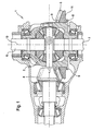
- FIG. 1 shows a section through a differential gear according to the present invention
- FIG. 2 shows a sectional illustration, in the form of a detail, of the connection point between the differential crown wheel and differential housing prior to the welding of the differential crown wheel and differential housing;
- FIG. 3 shows a sectional illustration, in the form of a detail, of the connection point between the differential crown wheel and differential housing after the welding of the differential crown wheel and differential housing.
- the differential gear 1 consists of a differential housing 2 consisting of cast iron with nodular graphite and of a differential crown wheel 3 consisting of case-hardened steel.
- the differential crown wheel 3 is connected to a drive shaft via a driving bevel pinion 4 .
- the power generated by the engine is transmitted from the drive shaft to two wheel-shaft axles 6 and 7 via the differential gear 1 .
- the wheel shafts are designed identically.
- the differential housing 2 is provided with a bearing shoulder 8 .
- the bearing shoulder 8 is integrally formed on that circumference 9 of the differential housing 2 on which the differential crown wheel 3 is pressed and extends beyond the circumference 9 of the differential housing 2 in the radial direction with respect to the axis of symmetry 10 of the differential crown wheel 3 .
- the bearing shoulder has a rectangular cross section which is dimensioned to be so narrow and short that it is soft with respect to shrinkages of a weld seam applied to the bearing shoulder 8 .
- “soft” means that the bearing shoulder 8 is capable, during the shrinkage of the weld seam 16 , of absorbing stresses possibly occurring due to movement in the axial direction with respect to the axis of symmetry 10 of the differential crown wheel 3 .
- the differential crown wheel 3 and the bearing shoulder 8 are made slender, with the result that material and construction space can be saved. Furthermore, this configuration contributes to minimizing the pinion offset.
- the differential crown wheel 3 is pressed onto the differential housing 2 in such a way that that side 11 of said differential crown wheel which faces away from the toothing faces the bearing shoulder 8 .
- a nickel-containing additional material in the form of an annular foil 12 is pushed onto the differential housing 2 , so that, as illustrated in FIG. 2, after said differential crown wheel has been pressed on, the ring 12 comes to lie between the bearing shoulder 8 and the differential crown wheel 3 .
- the ring 12 may serve as a means for positioning the differential crown wheel 3 on the housing 2 .
- the position of the differential crown wheel 3 on the differential housing 2 can be influenced and accurately determined via the thickness of the ring 12 .
- X10CrNiTi18 9 proved particularly favourable as additional material with a thickness of 0.25 mm.
- Pure nickel may, however, also be used.
- the foil may, however, also have a different thickness in the range of 0.1 to 0.3 mm.
- the inside diameter 13 of the foil 12 is greater than the circumference 9 of the differential housing 2 , so that a gap 14 is obtained between the bearing shoulder 8 and the differential crown wheel 3 below the ring 12 .
- the outside diameter 15 is exactly as large as the circumference 16 of the bearing shoulder 8 . This geometric configuration ensures that the additional material is distributed uniformly over the entire height and length of the joint and is optimally intermixed with the melt in all regions during welding.
- the gap 14 ensures that the weld seam 17 is free of detrimental actions from below.
- the use of the additional material makes it possible that the differential crown wheel 3 and the differential housing 2 can be welded to one another in spite of the high carbon contents, without the structural parts having to be prepared for the welding operation.
- the nickel in the additional material gives rise, in the solidified weld seam 17 , to buffering between the brittle structural constituents formed during cooling and thereby prevents the formation of cracks in the weld seam 17 .
- FIG. 3 shows a section through a differential gear 2 with a differential crown wheel 3 which are welded to one another via the bearing shoulder 8 .
- the weld seam 17 is arranged and is of wedge-shaped design with respect to the axis of symmetry 10 of the differential crown wheel 3 .
- the weld seam has flanks 18 which are distinguished by a low gradient. In the exemplary embodiment illustrated, the angle a amounts to approximately 6°.
- the result of this low gradient of the flanks 18 is that shrinkage during cooling takes place essentially perpendicularly to the orientation of the weld seam 17 .
- This movement brings about an axial displacement of the differential crown wheel 3 and is absorbed by the bearing shoulder 8 which, as already stated, is made soft in this respect.
- the inherent stresses in the weld seam 17 are thereby reduced considerably.
- the bearing shoulder 8 has an outer flank 19 which runs parallel to the orientation of the weld seam 17 . This allows a production-compatible ultrasonic check of the quality of the weld seam 17 .
Landscapes
- Engineering & Computer Science (AREA)
- General Engineering & Computer Science (AREA)
- Mechanical Engineering (AREA)
- Retarders (AREA)
- Gears, Cams (AREA)
Abstract
Description
Claims (9)
Applications Claiming Priority (3)
| Application Number | Priority Date | Filing Date | Title |
|---|---|---|---|
| DE10013429.7-12 | 2000-03-17 | ||
| DE10013429A DE10013429C5 (en) | 2000-03-17 | 2000-03-17 | differential |
| DE10013429 | 2000-03-17 |
Publications (2)
| Publication Number | Publication Date |
|---|---|
| US20010039228A1 US20010039228A1 (en) | 2001-11-08 |
| US6656079B2 true US6656079B2 (en) | 2003-12-02 |
Family
ID=7635384
Family Applications (1)
| Application Number | Title | Priority Date | Filing Date |
|---|---|---|---|
| US09/810,528 Expired - Fee Related US6656079B2 (en) | 2000-03-17 | 2001-03-19 | Differential gear and method of making same |
Country Status (2)
| Country | Link |
|---|---|
| US (1) | US6656079B2 (en) |
| DE (1) | DE10013429C5 (en) |
Cited By (14)
| Publication number | Priority date | Publication date | Assignee | Title |
|---|---|---|---|---|
| US20070029290A1 (en) * | 2003-10-02 | 2007-02-08 | Magna Drivetrain Ag & Co Kg | Method for the plasma, laser or electron beam welding of identical or different materials with a tendency for excessive hardening, with copper or a copper alloy as a filler material |
| US20070287570A1 (en) * | 2004-07-17 | 2007-12-13 | Zf Friedrichshafen Ag | Differential for a Vehicle Axle |
| US20090258750A1 (en) * | 2008-04-15 | 2009-10-15 | Ziech James F | Vehicle differential |
| US20100283343A1 (en) * | 2009-05-06 | 2010-11-11 | Brust Eric A | Rotor gear for a generator |
| US20100284835A1 (en) * | 2009-05-06 | 2010-11-11 | Allen Edward C | Pump gear and pump assembly for a generator |
| US20100310364A1 (en) * | 2008-02-13 | 2010-12-09 | Siegfried Botsch | Turbine housing and method for producing a turbine housing |
| US20100327684A1 (en) * | 2009-06-30 | 2010-12-30 | Grosskopf Andrew P | Idler gear for a generator |
| US20110319220A1 (en) * | 2009-01-27 | 2011-12-29 | Toyota Jidosha Kabushiki Kaisha | Differential device |
| US20130074649A1 (en) * | 2010-06-04 | 2013-03-28 | Toyota Jidosha Kabushiki Kaisha | Structure for fastening ring gear to differential case, and differential device employing same |
| US20130074648A1 (en) * | 2010-06-04 | 2013-03-28 | Toyota Jidosha Kabushiki Kaisha | Fastening structure for ring-gear and differential case, and differential device using same |
| US20150184734A1 (en) * | 2013-12-27 | 2015-07-02 | Musashi Seimitsu Industry Co., Ltd. | Method of manufacturing differential device |
| US9097334B2 (en) | 2010-07-07 | 2015-08-04 | Toyota Jidosha Kabushiki Kaisha | Method for caulking ring gear, caulking tool used for method for caulking ring gear, and ring gear |
| US9156110B2 (en) | 2011-07-06 | 2015-10-13 | American Axle & Manufacturing, Inc. | Weldment with isolation pocket for reduction of weld-induced distortion |
| US20160084730A1 (en) * | 2014-09-22 | 2016-03-24 | Fuji Jukogyo Kabushiki Kaisha | Ultrasonic testing device and ultrasonic testing method |
Families Citing this family (17)
| Publication number | Priority date | Publication date | Assignee | Title |
|---|---|---|---|---|
| JP2005054912A (en) | 2003-08-05 | 2005-03-03 | Tochigi Fuji Ind Co Ltd | Differential device |
| DE102005023230B4 (en) * | 2005-05-04 | 2010-10-07 | Bayerische Motoren Werke Aktiengesellschaft | Method for welding a ring gear with a differential housing of a transmission |
| GB0601716D0 (en) * | 2006-01-27 | 2006-03-08 | Meritor Heavy Vehicle Sys Ltd | Differential gear casing and method |
| US7654929B2 (en) * | 2007-02-02 | 2010-02-02 | Ford Global Technologies, Llc | Assembly including a planetary pinion carrier and one-way clutch |
| DE102008000444A1 (en) | 2008-02-29 | 2009-09-03 | Zf Friedrichshafen Ag | Differential gear for motor vehicle, has individual parts like differential housing, crown wheel, differential bevel gears, differential pin and axle bevel gears |
| DE102008022261A1 (en) | 2008-05-06 | 2009-11-12 | Daimler Ag | Equalizing gear, e.g. for a gearbox, has a rivet welded with its head at a component surface and a drilling in another component to take it with plastic distortion in a reinforced positive fit |
| DE102008057370A1 (en) | 2008-11-14 | 2010-05-20 | Bayerische Motoren Werke Aktiengesellschaft | Differential gear for vehicle, has housing, in which differential housing made of cast iron is pivotably supported, where crown wheel is provided for receiving of differential housing in area of its inner diameter |
| JP5359813B2 (en) * | 2009-11-24 | 2013-12-04 | トヨタ自動車株式会社 | Vehicle differential switching device |
| DE102011101165A1 (en) | 2011-05-11 | 2012-11-15 | Daimler Ag | differential |
| DE102011087581B4 (en) | 2011-12-01 | 2022-01-05 | Schaeffler Technologies AG & Co. KG | Differential for a motor vehicle with a shrunk-on final drive wheel and a method for assembling and manufacturing such a differential |
| DE102011087579A1 (en) | 2011-12-01 | 2013-06-06 | Schaeffler Technologies AG & Co. KG | Spur gear differential for use in drive train of e.g. motor vehicle, has sun wheels, and rotational torque-transferring connection formed between inner surface of axial drive wheel and radial peripheral surface of planetary carrier |
| JP6217023B2 (en) * | 2013-12-27 | 2017-10-25 | 武蔵精密工業株式会社 | Differential device and manufacturing method thereof |
| JP6501584B2 (en) * | 2015-03-30 | 2019-04-17 | 武蔵精密工業株式会社 | Transmission |
| DE102017207126A1 (en) * | 2016-07-25 | 2018-01-25 | Deere & Company | Drive arrangement with a rotating housing connected to an output interface |
| JP6876592B2 (en) * | 2017-10-30 | 2021-05-26 | 武蔵精密工業株式会社 | Differential device |
| JP7082035B2 (en) * | 2018-11-27 | 2022-06-07 | 武蔵精密工業株式会社 | Differential device |
| CN112828485B (en) * | 2020-12-31 | 2023-03-24 | 南昌航空大学 | Device for micro laser spot welding of thrust foil |
Citations (13)
| Publication number | Priority date | Publication date | Assignee | Title |
|---|---|---|---|---|
| US4125026A (en) | 1974-12-02 | 1978-11-14 | Toyota Jidosha Kogyo Kabushiki Kaisha | Differential device for vehicles |
| US4543854A (en) * | 1983-01-11 | 1985-10-01 | Ab Volvo | Differential gear mechanism |
| US4722244A (en) * | 1985-08-30 | 1988-02-02 | Toyota Jidosha Kabushiki Kaisha | Differential gear in an automobile |
| EP0277712A1 (en) | 1987-01-22 | 1988-08-10 | Eaton Corporation | Cam follower and process for making same |
| US5422071A (en) * | 1994-04-08 | 1995-06-06 | Inco Alloys International, Inc. | Heat resistant iron/steel weld material |
| US5584777A (en) * | 1994-05-18 | 1996-12-17 | Dr. Ing. H.C.F. Porsche Ag | Differential cage for absorbing shock mounted in a differential casing |
| US5637049A (en) | 1995-10-24 | 1997-06-10 | Vehicular Technologies, Inc. | Locking differential |
| US5643129A (en) * | 1995-07-31 | 1997-07-01 | Ford Motor Company | Speed reduction gearset and torque split differential mechanism |
| US5651748A (en) * | 1994-07-19 | 1997-07-29 | New Venture Gear, Inc. | Two-speed differential |
| WO1999058287A1 (en) | 1998-05-12 | 1999-11-18 | Steyr-Daimler-Puch Fahrzeugtechnik Ag & Co. Kg | Method for joining a cast part and a case-hardened steel part and component manufactured according to said method |
| US6045479A (en) * | 1998-08-10 | 2000-04-04 | Ford Global Technologies, Inc. | Differential mechanism for an automotive vehicle having a cold formed housing assembly |
| US6061907A (en) * | 1998-08-10 | 2000-05-16 | Ford Global Technologies, Inc. | Method for making a differential mechanism for an automotive vehicle |
| US6354978B1 (en) * | 1999-10-26 | 2002-03-12 | Simplicity Manufacturing, Inc. | Differential and method for variable traction control |
-
2000
- 2000-03-17 DE DE10013429A patent/DE10013429C5/en not_active Expired - Fee Related
-
2001
- 2001-03-19 US US09/810,528 patent/US6656079B2/en not_active Expired - Fee Related
Patent Citations (13)
| Publication number | Priority date | Publication date | Assignee | Title |
|---|---|---|---|---|
| US4125026A (en) | 1974-12-02 | 1978-11-14 | Toyota Jidosha Kogyo Kabushiki Kaisha | Differential device for vehicles |
| US4543854A (en) * | 1983-01-11 | 1985-10-01 | Ab Volvo | Differential gear mechanism |
| US4722244A (en) * | 1985-08-30 | 1988-02-02 | Toyota Jidosha Kabushiki Kaisha | Differential gear in an automobile |
| EP0277712A1 (en) | 1987-01-22 | 1988-08-10 | Eaton Corporation | Cam follower and process for making same |
| US5422071A (en) * | 1994-04-08 | 1995-06-06 | Inco Alloys International, Inc. | Heat resistant iron/steel weld material |
| US5584777A (en) * | 1994-05-18 | 1996-12-17 | Dr. Ing. H.C.F. Porsche Ag | Differential cage for absorbing shock mounted in a differential casing |
| US5651748A (en) * | 1994-07-19 | 1997-07-29 | New Venture Gear, Inc. | Two-speed differential |
| US5643129A (en) * | 1995-07-31 | 1997-07-01 | Ford Motor Company | Speed reduction gearset and torque split differential mechanism |
| US5637049A (en) | 1995-10-24 | 1997-06-10 | Vehicular Technologies, Inc. | Locking differential |
| WO1999058287A1 (en) | 1998-05-12 | 1999-11-18 | Steyr-Daimler-Puch Fahrzeugtechnik Ag & Co. Kg | Method for joining a cast part and a case-hardened steel part and component manufactured according to said method |
| US6045479A (en) * | 1998-08-10 | 2000-04-04 | Ford Global Technologies, Inc. | Differential mechanism for an automotive vehicle having a cold formed housing assembly |
| US6061907A (en) * | 1998-08-10 | 2000-05-16 | Ford Global Technologies, Inc. | Method for making a differential mechanism for an automotive vehicle |
| US6354978B1 (en) * | 1999-10-26 | 2002-03-12 | Simplicity Manufacturing, Inc. | Differential and method for variable traction control |
Non-Patent Citations (3)
| Title |
|---|
| "Investigation of Laser Welding of Workpiece Combinations of Cast Iron and Steel", 1994, pp. 1-4, 39, 41-43, and 111-115. |
| "Laser and Electronic Welding of Workpiece Combinations Made of Cast Iron and other Steel Products", 1998, pp. 718-723. |
| U.S. Ser. No.: 09/810,509, copy of Specification and Filing Receipt. |
Cited By (22)
| Publication number | Priority date | Publication date | Assignee | Title |
|---|---|---|---|---|
| US20070029290A1 (en) * | 2003-10-02 | 2007-02-08 | Magna Drivetrain Ag & Co Kg | Method for the plasma, laser or electron beam welding of identical or different materials with a tendency for excessive hardening, with copper or a copper alloy as a filler material |
| US20070287570A1 (en) * | 2004-07-17 | 2007-12-13 | Zf Friedrichshafen Ag | Differential for a Vehicle Axle |
| US7465247B2 (en) | 2004-07-17 | 2008-12-16 | Zf Friedrichshafen Ag | Differential for a vehicle axle |
| US20100310364A1 (en) * | 2008-02-13 | 2010-12-09 | Siegfried Botsch | Turbine housing and method for producing a turbine housing |
| US20090258750A1 (en) * | 2008-04-15 | 2009-10-15 | Ziech James F | Vehicle differential |
| US20110319220A1 (en) * | 2009-01-27 | 2011-12-29 | Toyota Jidosha Kabushiki Kaisha | Differential device |
| US8747275B2 (en) * | 2009-01-27 | 2014-06-10 | Toyota Jidosha Kabushiki Kaisha | Differential device |
| US20100284835A1 (en) * | 2009-05-06 | 2010-11-11 | Allen Edward C | Pump gear and pump assembly for a generator |
| US20100283343A1 (en) * | 2009-05-06 | 2010-11-11 | Brust Eric A | Rotor gear for a generator |
| US8051738B2 (en) | 2009-05-06 | 2011-11-08 | Hamilton Sundstrand Corporation | Rotor gear for a generator |
| US8132480B2 (en) * | 2009-05-06 | 2012-03-13 | Hamilton Sundstrand Corporation | Pump gear and pump assembly for a generator |
| US20100327684A1 (en) * | 2009-06-30 | 2010-12-30 | Grosskopf Andrew P | Idler gear for a generator |
| US7926381B2 (en) | 2009-06-30 | 2011-04-19 | Hamilton Sundstrand Corporation | Idler gear for a generator |
| US20130074649A1 (en) * | 2010-06-04 | 2013-03-28 | Toyota Jidosha Kabushiki Kaisha | Structure for fastening ring gear to differential case, and differential device employing same |
| US20130074648A1 (en) * | 2010-06-04 | 2013-03-28 | Toyota Jidosha Kabushiki Kaisha | Fastening structure for ring-gear and differential case, and differential device using same |
| US9068640B2 (en) * | 2010-06-04 | 2015-06-30 | Toyota Jidosha Kabushiki Kaisha | Fastening structure for ring-gear and differential case, and differential device using same |
| US9097334B2 (en) | 2010-07-07 | 2015-08-04 | Toyota Jidosha Kabushiki Kaisha | Method for caulking ring gear, caulking tool used for method for caulking ring gear, and ring gear |
| US9156110B2 (en) | 2011-07-06 | 2015-10-13 | American Axle & Manufacturing, Inc. | Weldment with isolation pocket for reduction of weld-induced distortion |
| US20150184734A1 (en) * | 2013-12-27 | 2015-07-02 | Musashi Seimitsu Industry Co., Ltd. | Method of manufacturing differential device |
| US9458919B2 (en) * | 2013-12-27 | 2016-10-04 | Musashi Seimitsu Industry Co., Ltd. | Method of manufacturing differential device |
| US20160084730A1 (en) * | 2014-09-22 | 2016-03-24 | Fuji Jukogyo Kabushiki Kaisha | Ultrasonic testing device and ultrasonic testing method |
| US9594001B2 (en) * | 2014-09-22 | 2017-03-14 | Fuji Jukogyo Kabushiki Kaisha | Ultrasonic testing device and ultrasonic testing method |
Also Published As
| Publication number | Publication date |
|---|---|
| DE10013429C5 (en) | 2009-10-01 |
| DE10013429C1 (en) | 2001-07-05 |
| US20010039228A1 (en) | 2001-11-08 |
Similar Documents
| Publication | Publication Date | Title |
|---|---|---|
| US6656079B2 (en) | Differential gear and method of making same | |
| US8469598B2 (en) | Bearing unit | |
| US5314106A (en) | Method for joining steel to aluminum alloy components or titanium alloy components, and turbochargers obtained by the method | |
| US6378761B2 (en) | Process for joining components made from case-hardened steel to components made from cast iron | |
| US7294084B2 (en) | Transverse differential of a motor vehicle and method for production thereof | |
| US11668382B2 (en) | Differential overmolded weldable ring | |
| JP5614054B2 (en) | Beam welding member and differential device provided with the same | |
| US10005161B2 (en) | Large transmission gearwheel and process for producing a large transmission gearwheel | |
| JP4306903B2 (en) | Wheel bearing device | |
| EP2882983B1 (en) | Differential case assembly with drive ring gear | |
| US5857916A (en) | Motor vehicle drive shaft comprising a straight seam welded pipe of an aluminum alloy | |
| EP0969946B1 (en) | Friction welded shaft | |
| US10882354B2 (en) | Wheel hub for heavy-duty vehicles | |
| EP3470705B1 (en) | Vehicular differential device and welding method for the same | |
| US20030057052A1 (en) | Clutch shaft stress relief | |
| CA2440084A1 (en) | Shaft comprising a part connected thereto by welding | |
| CN111168239B (en) | Fusion welding of ferroalloy components using low carbon steel strip | |
| RU2469876C2 (en) | Vehicle axle | |
| KR100241851B1 (en) | Automotive power transmission shaft | |
| JP2000230537A (en) | Strong driving shaft having superior torsional fatigue characteristic, and manufacture thereof | |
| US20080314877A1 (en) | Plasma Keyhole Welding of Hardenable Steel | |
| JP2001074060A (en) | Sliding yoke and manufacture thereof | |
| JP2002213429A (en) | Propeller shaft | |
| JPH06341422A (en) | High performance automobile drive shaft excellent in torsional fatigue characteristic | |
| JPH10184804A (en) | Driving shaft having excellent torsional fatigue characteristics |
Legal Events
| Date | Code | Title | Description |
|---|---|---|---|
| AS | Assignment |
Owner name: DAIMLERCHRYSLER AG, GERMANY Free format text: ASSIGNMENT OF ASSIGNORS INTEREST;ASSIGNORS:EULENSTEIN, TYCHO;NETUSCHIL, WILLI;PAASCH, RUDOLF;REEL/FRAME:011930/0854;SIGNING DATES FROM 20010322 TO 20010416 |
|
| FPAY | Fee payment |
Year of fee payment: 4 |
|
| AS | Assignment |
Owner name: DAIMLER AG, GERMANY Free format text: CHANGE OF NAME;ASSIGNOR:DAIMLERCHRYSLER AG;REEL/FRAME:020976/0889 Effective date: 20071019 Owner name: DAIMLER AG,GERMANY Free format text: CHANGE OF NAME;ASSIGNOR:DAIMLERCHRYSLER AG;REEL/FRAME:020976/0889 Effective date: 20071019 |
|
| REMI | Maintenance fee reminder mailed | ||
| LAPS | Lapse for failure to pay maintenance fees | ||
| STCH | Information on status: patent discontinuation |
Free format text: PATENT EXPIRED DUE TO NONPAYMENT OF MAINTENANCE FEES UNDER 37 CFR 1.362 |
|
| FP | Lapsed due to failure to pay maintenance fee |
Effective date: 20111202 |
|
| AS | Assignment |
Owner name: DAIMLER AG, GERMANY Free format text: CORRECTIVE ASSIGNMENT TO CORRECT THE APPLICATION NO. 10/567,810 PREVIOUSLY RECORDED ON REEL 020976 FRAME 0889. ASSIGNOR(S) HEREBY CONFIRMS THE CHANGE OF NAME;ASSIGNOR:DAIMLERCHRYSLER AG;REEL/FRAME:053583/0493 Effective date: 20071019 |