US6640171B2 - Motor vehicle with supplemental rear steering having open and closed loop modes - Google Patents
Motor vehicle with supplemental rear steering having open and closed loop modes Download PDFInfo
- Publication number
- US6640171B2 US6640171B2 US09/921,634 US92163401A US6640171B2 US 6640171 B2 US6640171 B2 US 6640171B2 US 92163401 A US92163401 A US 92163401A US 6640171 B2 US6640171 B2 US 6640171B2
- Authority
- US
- United States
- Prior art keywords
- yaw rate
- steer angle
- rate error
- closed loop
- deriving
- Prior art date
- Legal status (The legal status is an assumption and is not a legal conclusion. Google has not performed a legal analysis and makes no representation as to the accuracy of the status listed.)
- Expired - Fee Related
Links
Images


Classifications
-
- B—PERFORMING OPERATIONS; TRANSPORTING
- B60—VEHICLES IN GENERAL
- B60K—ARRANGEMENT OR MOUNTING OF PROPULSION UNITS OR OF TRANSMISSIONS IN VEHICLES; ARRANGEMENT OR MOUNTING OF PLURAL DIVERSE PRIME-MOVERS IN VEHICLES; AUXILIARY DRIVES FOR VEHICLES; INSTRUMENTATION OR DASHBOARDS FOR VEHICLES; ARRANGEMENTS IN CONNECTION WITH COOLING, AIR INTAKE, GAS EXHAUST OR FUEL SUPPLY OF PROPULSION UNITS IN VEHICLES
- B60K28/00—Safety devices for propulsion-unit control, specially adapted for, or arranged in, vehicles, e.g. preventing fuel supply or ignition in the event of potentially dangerous conditions
- B60K28/10—Safety devices for propulsion-unit control, specially adapted for, or arranged in, vehicles, e.g. preventing fuel supply or ignition in the event of potentially dangerous conditions responsive to conditions relating to the vehicle
- B60K28/16—Safety devices for propulsion-unit control, specially adapted for, or arranged in, vehicles, e.g. preventing fuel supply or ignition in the event of potentially dangerous conditions responsive to conditions relating to the vehicle responsive to, or preventing, skidding of wheels
-
- B—PERFORMING OPERATIONS; TRANSPORTING
- B60—VEHICLES IN GENERAL
- B60T—VEHICLE BRAKE CONTROL SYSTEMS OR PARTS THEREOF; BRAKE CONTROL SYSTEMS OR PARTS THEREOF, IN GENERAL; ARRANGEMENT OF BRAKING ELEMENTS ON VEHICLES IN GENERAL; PORTABLE DEVICES FOR PREVENTING UNWANTED MOVEMENT OF VEHICLES; VEHICLE MODIFICATIONS TO FACILITATE COOLING OF BRAKES
- B60T8/00—Arrangements for adjusting wheel-braking force to meet varying vehicular or ground-surface conditions, e.g. limiting or varying distribution of braking force
- B60T8/17—Using electrical or electronic regulation means to control braking
- B60T8/176—Brake regulation specially adapted to prevent excessive wheel slip during vehicle deceleration, e.g. ABS
- B60T8/1764—Regulation during travel on surface with different coefficients of friction, e.g. between left and right sides, mu-split or between front and rear
-
- B—PERFORMING OPERATIONS; TRANSPORTING
- B60—VEHICLES IN GENERAL
- B60W—CONJOINT CONTROL OF VEHICLE SUB-UNITS OF DIFFERENT TYPE OR DIFFERENT FUNCTION; CONTROL SYSTEMS SPECIALLY ADAPTED FOR HYBRID VEHICLES; ROAD VEHICLE DRIVE CONTROL SYSTEMS FOR PURPOSES NOT RELATED TO THE CONTROL OF A PARTICULAR SUB-UNIT
- B60W30/00—Purposes of road vehicle drive control systems not related to the control of a particular sub-unit, e.g. of systems using conjoint control of vehicle sub-units, or advanced driver assistance systems for ensuring comfort, stability and safety or drive control systems for propelling or retarding the vehicle
- B60W30/18—Propelling the vehicle
- B60W30/18009—Propelling the vehicle related to particular drive situations
- B60W30/18145—Cornering
-
- B—PERFORMING OPERATIONS; TRANSPORTING
- B62—LAND VEHICLES FOR TRAVELLING OTHERWISE THAN ON RAILS
- B62D—MOTOR VEHICLES; TRAILERS
- B62D7/00—Steering linkage; Stub axles or their mountings
- B62D7/06—Steering linkage; Stub axles or their mountings for individually-pivoted wheels, e.g. on king-pins
- B62D7/14—Steering linkage; Stub axles or their mountings for individually-pivoted wheels, e.g. on king-pins the pivotal axes being situated in more than one plane transverse to the longitudinal centre line of the vehicle, e.g. all-wheel steering
- B62D7/15—Steering linkage; Stub axles or their mountings for individually-pivoted wheels, e.g. on king-pins the pivotal axes being situated in more than one plane transverse to the longitudinal centre line of the vehicle, e.g. all-wheel steering characterised by means varying the ratio between the steering angles of the steered wheels
- B62D7/159—Steering linkage; Stub axles or their mountings for individually-pivoted wheels, e.g. on king-pins the pivotal axes being situated in more than one plane transverse to the longitudinal centre line of the vehicle, e.g. all-wheel steering characterised by means varying the ratio between the steering angles of the steered wheels characterised by computing methods or stabilisation processes or systems, e.g. responding to yaw rate, lateral wind, load, road condition
-
- B—PERFORMING OPERATIONS; TRANSPORTING
- B60—VEHICLES IN GENERAL
- B60T—VEHICLE BRAKE CONTROL SYSTEMS OR PARTS THEREOF; BRAKE CONTROL SYSTEMS OR PARTS THEREOF, IN GENERAL; ARRANGEMENT OF BRAKING ELEMENTS ON VEHICLES IN GENERAL; PORTABLE DEVICES FOR PREVENTING UNWANTED MOVEMENT OF VEHICLES; VEHICLE MODIFICATIONS TO FACILITATE COOLING OF BRAKES
- B60T2260/00—Interaction of vehicle brake system with other systems
- B60T2260/02—Active Steering, Steer-by-Wire
- B60T2260/022—Rear-wheel steering; Four-wheel steering
-
- B—PERFORMING OPERATIONS; TRANSPORTING
- B60—VEHICLES IN GENERAL
- B60T—VEHICLE BRAKE CONTROL SYSTEMS OR PARTS THEREOF; BRAKE CONTROL SYSTEMS OR PARTS THEREOF, IN GENERAL; ARRANGEMENT OF BRAKING ELEMENTS ON VEHICLES IN GENERAL; PORTABLE DEVICES FOR PREVENTING UNWANTED MOVEMENT OF VEHICLES; VEHICLE MODIFICATIONS TO FACILITATE COOLING OF BRAKES
- B60T2260/00—Interaction of vehicle brake system with other systems
- B60T2260/02—Active Steering, Steer-by-Wire
- B60T2260/024—Yawing moment compensation during mu-split braking
-
- B—PERFORMING OPERATIONS; TRANSPORTING
- B60—VEHICLES IN GENERAL
- B60W—CONJOINT CONTROL OF VEHICLE SUB-UNITS OF DIFFERENT TYPE OR DIFFERENT FUNCTION; CONTROL SYSTEMS SPECIALLY ADAPTED FOR HYBRID VEHICLES; ROAD VEHICLE DRIVE CONTROL SYSTEMS FOR PURPOSES NOT RELATED TO THE CONTROL OF A PARTICULAR SUB-UNIT
- B60W50/00—Details of control systems for road vehicle drive control not related to the control of a particular sub-unit, e.g. process diagnostic or vehicle driver interfaces
- B60W2050/0001—Details of the control system
- B60W2050/0002—Automatic control, details of type of controller or control system architecture
- B60W2050/0012—Feedforward or open loop systems
-
- B—PERFORMING OPERATIONS; TRANSPORTING
- B60—VEHICLES IN GENERAL
- B60W—CONJOINT CONTROL OF VEHICLE SUB-UNITS OF DIFFERENT TYPE OR DIFFERENT FUNCTION; CONTROL SYSTEMS SPECIALLY ADAPTED FOR HYBRID VEHICLES; ROAD VEHICLE DRIVE CONTROL SYSTEMS FOR PURPOSES NOT RELATED TO THE CONTROL OF A PARTICULAR SUB-UNIT
- B60W2520/00—Input parameters relating to overall vehicle dynamics
- B60W2520/14—Yaw
-
- B—PERFORMING OPERATIONS; TRANSPORTING
- B60—VEHICLES IN GENERAL
- B60W—CONJOINT CONTROL OF VEHICLE SUB-UNITS OF DIFFERENT TYPE OR DIFFERENT FUNCTION; CONTROL SYSTEMS SPECIALLY ADAPTED FOR HYBRID VEHICLES; ROAD VEHICLE DRIVE CONTROL SYSTEMS FOR PURPOSES NOT RELATED TO THE CONTROL OF A PARTICULAR SUB-UNIT
- B60W2520/00—Input parameters relating to overall vehicle dynamics
- B60W2520/28—Wheel speed
-
- B—PERFORMING OPERATIONS; TRANSPORTING
- B60—VEHICLES IN GENERAL
- B60W—CONJOINT CONTROL OF VEHICLE SUB-UNITS OF DIFFERENT TYPE OR DIFFERENT FUNCTION; CONTROL SYSTEMS SPECIALLY ADAPTED FOR HYBRID VEHICLES; ROAD VEHICLE DRIVE CONTROL SYSTEMS FOR PURPOSES NOT RELATED TO THE CONTROL OF A PARTICULAR SUB-UNIT
- B60W2540/00—Input parameters relating to occupants
- B60W2540/18—Steering angle
Definitions
- the technical field of this invention is rear steering for a motor vehicle.
- the invention described and claimed herein relates to a rear steer control for a motor vehicle that considers vehicle velocity in three ranges and provides an out of phase rear steer angle in open loop control within a low velocity range for oversteer assistance of parking and similar vehicle maneuvers, an in phase rear steer angle in closed loop control responsive to vehicle yaw rate within a high velocity range for understeer vehicle stability assistance and a steer angle in closed loop control responsive to vehicle yaw rate within an intermediate velocity range.
- the closed loop control in the high velocity range may be combined with an open loop control.
- the control optionally provides supplemental throttle adjustments in coordination with the rear steer control for increased traction and stability in a turn.
- FIG. 1 shows a schematic diagram of a motor vehicle with a rear steer control according to the invention.
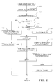
- FIG. 2 shows a flow chart of a rear steer control for use in the vehicle of FIG. 1 .
- FIG. 3 shows a flow chart of a subroutine used in the control program of FIG. 2 .
- FIGS. 4 and 5 are schematic diagrams demonstrating in phase and out of phase rear steering.
- FIGS. 6A, 6 B, and 7 - 11 are flow charts of additional subroutines used in the control program of FIG. 2 .
- a motor vehicle 10 has a front axle 11 with left front wheel 12 and right front wheel 13 and a rear axle 14 with left rear wheel 15 and right rear wheel 16 .
- Front wheels 12 , 13 are steered by a known front steering apparatus 20 responsive to an operator control 21 such as a standard steering wheel (hand wheel).
- Front steering apparatus 20 may be mechanical, electro-hydraulic or electric of any known and appropriate construction and operation and provide a front steering angle to front wheels 12 , 13 .
- front steering apparatus 20 may preferably be a standard rack and pinion steering apparatus with power assist; and front wheels 12 , 13 may be steered to a common steering angle.
- Rear wheels 15 , 16 are steerable by a rear steer apparatus 22 controlled by a rear steer control 23 of this invention to supplement the steering action of front wheels 15 and 16 as described herein.
- a vehicle propulsion apparatus 24 provides motive power to at least one of the pairs of front wheels 12 , 13 (front wheel drive) or rear wheels 15 , 16 (rear wheel drive).
- Rear steer control 23 preferably includes a microcomputer based controller receiving inputs from several sensors on vehicle 10 .
- Front steer apparatus 20 includes a steering wheel angle sensor that measures the operator steering input and outputs a steering wheel angle signal ⁇ SWA .
- Wheel speed sensors 25 on each of the non-driven wheels provide wheel speed signals V W that can be averaged to provide a longitudinal vehicle velocity signal V X . Alternatively, this signal may be provided by any other known vehicle speed sensor, especially if all wheels are driven.
- a yaw rate sensor 26 provides a vehicle yaw rate signal ⁇
- a lateral acceleration sensor 27 provides a vehicle lateral acceleration signal a y .
- a throttle input signal is provided by propulsion apparatus 24 .
- Subroutine REAR STEER COMMAND the rear steer control for vehicle 10 , is provided to vehicle 10 in the form of a stored computer program to be run by the microcomputer therein and is shown in flow chart form in FIG. 2 . It begins at step 100 by obtaining sensor values from the steering wheel angle sensor in front steer apparatus 20 , the wheel speed sensors 25 on the non-driven wheels, the lateral acceleration sensor 27 and the yaw rate sensor 26 . It continues at step 102 by deriving a vehicle speed signal V X , for example by averaging the sensed wheel speeds of the non-driven wheels. Thus, signals for measured yaw rate ⁇ , measured lateral acceleration a y , throttle input and individual wheel speeds V W are available for use in the remainder of the subroutine.
- the subroutine compares the derived vehicle speed signal V X with a low speed reference LOREF, for example 10 miles per hour (mph). If V X is less than reference LOREF, the subroutine calls another subroutine OPEN LOOP at step 106 .
- Subroutine OPEN LOOP which will be described in greater detail below, derives an open loop rear steer angle command from a front steer angle and the value of vehicle speed V X .
- the rear steer angle command is applied, at step 108 , out of phase with the front steer angle.
- the phrase “out of phase” applied to the rear steer angle means that the rear steer angle is measured from the straight ahead direction in opposite rotation to that of the front steer angle. This is shown schematically in FIG.
- front wheels 12 , 13 are turned to the right and rear wheels 15 , 16 are turned to the left, although the angle is exaggerated for ease of understanding.
- the out of phase rear steer provides a supplemental oversteer to assist in parking and other low speed maneuvers.
- the subroutine compares it to a high reference HIREF, for example 30 mph, at step 110 . If the value of V X exceeds HIREF, the subroutine sets a flag COMB at step 112 to indicate combined open loop and closed loop and calls subroutine OPEN LOOP at step 114 to provide an open loop rear steer angle command. The subroutine then calls a subroutine CLOSED LOOP at step 116 . Subroutine CLOSED LOOP, which will be described in greater detail below, derives a closed loop rear steer angle command in response to computed yaw rate and side slip rate errors.
- HIREF high reference
- HIREF for example 30 mph
- Subroutine REAR STEER COMMAND next adds the open and closed loop rear steer angle commands provided by subroutines OPEN LOOP and CLOSED LOOP at step 118 and applies the resulting combined rear steer angle command in phase at step 120 .
- the phrase “in phase” applied to the rear steer angle command means the opposite of “out of phase”: that is, measured in the same rotation as that of the front steer angle, as shown schematically in FIG. 4, in which both the front wheels and the rear wheels are turned to the right.
- the in phase rear steer provides a supplemental understeer at high vehicle speeds to promote directional stability.
- the combination of open loop and closed loop control provides the ability to operate with the open loop value alone if the closed loop value becomes unavailable.
- step 110 if the value of V X is not greater than HIREF, the COMB flag is reset at 122 ; and subroutine CLOSED LOOP is called at step 124 .
- the output closed loop rear steer angle command is then applied at step 126 , in or out of phase as determined by the subroutine.
- HIREF and LOREF e.g. 10-30 mph
- an out of phase supplemental rear steer is provided but is limited in closed loop responsive to yaw rate and side slip errors to enhance stability in the upper part of the range.
- Subroutine OPEN LOOP is described with reference to the flow chart of FIG. 3 . It begins at step 140 by deriving a FRONT STEER ANGLE which is the angle between the front wheels and the longitudinal vehicle axis. In the case of a standard rack and pinion or other mechanical steering apparatus, this is easily accomplished by multiplying the steering wheel (hand wheel) angle ⁇ SWA by a gain representing the gear ratio of the front steering apparatus:
- a vehicle velocity dependent gain G(V X ) is obtained, preferably from a lookup table with longitudinal vehicle velocity V X as an input.
- the REAR STEER ANGLE COMMAND is generated by multiplying the FRONT STEER ANGLE derived in step 140 :
- the sign of gain G(VX) may be conveniently chosen to ensure an out of phase rear steer angle command.
- Subroutine CLOSED LOOP is described with reference to the flow chart of FIGS. 6A, 6 B. It begins at step 150 by checking the COMB flag to determine whether the mode of operation is combined closed and open loop (in the high range of vehicle velocity) or closed loop only (in the intermediate range of vehicle velocity). If the flag is set the combined mode is indicated; and the subroutine determines a desired closed loop yaw rate at step 152 in a table lookup using a table stored for use in the combined mode. The table stores values of desired yaw rate as a function of longitudinal vehicle velocity V X and FRONT STEER ANGLE.
- step 150 If the COMB flag is found to be reset at step 150 , the closed loop only mode is indicated; and the subroutine proceeds to step 154 and performs a table lookup of desired yaw rate in a similar table storing values appropriate for the closed loop only mode.
- the subroutine next calculates a proportional yaw rate error signal PYAWERR at step 156 as the difference between the determined desired yaw rate ⁇ d and the measured yaw rate ⁇ :
- the subroutine calculates a derivative yaw rate error signal DYAWERR by differentiating PYAWERR:
- DYAWERR n PYAWERR n ⁇ PYAWERR n ⁇ 1 .
- the subroutine calculates a side slip rate error term, which is simplified by an assumption that the desired side slip rate equals zero.
- the side slip rate error term is then just the negative of the actual side slip rate:
- the subroutine calculates an integral yaw rate error term, which can be accomplishes in digital terms as an accumulated sum:
- IYAWERR n IYAWERR n ⁇ 1 +PYAWERR n ,
- IYAWERR n is the present value of the integral of the yaw rate error
- IYAWERR n ⁇ 1 is the previous value thereof
- PYAWERR n is the present value of the yaw rate error
- the subroutine calls another subroutine SURFACE COEFFICIENT to derive an estimated surface coefficient of friction of the road surface.
- the latter subroutine will be described in more detail below.
- the subroutine determines whether the vehicle is in an understeer or an oversteer mode. The determination of oversteer or understeer is well known in the art and is used in many vehicle yaw stability controls in use in production vehicles and shown in patents such as one or more of U.S. Pat. Nos. 6,122,584, 5,720,533, 5,746,486 and 5,941,919.
- step 166 determines whether the result of step 166 is a determination of understeer.
- DVLR also symbolized as ⁇ V LR , is a commanded difference between the right and left wheel velocities.
- DVLR U is equal to a weighted sum of the proportional yaw rate error term, the derivative yaw rate error term and the integral yaw rate error term:
- the integral yaw rate error term is reset to zero before calculating DVLRU if any of the following conditions is met:
- step 166 if the vehicle is in oversteer, the subroutine proceeds to step 170 , in which it calculates a commanded DVLR for the rear wheels as a weighted sum of the proportional yaw rate error term, the derivative yaw rate error term and a slip rate error term:
- the gains G SO , G PO and G DO are stored in memory as functions of surface coefficient ⁇ e , generally decreasing with increasing ⁇ e .
- step 172 a REAR STEER ANGLE COMMAND is derived by multiplying DVLR by a calibrated constant conversion factor having a negative sign and a magnitude dependent on the vehicle chassis geometry and tire properties (example, ⁇ 0.5).
- step 172 would be followed by slew rate limiting and filtering the REAR STEER COMMAND and then returning from the subroutine. But in this embodiment, an supplemental modification is included.
- the subroutine proceeds to compare the magnitude of the steering wheel angle (indicative of driver steer input) with a first threshold THRESH 1 at step 174 . If it is not greater than the threshold, the subroutine proceeds to compare the driver throttle input with a second threshold THRESH 2 . If it is not greater than the threshold, the subroutine proceeds to slew limit (step 180 ) and filter (step 182 ) the REAR STEER COMMAND and return. But if the answer is yes (greater than) in either of steps 174 and 176 , the subroutine proceeds to modify the REAR STEER COMMAND and perhaps send a throttle modification to propulsion apparatus 24 before proceeding to step 180 .
- step 178 in the previous paragraph is described as an additional subroutine in the flow chart of FIG. 8, which shows a particular modification for a vehicle with rear wheel propulsion and supplemental rear wheel steer.
- Subroutine STEER AND THROTTLE SUPPLEMENT begins by determining an understeer mode at step 184 . If understeer is indicated, the subroutine decreases REAR STEER ANGLE COMMAND for the rear wheels by a predetermined value at step 186 . The subroutine then determines at step 188 if the absolute value of the outer rear wheel slip is less than a threshold THRESH 3 . If it is, a command is sent at step 190 to propulsion apparatus 24 to increase the throttle command by a predetermined value.
- step 190 is skipped.
- step 190 is skipped.
- REAR STEER ANGLE COMMAND is increased at step 192 for the rear wheels by a predetermined value.
- step 194 the absolute value of the outer rear slip is compared with a threshold THRESH 4 and, if it is not less, a command to decrease the throttle command by a predetermined value is sent at step 196 to propulsion control 24 .
- FIG. 9 describes the modification of step 178 for a vehicle with front wheel propulsion and supplemental rear wheel steer.
- Subroutine STEER AND THROTTLE SUPPLEMENT begins by determining an understeer mode at step 200 . If understeer is indicated, the subroutine decreases REAR STEER ANGLE COMMAND for the rear wheels by a predetermined value at step 202 . The subroutine then determines at step 204 if the outer front wheel slip is less than a threshold THRESH 3 . If it is not less, a command is sent at step 206 to propulsion apparatus 24 to decrease the throttle command by a predetermined value. If the outer front wheel slip is less than THRESH 3 , step 206 is skipped.
- step 200 if oversteer is indicated, REAR STEER ANGLE COMMAND is increased at step 208 for the rear wheels by a predetermined value.
- step 210 the outer front slip is compared with a threshold THRESH 4 and, if it is less, a command to increase the throttle command by a predetermined value is sent at step 212 to propulsion control 24 .
- FIGS. 10 and 11 describe variations of the modification of step 178 for a vehicle with an electronically controlled front steering apparatus 20 and may be used in a vehicle that does not have rear wheel steering.
- the front steering apparatus may be any type of steering apparatus providing independent steer angle control of each of the front wheels in an automatic manner relative to operator input, such as in response to an electronic command signal.
- subroutine STEER AND THROTTLE SUPPLEMENT begins by determining an understeer mode at step 220 . If understeer is indicated, the subroutine determines at step 222 if the magnitude of the outer front wheel slip is less than a threshold THRESH 3 . If this is true, then the subroutine increases a FRONT STEER ANGLE COMMAND for the outer front wheel at step 224 . If it is not true, then a command is sent at step 226 to propulsion apparatus 24 to decrease the throttle command by a predetermined value.
- the subroutine determines at step 230 if the outer front wheel slip is less than a threshold THRESH 4 . If it is true, a command to increase the throttle command by a predetermined value is sent at step 232 to propulsion control 24 . If it is not true, the subroutine decreases a FRONT STEER ANGLE COMMAND to both front wheels at step 234 .
- subroutine STEER AND THROTTLE SUPPLEMENT begins by determining an understeer mode at step 240 . If understeer is indicated, the subroutine increases a FRONT STEER ANGLE COMMAND for both front wheels at step 242 and then determines at step 244 if the magnitude of the outer rear wheel slip is less than a threshold THRESH 3 . If this is true at step 244 , then a command is sent at step 246 to propulsion apparatus 24 to increase the throttle command by a predetermined value. If it is not true, then step 246 is skipped.
- step 240 if oversteer is indicated, the subroutine decreases a FRONT STEER ANGLE COMMAND to both front wheels at step 250 and then determines at step 252 if the outer rear wheel slip is less than a threshold THRESH 4 . If it is not true at step 252 , a command to decrease the throttle command by a predetermined value is sent at step 254 to propulsion control 24 . If it is true, step 254 is skipped.
- Subroutine SURFACE COEFFICIENT is described with reference to FIG. 7, which show a flow chart of subroutine SURFACE COEFFICIENT.
- This subroutine calculates an estimated surface coefficient of adhesion ⁇ e .
- the subroutine is designed to recognize situations when vehicle 10 operates at or close to the limit of adhesion and estimate a lateral surface coefficient of adhesion ⁇ L from measured lateral acceleration a y . This estimate is calculated by identifying the one of the following three conditions.
- entry conditions are when vehicle 10 is handling at the limit of adhesion and is not in a quick transient maneuver.
- the coefficient of adhesion is calculated as a ratio of the magnitude of lateral acceleration a y to the maximum lateral acceleration a ymax that vehicle 10 can develop on dry surface.
- the surface estimate is held unchanged from a previous value (i.e. holding conditions).
- the only exception is when the magnitude of measured lateral acceleration a y exceeds the maximum value predicted using currently held estimate. In this case the estimate is calculated as if vehicle 10 was in an entry condition.
- the subroutine begins at step 60 by obtaining certain information. It is recognized that the most robust signal available is yaw rate ⁇ , and the entry and exit conditions are dependent mainly on a yaw rate error, i.e. a difference between the desired yaw rate ⁇ d and measured yaw rate ⁇ , and to a lesser extent on measured lateral acceleration a y (entry condition only). Thus, the yaw rate error ⁇ d ⁇ and lateral acceleration a y are obtained as described above and filtered.
- a temporary surface coefficient ⁇ L — temp is derived.
- a surface coefficient of adhesion can be determined as a ratio of the magnitude of a filtered lateral acceleration a yfilt to a maximum lateral acceleration a ymax that vehicle 10 can sustain on dry pavement as shown in the following equation:
- ⁇ L — ay is an intermediate, temporary estimate of surface coefficient of adhesion in the lateral direction
- a yfilt is filtered lateral acceleration, which is also corrected for the effects of measured gravity components resulting from vehicle body roll and bank angle of the road.
- ⁇ L ⁇ L — ay *( c l +c 2 * ⁇ L — ay )
- a condition is used that requires both the desired yaw rate ⁇ d and lateral acceleration a y to have the same signs for a specific time period (necessary for the acceleration to build up).
- a timer is introduced, for example based on a timer interrupt from a real time clock.
- timer becomes zero when the desired yaw rate ⁇ d and lateral acceleration a y have opposite signs and counts the time that elapses from the moment the signs become and remain the same.
- timer ⁇ 0 when ⁇ ⁇ ⁇ ⁇ d * a yfiltl ⁇ Ay_sign ⁇ _comp timer + loop_time otherwise
- ⁇ d is the desired yaw rate in [rad/s] and Ay_sign_comp is a constant with a typical value of 0.2 m/s 3 .
- a ymin is a constant with a typical value of 0.2 m/s 2 .
- a yfilt is very small in magnitude, it is replaced by the a ymin with a sign the same as the desired yaw rate ⁇ d .
- This limit is needed to improve estimation on very slick surfaces (e.g. ice) when the magnitude of lateral acceleration a y is comparable to the effect of noise, so that the sign of a yfilt cannot be established.
- Subroutine SURFACE COEFFICIENT finds the entry conditions to be met at step 62 when the following three (3) conditions are simultaneously satisfied.
- the first condition deals with the size of the magnitude of yaw rate error. Either (1) the magnitude of the yaw rate error is greater than a threshold:
- Yaw_Threshold2 depends on the magnitude of desired yaw rate ⁇ d or measured yaw rate ⁇ .
- Yaw_Threshold2 4 deg/s+5*
- 0.07 rad/s+0.09*
- ⁇ d is the desired yaw rate in [rad/s].
- a typical value of the time period Te for which this condition must be satisfied is 0.3 sec.
- the threshold Yaw_Threshold 1 used may also depend on the magnitude of desired yaw rate ⁇ d or measured yaw rate ⁇ .
- the second condition is that the signs of the measured lateral acceleration a y and filtered lateral acceleration a yfil and a weighted sum of yaw rate ⁇ and the derivative of yaw rate are the same in accordance with the following mathematical expression:
- ⁇ is the measured yaw rate and d ⁇ /dt is its derivative.
- the recommended values for the constant Yaw_Der_Mult is 0.5 and for Sign_Comp is 0.035 (if ⁇ is in rad/s and d ⁇ /dt in rad/s 2 ).
- the third condition is that either (1) the signs of the desired yaw rate ⁇ d and measured lateral acceleration a y are the same and they have been the same for some time in accordance with following equation:
- hold_time can be 0.25 s, or (2) the magnitude of a derivative of lateral acceleration da y /dt is less than a threshold in accordance with the following mathematical equation (45):
- a recommended value of the threshold, Ay_Der_Thresh 2.5 m/s 3 .
- step 64 determines the surface coefficient to be the temporary surface estimate ⁇ L as described above and then proceeds to step 66 .
- the subroutine skips step 64 and proceeds directly to step 66 .
- the subroutine tests the exit conditions.
- the exit conditions are met when the following two (2) conditions are simultaneously satisfied.
- the first condition is the magnitude of yaw rate error as filtered is less than or equal to a threshold as illustrated in the following equation:
- the second condition is that a low-pass filtered version of the magnitude of the yaw rate error is less than or equal to a threshold as illustrated in the following equation:
- the thresholds Yaw_Threshold 3 and Yaw_Thereshold 4 may depend on the magnitude of desired yaw rate ⁇ d the measured yaw rate ⁇ .
- step 68 the subroutine proceeds to step 68 to reset the corrected surface estimate ⁇ L to 1 .
- step 70 the subroutine proceeds to step 70 to set ⁇ L equal to the greater of the previous estimate of surface estimate ⁇ L or the temporary surface estimate ⁇ L — temp
- ⁇ L(n) max ⁇ L(n ⁇ 1) , ⁇ L — temp ⁇
- surface estimate ⁇ L is limited from below by a value ⁇ Lmin (a typical value 0.07) and may be limited from above by ⁇ Lmax (a typical value 1.2).
- Surface estimate ⁇ L can be passed through a slew filter, which limits the rate of change of the estimate to a specified value, for example 2/sec, or a low pass filter.
- an estimate of a longitudinal acceleration a xe is calculated by differentiating or high pass filtering the vehicle speed V X .
- Ax_Dz is the dead-zone applied to the estimated longitudinal acceleration (a typical value is 2 m/s 2 ) and axmax is a maximum longitudinal deceleration which the vehicle can achieve on a dry surface (a typical value is 9 m/s 2 ).
- the square root function in the above expression can be replaced by a simplified linear equation or by a lookup table.
- the estimate is finally limited from below by a value ⁇ emin (a typical value 0.02) and may be limited from above by ⁇ emax (a typical value 1.0).
Abstract
Description


Claims (10)
Priority Applications (2)
| Application Number | Priority Date | Filing Date | Title |
|---|---|---|---|
| US09/921,634 US6640171B2 (en) | 1999-12-15 | 2001-08-03 | Motor vehicle with supplemental rear steering having open and closed loop modes |
| US10/164,321 US6681167B2 (en) | 1999-12-15 | 2002-06-04 | Vehicle chassis control with coordinated brake and steering control on split coefficient surface |
Applications Claiming Priority (3)
| Application Number | Priority Date | Filing Date | Title |
|---|---|---|---|
| US17099099P | 1999-12-15 | 1999-12-15 | |
| US09/825,024 US20020022915A1 (en) | 1999-12-15 | 2000-12-15 | Motor vehicle with supplemental rear steering having open and closed loop modes |
| US09/921,634 US6640171B2 (en) | 1999-12-15 | 2001-08-03 | Motor vehicle with supplemental rear steering having open and closed loop modes |
Related Parent Applications (1)
| Application Number | Title | Priority Date | Filing Date |
|---|---|---|---|
| US09/825,024 Continuation-In-Part US20020022915A1 (en) | 1999-12-15 | 2000-12-15 | Motor vehicle with supplemental rear steering having open and closed loop modes |
Related Child Applications (1)
| Application Number | Title | Priority Date | Filing Date |
|---|---|---|---|
| US10/164,321 Continuation-In-Part US6681167B2 (en) | 1999-12-15 | 2002-06-04 | Vehicle chassis control with coordinated brake and steering control on split coefficient surface |
Publications (2)
| Publication Number | Publication Date |
|---|---|
| US20020042671A1 US20020042671A1 (en) | 2002-04-11 |
| US6640171B2 true US6640171B2 (en) | 2003-10-28 |
Family
ID=46277948
Family Applications (1)
| Application Number | Title | Priority Date | Filing Date |
|---|---|---|---|
| US09/921,634 Expired - Fee Related US6640171B2 (en) | 1999-12-15 | 2001-08-03 | Motor vehicle with supplemental rear steering having open and closed loop modes |
Country Status (1)
| Country | Link |
|---|---|
| US (1) | US6640171B2 (en) |
Cited By (8)
| Publication number | Priority date | Publication date | Assignee | Title |
|---|---|---|---|---|
| US20040102886A1 (en) * | 2002-11-26 | 2004-05-27 | Lin William C. | Method and apparatus for vehicle stability enhancement system |
| US20050080531A1 (en) * | 2003-10-10 | 2005-04-14 | Katsunori Matsubara | Steering angular velocity detecting device |
| US20050234621A1 (en) * | 2004-04-20 | 2005-10-20 | Lin William C | Active wheel steering control |
| EP1642807A2 (en) | 2004-09-29 | 2006-04-05 | Delphi Technologies, Inc. | Dynamic speed-adaptive method and system for rear wheel steering |
| US20060074533A1 (en) * | 2004-09-20 | 2006-04-06 | Karaba Matthew M | Method and apparatus for controlling semi-active suspension components |
| FR2916721A1 (en) | 2007-06-04 | 2008-12-05 | Renault Sas | Four wheel motor vehicle i.e. car, has side environment sensors provided on walls of vehicle for measuring distance between obstacle and vehicle, and control unit controlling steering angle of two steered rear wheels based on distance |
| KR20190072205A (en) | 2017-12-15 | 2019-06-25 | 현대자동차주식회사 | Method for Chassis Integration Control Based on Stability after Evasion and Vehicle thereof |
| US11505184B2 (en) | 2019-11-18 | 2022-11-22 | Hyundai Motor Company | Apparatus for assistance avoidance steering, system having the same and method thereof |
Families Citing this family (32)
| Publication number | Priority date | Publication date | Assignee | Title |
|---|---|---|---|---|
| DE10128690A1 (en) * | 2001-06-13 | 2002-12-19 | Continental Teves Ag & Co Ohg | Driving stability control for vehicle involves electronic stability program intervention at front wheel on inside of bend if force transfer threshold value is reached during intervention at rear wheel |
| US6553293B1 (en) * | 2002-01-03 | 2003-04-22 | Delphi Technologies, Inc. | Rear steering control for vehicles with front and rear steering |
| US6879896B2 (en) * | 2002-04-11 | 2005-04-12 | Delphi Technologies, Inc. | System and method for using vehicle operator intent to adjust vehicle control system response |
| US6819998B2 (en) * | 2002-11-26 | 2004-11-16 | General Motors Corporation | Method and apparatus for vehicle stability enhancement system |
| US6804594B1 (en) * | 2003-03-28 | 2004-10-12 | Delphi Technologies, Inc. | Active steering for handling/stability enhancement |
| US7164980B1 (en) | 2003-09-04 | 2007-01-16 | Kelsey-Hayes Company | Control architecture and method for integrating vehicle stability control functions with rear wheel steering control functions in a motor vehicle |
| US7830793B2 (en) * | 2004-10-22 | 2010-11-09 | Cisco Technology, Inc. | Network device architecture for consolidating input/output and reducing latency |
| US7801125B2 (en) * | 2004-10-22 | 2010-09-21 | Cisco Technology, Inc. | Forwarding table reduction and multipath network forwarding |
| US8238347B2 (en) * | 2004-10-22 | 2012-08-07 | Cisco Technology, Inc. | Fibre channel over ethernet |
| US7969971B2 (en) * | 2004-10-22 | 2011-06-28 | Cisco Technology, Inc. | Ethernet extension for the data center |
| US7564869B2 (en) * | 2004-10-22 | 2009-07-21 | Cisco Technology, Inc. | Fibre channel over ethernet |
| FR2885555B1 (en) * | 2005-05-10 | 2011-04-15 | Renault Sas | METHOD FOR CONTROLLING AT LEAST ONE ANTI-ROLLER BAR ACTUATOR ON BOARD A VEHICLE |
| US7961621B2 (en) * | 2005-10-11 | 2011-06-14 | Cisco Technology, Inc. | Methods and devices for backward congestion notification |
| US8259720B2 (en) * | 2007-02-02 | 2012-09-04 | Cisco Technology, Inc. | Triple-tier anycast addressing |
| US8121038B2 (en) * | 2007-08-21 | 2012-02-21 | Cisco Technology, Inc. | Backward congestion notification |
| JP5965968B2 (en) * | 2014-11-19 | 2016-08-10 | 本田技研工業株式会社 | Electric power steering device and steering support control device |
| FR3030974B1 (en) * | 2014-12-19 | 2018-03-23 | Stereolabs | SYSTEM FOR SHOOTING THREE DIMENSIONS DURING DISPLACEMENT |
| US10442427B2 (en) | 2017-01-23 | 2019-10-15 | GM Global Technology Operations LLC | Vehicle dynamics actuator control systems and methods |
| US10029697B1 (en) | 2017-01-23 | 2018-07-24 | GM Global Technology Operations LLC | Systems and methods for classifying driver skill level |
| US10124807B2 (en) * | 2017-01-23 | 2018-11-13 | GM Global Technology Operations LLC | Systems and methods for classifying driver skill level and handling type |
| US10046770B1 (en) * | 2017-04-10 | 2018-08-14 | GM Global Technology Operations LLC | Systems and methods for estimating a road surface friction coefficient and vehicle lateral velocity using a decoupled dynamical model |
| US10996673B1 (en) * | 2017-09-28 | 2021-05-04 | Apple Inc. | Manual override |
| JP6611275B2 (en) * | 2017-11-17 | 2019-11-27 | 株式会社Subaru | Vehicle lane departure prevention control device |
| JP6637946B2 (en) * | 2017-11-17 | 2020-01-29 | 株式会社Subaru | Vehicle lane departure prevention control device |
| JP6637953B2 (en) * | 2017-12-28 | 2020-01-29 | 株式会社Subaru | Vehicle lane departure prevention control device |
| JP6637952B2 (en) * | 2017-12-28 | 2020-01-29 | 株式会社Subaru | Vehicle lane departure prevention control device |
| JP7043908B2 (en) * | 2018-03-15 | 2022-03-30 | トヨタ自動車株式会社 | Power generation control method for vehicles equipped with power generation equipment and vehicle-mounted power generation equipment |
| JP6638012B2 (en) * | 2018-03-16 | 2020-01-29 | 株式会社Subaru | Vehicle lane departure prevention control device |
| US10689033B2 (en) * | 2018-03-27 | 2020-06-23 | Subaru Corporation | Vehicle driving assist apparatus |
| CN114248831A (en) * | 2020-09-25 | 2022-03-29 | 本田技研工业株式会社 | Electric power steering apparatus |
| KR102403159B1 (en) * | 2020-12-23 | 2022-05-26 | 한국기술교육대학교 산학협력단 | Lateral Peak Friction Coefficient Estimating Method of Vehicle |
| CN115202371B (en) * | 2022-09-19 | 2023-02-07 | 深圳市凯之成智能装备有限公司 | Motion control method of flat plate cleaning robot and related device |
Citations (6)
| Publication number | Priority date | Publication date | Assignee | Title |
|---|---|---|---|---|
| US5508921A (en) * | 1991-01-10 | 1996-04-16 | Nsk, Ltd. | Four wheel steering apparatus |
| US5648903A (en) * | 1995-07-10 | 1997-07-15 | Ford Global Technologies, Inc. | Four wheel steering control utilizing front/rear tire longitudinal slip difference |
| US5720533A (en) | 1996-10-15 | 1998-02-24 | General Motors Corporation | Brake control system |
| US5931887A (en) | 1998-09-24 | 1999-08-03 | General Motors Corporation | Brake control method based on a linear transfer function reference model |
| US5941919A (en) | 1996-10-16 | 1999-08-24 | General Motors Corporation | Chassis control system |
| US6125319A (en) | 1998-08-17 | 2000-09-26 | General Motors Corporation | Brake system control method responsive to measured vehicle acceleration |
-
2001
- 2001-08-03 US US09/921,634 patent/US6640171B2/en not_active Expired - Fee Related
Patent Citations (6)
| Publication number | Priority date | Publication date | Assignee | Title |
|---|---|---|---|---|
| US5508921A (en) * | 1991-01-10 | 1996-04-16 | Nsk, Ltd. | Four wheel steering apparatus |
| US5648903A (en) * | 1995-07-10 | 1997-07-15 | Ford Global Technologies, Inc. | Four wheel steering control utilizing front/rear tire longitudinal slip difference |
| US5720533A (en) | 1996-10-15 | 1998-02-24 | General Motors Corporation | Brake control system |
| US5941919A (en) | 1996-10-16 | 1999-08-24 | General Motors Corporation | Chassis control system |
| US6125319A (en) | 1998-08-17 | 2000-09-26 | General Motors Corporation | Brake system control method responsive to measured vehicle acceleration |
| US5931887A (en) | 1998-09-24 | 1999-08-03 | General Motors Corporation | Brake control method based on a linear transfer function reference model |
Non-Patent Citations (1)
| Title |
|---|
| Development of Active Rear Steer System Applying Hoo-II Synthesis; 1998 Society of Automotive Engineers, Inc.; Fujita et al. (month is not available). |
Cited By (13)
| Publication number | Priority date | Publication date | Assignee | Title |
|---|---|---|---|---|
| US6865468B2 (en) * | 2002-11-26 | 2005-03-08 | General Motors Corporation | Method and apparatus for vehicle stability enhancement system |
| US20040102886A1 (en) * | 2002-11-26 | 2004-05-27 | Lin William C. | Method and apparatus for vehicle stability enhancement system |
| US20050080531A1 (en) * | 2003-10-10 | 2005-04-14 | Katsunori Matsubara | Steering angular velocity detecting device |
| US6941207B2 (en) * | 2003-10-10 | 2005-09-06 | Matsushita Electric Industrial Co., Ltd. | Steering angular velocity detecting device |
| US20050234621A1 (en) * | 2004-04-20 | 2005-10-20 | Lin William C | Active wheel steering control |
| US20060074533A1 (en) * | 2004-09-20 | 2006-04-06 | Karaba Matthew M | Method and apparatus for controlling semi-active suspension components |
| US7483775B2 (en) * | 2004-09-20 | 2009-01-27 | Gm Global Technology Operations, Inc. | Method and apparatus for controlling semi-active suspension components |
| US20060070791A1 (en) * | 2004-09-29 | 2006-04-06 | Martens John D | Method and system for anti-static steering for vehicle steering systems |
| US7213675B2 (en) | 2004-09-29 | 2007-05-08 | Delphi Technologies, Inc. | Method and system for anti-static steering for vehicle steering systems |
| EP1642807A2 (en) | 2004-09-29 | 2006-04-05 | Delphi Technologies, Inc. | Dynamic speed-adaptive method and system for rear wheel steering |
| FR2916721A1 (en) | 2007-06-04 | 2008-12-05 | Renault Sas | Four wheel motor vehicle i.e. car, has side environment sensors provided on walls of vehicle for measuring distance between obstacle and vehicle, and control unit controlling steering angle of two steered rear wheels based on distance |
| KR20190072205A (en) | 2017-12-15 | 2019-06-25 | 현대자동차주식회사 | Method for Chassis Integration Control Based on Stability after Evasion and Vehicle thereof |
| US11505184B2 (en) | 2019-11-18 | 2022-11-22 | Hyundai Motor Company | Apparatus for assistance avoidance steering, system having the same and method thereof |
Also Published As
| Publication number | Publication date |
|---|---|
| US20020042671A1 (en) | 2002-04-11 |
Similar Documents
| Publication | Publication Date | Title |
|---|---|---|
| US6640171B2 (en) | Motor vehicle with supplemental rear steering having open and closed loop modes | |
| US6453226B1 (en) | Integrated control of active tire steer and brakes | |
| JP5008549B2 (en) | Tactile control device for vehicles traveling on the road | |
| US4794539A (en) | Propulsion control using steering angle and vehicle speed to determine tolerance range | |
| JP3426000B2 (en) | Control method of vehicle stability in curve running | |
| US5648903A (en) | Four wheel steering control utilizing front/rear tire longitudinal slip difference | |
| US8244435B2 (en) | Method and system for determining an optimal steering angle in understeer situations in a vehicle | |
| EP1652752B1 (en) | Ackerman angle based vehicle steering angle correction | |
| US4830127A (en) | System and method for controlling a steering reaction force imposed on a steering wheel | |
| JP4926715B2 (en) | Method and apparatus for assisting a vehicle operator in stabilizing a vehicle | |
| US6334656B1 (en) | Method and system for controlling the yaw moment of a vehicle | |
| US20020139599A1 (en) | Rollover stability control for an automotive vehicle using rear wheel steering and brake control | |
| JP4166676B2 (en) | Method and apparatus for vehicle stability enhancement system | |
| US6745112B2 (en) | Method of estimating quantities that represent state of vehicle | |
| EP1640231A1 (en) | Motor vehicle control using a dynamic feedforward approach | |
| US6411876B1 (en) | Rear steering control with longitudinal shift in Ackerman center | |
| EP0982206B1 (en) | Method of estimating vehicle yaw rate | |
| US6148951A (en) | Reactive steering control system | |
| US6466857B1 (en) | Drive wheel traction control during vehicle stability enhancement events | |
| US8494717B2 (en) | Steering control during split mu braking | |
| US20020022915A1 (en) | Motor vehicle with supplemental rear steering having open and closed loop modes | |
| EP1370456B1 (en) | A vehicle steering system having oversteer assistance | |
| JP3039071B2 (en) | Vehicle turning limit judgment device | |
| JP3313626B2 (en) | Vehicle steering system | |
| EP1902916B1 (en) | Steering Variable Gear Ratio (VGR) supporting limit handling driving |
Legal Events
| Date | Code | Title | Description |
|---|---|---|---|
| AS | Assignment |
Owner name: DELPHI TECHNOLOGIES, INC., MICHIGAN Free format text: ASSIGNMENT OF ASSIGNORS INTEREST;ASSIGNORS:CHEN, HSIEN HENG;BOSWELL, KAREN ANN;BEDNER, EDWARD JOHN;REEL/FRAME:012264/0492;SIGNING DATES FROM 20010926 TO 20010927 |
|
| AS | Assignment |
Owner name: JPMORGAN CHASE BANK, N.A., TEXAS Free format text: SECURITY AGREEMENT;ASSIGNOR:DELPHI TECHNOLOGIES, INC.;REEL/FRAME:016237/0402 Effective date: 20050614 |
|
| FPAY | Fee payment |
Year of fee payment: 4 |
|
| AS | Assignment |
Owner name: DELPHI TECHNOLOGIES, INC., MICHIGAN Free format text: RELEASE OF SECURITY AGREEMENT;ASSIGNOR:JPMORGAN CHASE BANK, N.A.;REEL/FRAME:020808/0583 Effective date: 20080225 |
|
| AS | Assignment |
Owner name: GM GLOBAL TECHNOLOGY OPERATIONS, INC., MICHIGAN Free format text: ASSIGNMENT OF ASSIGNORS INTEREST;ASSIGNOR:DELPHI TECHNOLOGIES, INC.;REEL/FRAME:023449/0065 Effective date: 20091002 Owner name: GM GLOBAL TECHNOLOGY OPERATIONS, INC.,MICHIGAN Free format text: ASSIGNMENT OF ASSIGNORS INTEREST;ASSIGNOR:DELPHI TECHNOLOGIES, INC.;REEL/FRAME:023449/0065 Effective date: 20091002 |
|
| AS | Assignment |
Owner name: GM GLOBAL TECHNOLOGY OPERATIONS, INC.,MICHIGAN Free format text: ASSIGNMENT OF ASSIGNORS INTEREST;ASSIGNOR:DELPHI TECHNOLOGIES, INC.;REEL/FRAME:023988/0754 Effective date: 20091002 Owner name: UNITED STATES DEPARTMENT OF THE TREASURY,DISTRICT Free format text: SECURITY AGREEMENT;ASSIGNOR:GM GLOBAL TECHNOLOGY OPERATIONS, INC.;REEL/FRAME:023990/0349 Effective date: 20090710 Owner name: UAW RETIREE MEDICAL BENEFITS TRUST,MICHIGAN Free format text: SECURITY AGREEMENT;ASSIGNOR:GM GLOBAL TECHNOLOGY OPERATIONS, INC.;REEL/FRAME:023990/0831 Effective date: 20090710 Owner name: GM GLOBAL TECHNOLOGY OPERATIONS, INC., MICHIGAN Free format text: ASSIGNMENT OF ASSIGNORS INTEREST;ASSIGNOR:DELPHI TECHNOLOGIES, INC.;REEL/FRAME:023988/0754 Effective date: 20091002 Owner name: UNITED STATES DEPARTMENT OF THE TREASURY, DISTRICT Free format text: SECURITY AGREEMENT;ASSIGNOR:GM GLOBAL TECHNOLOGY OPERATIONS, INC.;REEL/FRAME:023990/0349 Effective date: 20090710 Owner name: UAW RETIREE MEDICAL BENEFITS TRUST, MICHIGAN Free format text: SECURITY AGREEMENT;ASSIGNOR:GM GLOBAL TECHNOLOGY OPERATIONS, INC.;REEL/FRAME:023990/0831 Effective date: 20090710 |
|
| AS | Assignment |
Owner name: GM GLOBAL TECHNOLOGY OPERATIONS, INC., MICHIGAN Free format text: RELEASE BY SECURED PARTY;ASSIGNOR:UAW RETIREE MEDICAL BENEFITS TRUST;REEL/FRAME:025386/0503 Effective date: 20101026 Owner name: GM GLOBAL TECHNOLOGY OPERATIONS, INC., MICHIGAN Free format text: RELEASE BY SECURED PARTY;ASSIGNOR:UNITED STATES DEPARTMENT OF THE TREASURY;REEL/FRAME:025386/0591 Effective date: 20100420 |
|
| FPAY | Fee payment |
Year of fee payment: 8 |
|
| AS | Assignment |
Owner name: PACIFIC CENTURY MOTORS, INC., CHINA Free format text: ASSIGNMENT OF ASSIGNORS INTEREST;ASSIGNOR:GM GLOBAL TECHNOLOGY OPERATIONS, INC.;REEL/FRAME:027842/0918 Effective date: 20101130 Owner name: GM GLOBAL TECHNOLOGY OPERATIONS, INC., MICHIGAN Free format text: ASSIGNMENT OF ASSIGNORS INTEREST;ASSIGNOR:GM GLOBAL TECHNOLOGY OPERATIONS, INC.;REEL/FRAME:027842/0918 Effective date: 20101130 |
|
| AS | Assignment |
Owner name: STEERING SOLUTIONS IP HOLDING CORPORATION, MICHIGA Free format text: ASSIGNMENT OF ASSIGNORS INTEREST;ASSIGNORS:PACIFIC CENTURY MOTORS, INC.;NEXTEER (BEIJING) TECHNOLOGY CO., LTD.;REEL/FRAME:027870/0666 Effective date: 20120126 |
|
| REMI | Maintenance fee reminder mailed | ||
| LAPS | Lapse for failure to pay maintenance fees | ||
| STCH | Information on status: patent discontinuation |
Free format text: PATENT EXPIRED DUE TO NONPAYMENT OF MAINTENANCE FEES UNDER 37 CFR 1.362 |
|
| FP | Lapsed due to failure to pay maintenance fee |
Effective date: 20151028 |