US6629036B2 - Method and apparatus for recognizing preceding vehicle with determination of curved traffic lane - Google Patents
Method and apparatus for recognizing preceding vehicle with determination of curved traffic lane Download PDFInfo
- Publication number
- US6629036B2 US6629036B2 US10/061,056 US6105602A US6629036B2 US 6629036 B2 US6629036 B2 US 6629036B2 US 6105602 A US6105602 A US 6105602A US 6629036 B2 US6629036 B2 US 6629036B2
- Authority
- US
- United States
- Prior art keywords
- preceding vehicle
- time period
- vehicle
- traffic lane
- curved
- Prior art date
- Legal status (The legal status is an assumption and is not a legal conclusion. Google has not performed a legal analysis and makes no representation as to the accuracy of the status listed.)
- Expired - Lifetime
Links
Images


Classifications
-
- G—PHYSICS
- G01—MEASURING; TESTING
- G01S—RADIO DIRECTION-FINDING; RADIO NAVIGATION; DETERMINING DISTANCE OR VELOCITY BY USE OF RADIO WAVES; LOCATING OR PRESENCE-DETECTING BY USE OF THE REFLECTION OR RERADIATION OF RADIO WAVES; ANALOGOUS ARRANGEMENTS USING OTHER WAVES
- G01S17/00—Systems using the reflection or reradiation of electromagnetic waves other than radio waves, e.g. lidar systems
- G01S17/88—Lidar systems specially adapted for specific applications
- G01S17/93—Lidar systems specially adapted for specific applications for anti-collision purposes
- G01S17/931—Lidar systems specially adapted for specific applications for anti-collision purposes of land vehicles
-
- G—PHYSICS
- G01—MEASURING; TESTING
- G01S—RADIO DIRECTION-FINDING; RADIO NAVIGATION; DETERMINING DISTANCE OR VELOCITY BY USE OF RADIO WAVES; LOCATING OR PRESENCE-DETECTING BY USE OF THE REFLECTION OR RERADIATION OF RADIO WAVES; ANALOGOUS ARRANGEMENTS USING OTHER WAVES
- G01S13/00—Systems using the reflection or reradiation of radio waves, e.g. radar systems; Analogous systems using reflection or reradiation of waves whose nature or wavelength is irrelevant or unspecified
- G01S13/88—Radar or analogous systems specially adapted for specific applications
- G01S13/93—Radar or analogous systems specially adapted for specific applications for anti-collision purposes
- G01S13/931—Radar or analogous systems specially adapted for specific applications for anti-collision purposes of land vehicles
- G01S2013/9321—Velocity regulation, e.g. cruise control
Definitions
- the present invention relates to a method and apparatus for recognizing a preceding vehicle traveling on a traffic lane on which a subject vehicle is traveling.
- Apparatuses for recognizing a preceding vehicle have been used to carry out a vehicle speed control, so that the distance between the preceding vehicle and a subject vehicle is brought close to a definite value.
- the present invention in a method for recognizing a preceding vehicle traveling on a traffic lane on which a subject vehicle is traveling, it is determined whether or not the preceding vehicle is deviated from a preceding vehicle recognizing region ahead of the subject vehicle. Then, when the preceding vehicle is deviated from the preceding vehicle recognizing region, it is determined whether or not the traffic lane is curved while maintaining recognition of the preceding vehicle. When the traffic lane is curved, it is determined whether or not the preceding vehicle has entered the preceding vehicle recognizing region for a predetermined time period while maintaining the recognition of the preceding vehicle. As a result, the recognition of the preceding vehicle is maintained or released in accordance with whether or not the preceding vehicle has entered the preceding vehicle recognizing region for the predetermined time period.
- a preceding vehicle recognizing section sets a preceding vehicle recognizing region ahead of the subject vehicle.
- a preceding vehicle determining section determines whether or not the preceding vehicle is within the preceding vehicle recognizing region.
- a curved road determining section determines whether or not the traffic lane is curved while maintaining recognition of the preceding vehicle, when the preceding vehicle is deviated from the preceding vehicle recognizing region.
- the preceding vehicle recognizing section further determines whether or not the preceding vehicle has entered the preceding vehicle recognizing region for a predetermined time period while maintaining the recognition of the preceding vehicle, when the traffic lane is curved.
- the recognition of the preceding vehicle is maintained, when the preceding vehicle has entered the preceding vehicle recognizing region for the predetermined time period.
- the recognition of the preceding vehicle is released, when the preceding vehicle has never entered the preceding vehicle recognizing region for the predetermined time period.
- FIG. 1 is a block circuit diagram illustrating a prior art preceding vehicle recognizing apparatus
- FIG. 2 is a flowchart for explaining the operation of the preceding vehicle recognizing apparatus of FIG. 1 where the electronic control unit is constructed by a microcomputer;
- FIG. 3 is a diagram illustrating a first example of the operation of the preceding vehicle recognizing apparatus of FIG. 1;
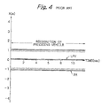
- FIG. 4 is a timing diagram of the first example of the operation of FIG. 3;
- FIG. 5 is a diagram illustrating a second example of the operation of the preceding vehicle recognizing apparatus of FIG. 1;
- FIG. 6 is a timing diagram of the second example of the operation of FIG. 5;
- FIG. 7 is a diagram illustrating a third example of the operation of the preceding vehicle recognizing apparatus of FIG. 1;
- FIGS. 8A, 8 B and 8 C are timing diagrams of the third example of the operation of FIG. 7;
- FIG. 9 is a block circuit diagram illustrating an embodiment of the preceding vehicle recognizing apparatus according to the present invention.
- FIG. 10 is a flowchart for explaining the operation of the preceding vehicle recognizing apparatus of FIG. 9 where the electronic control unit is constructed by a microcomputer;
- FIG. 11 is a first example of a detailed flowchart of step 1002 of FIG. 10;
- FIG. 12 is a timing diagram for explaining the flowchart of FIG. 11;
- FIG. 13 is a second example of a detailed flowchart of step 1002 of FIG. 10;
- FIG. 14 is a timing diagram for explaining the flowchart of FIG. 13;
- FIG. 15 is a third example of a detailed flowchart of step 1002 of FIG. 10;
- FIG. 16 is a timing diagram for explaining the flowchart of FIG. 14.
- FIGS. 17A and 17B are timing diagrams of examples of the operation of FIG. 9 .
- FIGS. 1, 2 , 3 , 4 , 5 , 6 , 7 8 A, 8 B and 8 C Before the description of the preferred embodiment, a prior art preceding vehicle recognizing apparatus will be explained with reference to FIGS. 1, 2 , 3 , 4 , 5 , 6 , 7 8 A, 8 B and 8 C.
- reference numeral 1 designates a preceding vehicle detecting sensor for detecting X- and Y-locations of a preceding vehicle PV (see FIGS. 3, 5 and 7 ).
- the preceding vehicle detecting sensor 1 is constructed by a scan laser radar including a semiconductor laser device.
- the preceding sensor 1 calculates a distance between the preceding vehicle PV and a vehicle V(see FIGS. 3, 5 and 7 ) on which the preceding vehicle recognizing apparatus of FIG.
- Reference numeral 2 designates a vehicle speed sensor for detecting a speed SPD of the vehicle V
- 3 designates a yaw rate sensor for detecting a rotational angular speed ⁇ of the vehicle V.
- the X- and Y-locations of the preceding vehicle PV of the preceding vehicle sensor 1 , the vehicle speed SPD of the vehicle speed sensor 2 and the rotational angular speed ⁇ of the yaw rate sensor 3 are supplied to an electric control unit (ECU) 4 .
- ECU electric control unit
- the electric control unit 4 is connected to a display unit 5 for displaying the X- and Y-locations of the preceding vehicle PV and a vehicle speed control unit 6 for controlling the speed of the vehicle so that the distance between the vehicle V and the preceding vehicle PV is brought close to a definite value.
- the electronic control unit 4 is constructed by a vehicle locus estimating section 41 , a preceding vehicle recognizing region setting section 42 and a preceding vehicle recognizing section 43 .
- the vehicle locus estimating section 41 receives the vehicle speed SPD of the vehicle speed sensor 2 and the rotational angular speed ⁇ of the yaw rate sensor 3 to estimate a locus of the vehicle V. That is, the vehicle locus estimating section 41 calculates a radius R of curvature of a lane on which the vehicle V is traveling, and estimates the vehicle locus in accordance with the vehicle speed SPD and the curvature radius R of the lane. Then, the preceding vehicle recognizing region setting section 42 sets a preceding vehicle recognizing region RR as shown in FIGS. 3, 5 and 7 in accordance with the estimated vehicle locus.
- the preceding vehicle recognizing section 43 determines whether or not the X- and Y-locations of the preceding vehicle PV are within the set preceding vehicle recognizing region RR. As a result, when the X- and Y-locations of the preceding vehicle PV are within the preceding vehicle recognizing region RR, the preceding vehicle PV is displayed on the display unit 5 , and the vehicle speed control unit 6 is operated. Otherwise, i.e., when the X- and Y-locations of the preceding vehicle PV is not within the preceding vehicle recognizing region RR, the display unit 5 and the vehicle speed control unit 6 are not operated.
- the electric control unit 4 can be constructed by a microcomputer including a central processing unit (CPU), a read-only memory (ROM), a random access memory (RAM) and the like. In this case, the electric control unit 4 is operated in accordance with a flowchart as illustrated in FIG. 2 which is started when the preceding vehicle detector 1 detects a preceding vehicle PV as a target.
- CPU central processing unit
- ROM read-only memory
- RAM random access memory
- the CPU calculates a curvature radius R of the vehicle V in accordance with the rotational angular speed ⁇ of the yaw rate sensor 3 .
- the CPU estimates a vehicle locus of the vehicle V in accordance with the vehicle speed SPD of the vehicle speed sensor 2 and the rotational angular speed ⁇ of the yaw rate sensor 3 .
- this preceding vehicle recognizing region is defined by two X-coordinates centered at a location of the vehicle V on the estimated vehicle locus at a timing when the vehicle V reaches the Y-location of the target preceding vehicle PV.
- the CPU determines whether or not the target preceding vehicle PV is within the preceding vehicle recognizing region, i.e., whether or not the X-location is within the above-mentioned two X-coordinates.
- the control proceeds to step 205 which establishes a recognition of the preceding vehicle to operate the display unit 5 and the vehicle speed control unit 6 .
- the control proceeds to step 206 which establishes no recognition of the preceding vehicle so that the display unit 5 and the vehicle speed control unit 6 are not operated.
- FIGS. 3, 4 , 5 , 6 , 7 , 8 A, 8 B and 8 C Examples of the operation of the preceding vehicle recognizing apparatus of FIG. 1 are explained next with reference to FIGS. 3, 4 , 5 , 6 , 7 , 8 A, 8 B and 8 C.
- FIG. 3 is a diagram where the target preceding vehicle PV continues traveling on the same lane on a non-curved expressway as the vehicle V.
- a preceding vehicle recognizing region RR for the target preceding vehicle PV is as shown in FIG. 4, and a locus LPV of the preceding vehicle PV keeps approximately centered at the preceding vehicle recognizing region RR. Thus, recognition of the preceding vehicle is maintained.
- FIG. 5 is a diagram where the target preceding vehicle PV is traveling on the same lane on a non-curved expressway as the vehicle V, and then, carries out a lane change.
- a preceding vehicle recognizing region RR for the target preceding vehicle PV is as shown in FIG. 5, and at timing t 1 , a locus LPV of the preceding vehicle PV is deviated from the preceding vehicle recognizing region RR. Thus, no recognition of the preceding vehicle is established after timing t 1 .
- FIG. 7 is a diagram where the target preceding vehicle continues traveling on the same lane on a curved expressway as the vehicle V.
- the vehicle V and the preceding vehicle PV are both traveling at a speed of 100 km/h.
- a preceding vehicle recognizing region RR for the target preceding vehicle PV is as shown in FIG. 8 A. That is, at timing t 1 , i.e., at about 1.5 sec, the vehicle V enters the curved expressway, to decrease the curvature radius R of the vehicle V, so that the preceding vehicle recognizing region RR is moved in the +X direction. However, since the target preceding vehicle PV is still in the preceding vehicle recognizing region RR, the recognition of the preceding vehicle is maintained.
- a preceding vehicle recognizing region RR for the target preceding vehicle PV is as shown in FIG. 8 B. That is, at timing t 1 , i.e., at about 2.6 sec, the vehicle V enters the curved expressway, to decrease the curvature radius R of the vehicle V, so that the preceding vehicle recognizing region RR is moved in the +X direction.
- timing t 2 i.e., at about 2.8 sec
- timing t 3 i.e., at about 3.8 sec
- the target preceding vehicle PV again enters the preceding vehicle recognizing region RR, so that recognition of the preceding vehicle is again established. Thereafter, the recognition of the preceding vehicle is maintained.
- a preceding vehicle recognizing region RR for the target preceding vehicle PV is as shown in FIG. 8 C. That is, at timing t 1 , i.e., at about 1.9 sec, when the target preceding vehicle PV is deviated from the preceding vehicle recognizing region RR, no recognition of the preceding vehicle is established.
- the vehicle V enters the curved expressway, to decrease the curvature radius R of the vehicle V, so that the preceding vehicle recognizing region RR is moved in the +X direction.
- timing t 3 i.e., at about 5.0 sec, the target preceding vehicle PV again enters the preceding vehicle recognizing region RR, so that recognition of the preceding vehicle is again established. Thereafter, the recognition of the preceding vehicle is maintained.
- the target preceding vehicle PV is excluded from the recognition of the preceding vehicle.
- the target preceding vehicle PV carries out a lane change despite the fact that the target preceding vehicle PV actually continues travelling on the same lane.
- a preceding vehicle recognizing operation may be performed upon another preceding vehicle for that time period, so that the vehicle speed control unit 6 would make the vehicle V follow after the other preceding vehicle.
- FIG. 9 which illustrates an embodiment of the preceding vehicle recognizing apparatus according to the present invention
- the electronic control unit 4 of FIG. 1 is modified into an electronic control unit 4 ′ which includes a modified preceding vehicle recognizing section 43 ′ instead of the preceding vehicle recognizing section 43 of FIG. 1, and a curved road determining section 44 .
- the curved road determining section 44 monitors the X-location of the preceding vehicle PV to determine whether or not an expressway on which the preceding vehicle PV is traveling is curved. For example, if the expressway is not curved, the vehicle V would have carried out a lane change or the like.
- the curved road determining section 44 is operated by the preceding vehicle recognizing section 43 ′ as set forth below.
- the preceding vehicle recognizing section 43 ′ operates the curved road determining section 44 without releasing the recognition of the preceding vehicle.
- the curved road determining section 44 determines whether or not the expressway on which the preceding vehicle PV is traveling is curved.
- the determination result of the curved road determining section 44 is supplied to the preceding vehicle recognizing section 43 ′.
- the preceding vehicle recognizing section 43 ′ releases the recognition of the preceding vehicle.
- the preceding vehicle recognizing section 43 ′ keeps determining whether or not the preceding vehicle PV is within the preceding vehicle recognizing region RR for a predetermined time period. As a result, when the preceding vehicle PV is within the preceding vehicle recognizing region RR for that predetermined time period, the recognition of the preceding vehicle is not released. On the other hand, when the preceding vehicle PV is never within the preceding vehicle recognizing region RR for that predetermined time period, the recognition of the preceding vehicle is released.
- the electronic control unit 4 ′ can also be constructed by a microcomputer. In this case, the electronic control unit 4 ′ is operated in accordance with a flowchart as illustrated in FIG. 10 . In FIG. 10, steps 1001 through 1006 are added to the steps of FIG. 2 .
- step 1001 determines whether or not the preceding vehicle PV is within the preceding vehicle recognizing region RR.
- step 1002 determines whether or not the expressway on which the preceding vehicle PV is traveling is curved.
- This curved road determination step 1002 sets a flag FX in accordance with whether or not the expressway on which the preceding vehicle PV is traveling is curved.
- the value “1” of the flag FX means a curved road, while the value “0” of the flag FX means a lane change. This will be explained later in detail with reference to FIGS. 11A, 11 B, 12 A, 12 B and 13 A, 13 B.
- step 206 the control proceeds to step 206 which establishes no recognition of the preceding vehicle, i.e., releases the recognition of the preceding vehicle.
- the predetermined time period T ext is experimentally defined.
- the predetermined time period T ext can depend upon the rotational angular speed ⁇ , i.e., the curvature radius R of the preceding vehicle PV. In this case, the smaller the curvature radius R, the longer the predetermined time period T ext .
- the predetermined time period T ext can depend upon the vehicle-between distance. In this case, the larger the vehicle-between distance, the longer the predetermined time period T ext .
- the control at step 1004 proceeds to steps 1005 and 1006 . That is, at steps 1005 and 1006 , it is determined whether or not the preceding vehicle PV is within the preceding vehicle recognizing region RR for the predetermined time period T ext . As a result, when the preceding vehicle PV enters the preceding vehicle recognizing region RR for the predetermined time period T ext , the control returns to step 205 , so that the recognition of the preceding vehicle is maintained. On the other hand, when the preceding vehicle PV has never entered the preceding vehicle recognizing region RR for the predetermined time period T ext , the control proceeds to step 206 which establishes no recognition of the preceding vehicle, i.e., releases the recognition of the preceding vehicle.
- step 1002 A first example of step 1002 is explained next with reference to FIGS. 11 and 12 .
- step 1101 it is determined whether or not a waiting time period T 1 has passed. Only when the waiting time period T 1 has passed, does the control proceed to step 1102 which initializes a value N, i.e.,
- step 1103 the X-location X of the preceding vehide PV is fetched, and at step 1104 ,
- step 1105 it is determined whether or not a determining time period T 2 has passed.
- the control proceeds to steps 1106 through 1110 .
- the control proceeds to steps 1111 through 1113 .
- Steps 1106 through 1110 are explained next.
- the X-location of the preceding vehicle PV is fetched.
- step 1107 it is determined whether or not a time period ⁇ t ( ⁇ T 2 ) such as 100 ms has passed. Only when the time period ⁇ t has passed, does the control proceed to step 1108 which calculates a difference ⁇ X of the X-location of the preceding vehicle PV by
- step 1109 it is determined whether or not an absolute value of ⁇ X is larger than a threshold value ⁇ X th , i.e.,
- ⁇ X th is a definite value corresponding to the width of a lane such 3.5 m plus a margin such as 1.5 m. Only when
- Steps 1111 through 1113 are explained next.
- step 1111 it is determined whether or not the value N is larger than a threshold value N th .
- N>N th the control proceeds to step 1112 which sets the flag FX, which means that the expressway on which the preceding vehicle PV is traveling is curved.
- step 1113 the control proceeds to step 1113 which resets the flag FX, which means that the preceding vehicle PV has carried out a lane change.
- control returns to step 1003 of FIG. 10 .
- step 1002 A second example of step 1002 is explained next with reference to FIGS. 13 and 14.
- step 1101 of FIG. 11 is deleted, and steps 1105 and 1111 of FIG. 11 are modified to steps 1105 ′ and 1111 ′, respectively.
- a value N is initialized, i.e.,
- step 1103 the X-location X of the preceding vehide PV is fetched, and at step 1104 ,
- step 1105 ′ it is determined whether or not a determining time period T 3 has passed.
- T 3 corresponds to T 1 +T 2 of FIGS. 11 and 12.
- the control proceeds to steps 1106 through 1110 .
- the control proceeds to steps 1111 ′ through 1113 .
- Steps 1106 through 1110 are explained next.
- the X-location of the preceding vehicle PV is fetched.
- step 1107 it is determined whether or not a time period ⁇ t ( ⁇ T 3 ) such as 100 ms has passed. Only when the time period ⁇ t has passed, does the control proceed to step 1108 which calculates a difference A X of the X-location of the preceding vehicle PV by
- step 1109 it is determined whether or not an absolute value of ⁇ X is larger than a threshold value A X th , i.e.,
- ⁇ X th is a definite value corresponding to the width of a lane such 3.5 m plus a margin such as 1.5 m. Only when
- Steps 1111 ′ through 1113 are explained next.
- step 1111 ′ it is determined whether or not the value N is larger than a threshold value N th ′.
- N th ′ is larger than N th of step 1111 of FIG. 11 .
- the control proceeds to step 1112 which sets the flag FX, which means that the expressway on which the preceding vehicle PV is traveling is curved.
- the control proceeds to step 1113 which resets the flag FX, which means that the preceding vehicle PV has carried out a lane change.
- control returns to step 1003 of FIG. 10 .
- step 1002 A third example of step 1002 is explained next with reference to FIGS. 15 and 16.
- step 1102 , 1103 , 1104 , 1110 and 1111 ′ of FIG. 13 is deleted.
- step 1105 ′ it is determined whether or not a determining time period T 3 has passed. Only when the determining time period T 3 has passed, does the control proceed to steps 1106 through 1109 , 1112 and 1113 .
- the X-location of the preceding vehicle PV is fetched as an intitial value X0.
- step 1107 it is determined whether or not a time period ⁇ t ( ⁇ T 3 ) such as 100 ms has passed. Only when the time period ⁇ t has passed, does the control proceed to step 1108 which calculates a difference ⁇ X of the X-location of the preceding vehicle PV by
- step 1109 it is determined whether or not an absolute value of ⁇ X is larger than a threshold value ⁇ X th , i.e.,
- ⁇ X th is a definite value corresponding to the width of a lane such 3.5 m plus a margin such as 1.5 m.
- the control proceeds to step 1112 which sets the flag FX, which means that the expressway on which the preceding vehicle PV is traveling is curved.
- the control proceeds to step 1113 which resets the flag FX, which means that the preceding vehicle PV has carried out a lane change.
- control returns to step 1003 of FIG. 10 .
- FIGS. 17A and 17B correspond to FIGS. 8B and 8C, respectively, of the prior art. Note that no problems occur in the cases as shown in FIGS. 4, 6 and 8 A.
- FIGS. 17A and 17B at timing t 1 , i.e., at about 2.6 sec, the vehicle V enters the curved expressway, to decrease the curvature radius R of the vehicle V, so that the preceding vehicle recognizing region RR is moved to the +V direction.
- timing t 2 i.e., at about 2.8 sec
- the target preceding vehicle PV is deviated from the preceding vehicle recognizing region RR, so that a curved road determination is carried out while the recognition of the preceding vehicle is maintained.
- timing t 3 it is determined that the expressway on which the preceding vehicle PV is traveling is curved
- a predetermined time period T ext from timing t 3 to timing t 4 is set to determine whether the preceding vehicle PV is within the preceding vehicle recognizing region RR.
- the recognition of the preceding vehicle is maintained even when the preceding vehicle PV is deviated from the preceding vehicle recognizing region RR due to the curved expressway.
- the preceding vehicle recognizing apparatus can be applied to an auto cruise control (ACC) of a vehicle, to make it smooth.
- ACC auto cruise control
Landscapes
- Physics & Mathematics (AREA)
- Engineering & Computer Science (AREA)
- Computer Networks & Wireless Communication (AREA)
- Electromagnetism (AREA)
- General Physics & Mathematics (AREA)
- Radar, Positioning & Navigation (AREA)
- Remote Sensing (AREA)
- Traffic Control Systems (AREA)
- Control Of Driving Devices And Active Controlling Of Vehicle (AREA)
- Radar Systems Or Details Thereof (AREA)
- Optical Radar Systems And Details Thereof (AREA)
- Controls For Constant Speed Travelling (AREA)
Abstract
Description
Claims (21)
Applications Claiming Priority (2)
| Application Number | Priority Date | Filing Date | Title |
|---|---|---|---|
| JP2001-022315 | 2001-01-30 | ||
| JP2001022315A JP4113334B2 (en) | 2001-01-30 | 2001-01-30 | Prior vehicle recognition method and apparatus |
Publications (2)
| Publication Number | Publication Date |
|---|---|
| US20020103600A1 US20020103600A1 (en) | 2002-08-01 |
| US6629036B2 true US6629036B2 (en) | 2003-09-30 |
Family
ID=18887751
Family Applications (1)
| Application Number | Title | Priority Date | Filing Date |
|---|---|---|---|
| US10/061,056 Expired - Lifetime US6629036B2 (en) | 2001-01-30 | 2002-01-29 | Method and apparatus for recognizing preceding vehicle with determination of curved traffic lane |
Country Status (3)
| Country | Link |
|---|---|
| US (1) | US6629036B2 (en) |
| EP (1) | EP1227339A3 (en) |
| JP (1) | JP4113334B2 (en) |
Cited By (2)
| Publication number | Priority date | Publication date | Assignee | Title |
|---|---|---|---|---|
| US20030234127A1 (en) * | 2002-06-19 | 2003-12-25 | Nissan Motor Co., Ltd. | Adaptive cruise control system |
| US6744380B2 (en) * | 2001-10-10 | 2004-06-01 | Denso Corporation | Apparatus for monitoring area adjacent to vehicle |
Families Citing this family (4)
| Publication number | Priority date | Publication date | Assignee | Title |
|---|---|---|---|---|
| JP4163074B2 (en) * | 2003-08-25 | 2008-10-08 | 富士重工業株式会社 | Vehicle driving support device |
| US8451139B2 (en) * | 2010-02-22 | 2013-05-28 | Cnh America Llc | System and method for coordinating harvester and transport vehicle unloading operations |
| JP6413479B2 (en) * | 2014-08-22 | 2018-10-31 | 株式会社アドヴィックス | Vehicle control device |
| JP6363517B2 (en) * | 2015-01-21 | 2018-07-25 | 株式会社デンソー | Vehicle travel control device |
Citations (5)
| Publication number | Priority date | Publication date | Assignee | Title |
|---|---|---|---|---|
| US4757450A (en) * | 1985-06-03 | 1988-07-12 | Nissan Motor Company, Limited | Method and system for automatically detecting a preceding vehicle |
| US5633642A (en) | 1993-11-23 | 1997-05-27 | Siemens Aktiengesellschaft | Radar method and device for carrying out the method |
| EP0928714A2 (en) | 1998-01-08 | 1999-07-14 | Nissan Motor Co., Ltd. | Automatic speed control device for regulation of vehicle spacing |
| US6011507A (en) | 1996-11-12 | 2000-01-04 | Raytheon Company | Radar system and method of operating same |
| US6265990B1 (en) * | 1998-07-17 | 2001-07-24 | Denso Corporation | Apparatus and method for controlling a distance between two traveling vehicles and a recording medium for storing the control method |
-
2001
- 2001-01-30 JP JP2001022315A patent/JP4113334B2/en not_active Expired - Fee Related
-
2002
- 2002-01-29 EP EP02002207A patent/EP1227339A3/en not_active Withdrawn
- 2002-01-29 US US10/061,056 patent/US6629036B2/en not_active Expired - Lifetime
Patent Citations (5)
| Publication number | Priority date | Publication date | Assignee | Title |
|---|---|---|---|---|
| US4757450A (en) * | 1985-06-03 | 1988-07-12 | Nissan Motor Company, Limited | Method and system for automatically detecting a preceding vehicle |
| US5633642A (en) | 1993-11-23 | 1997-05-27 | Siemens Aktiengesellschaft | Radar method and device for carrying out the method |
| US6011507A (en) | 1996-11-12 | 2000-01-04 | Raytheon Company | Radar system and method of operating same |
| EP0928714A2 (en) | 1998-01-08 | 1999-07-14 | Nissan Motor Co., Ltd. | Automatic speed control device for regulation of vehicle spacing |
| US6265990B1 (en) * | 1998-07-17 | 2001-07-24 | Denso Corporation | Apparatus and method for controlling a distance between two traveling vehicles and a recording medium for storing the control method |
Cited By (3)
| Publication number | Priority date | Publication date | Assignee | Title |
|---|---|---|---|---|
| US6744380B2 (en) * | 2001-10-10 | 2004-06-01 | Denso Corporation | Apparatus for monitoring area adjacent to vehicle |
| US20030234127A1 (en) * | 2002-06-19 | 2003-12-25 | Nissan Motor Co., Ltd. | Adaptive cruise control system |
| US6985805B2 (en) * | 2002-06-19 | 2006-01-10 | Nissan Motor Co., Ltd. | Adaptive cruise control system |
Also Published As
| Publication number | Publication date |
|---|---|
| JP4113334B2 (en) | 2008-07-09 |
| US20020103600A1 (en) | 2002-08-01 |
| EP1227339A2 (en) | 2002-07-31 |
| JP2002228748A (en) | 2002-08-14 |
| EP1227339A3 (en) | 2003-07-09 |
Similar Documents
| Publication | Publication Date | Title |
|---|---|---|
| US6990216B2 (en) | Method and apparatus for estimating inter-vehicle distance using radar and camera | |
| US6114973A (en) | Method and apparatus for recognizing whether traffic drives on the right or on the left | |
| US7042389B2 (en) | Device for detecting object in front of vehicle | |
| US7650217B2 (en) | Adaptive cruise control system and navigation system's media with vehicle control information included | |
| US5926126A (en) | Method and system for detecting an in-path target obstacle in front of a vehicle | |
| US7782179B2 (en) | Obstacle detection apparatus | |
| US6795765B2 (en) | Tracking of a target vehicle using adaptive cruise control | |
| US6794987B2 (en) | Object detection system and method of estimating object size | |
| EP1256784A2 (en) | Car navigation apparatus capable of determining entry into parking area | |
| US20030011509A1 (en) | Method for detecting stationary object on road | |
| US6636148B2 (en) | Periphery monitoring system | |
| US11377145B2 (en) | Vehicle control device and control method for vehicle | |
| JP2001099930A (en) | Sensor for monitoring periphery | |
| US8165797B2 (en) | Vehicular control object determination system and vehicular travel locus estimation system | |
| US6691018B1 (en) | Method and system for identifying a lane change | |
| US6600986B2 (en) | Method for the longitudinal control of a vehicle in which information of a navigation system is detected | |
| EP1367410A2 (en) | Collision detection system and method of estimating miss distance employing curve fitting | |
| US6629036B2 (en) | Method and apparatus for recognizing preceding vehicle with determination of curved traffic lane | |
| US20230008630A1 (en) | Radar device | |
| JP2002175599A (en) | Lane position estimating device for precedent vehicle or target | |
| JP3355947B2 (en) | Preceding car tracking device | |
| JP2000180537A (en) | Method for identifying target to be controlled of scan- type radar | |
| JP2004082912A (en) | Inter-vehicle distance measuring device | |
| JP2002148336A (en) | Interruption prediction device | |
| JP3209671B2 (en) | Curved road judgment device |
Legal Events
| Date | Code | Title | Description |
|---|---|---|---|
| AS | Assignment |
Owner name: NEC CORPORATION, JAPAN Free format text: ASSIGNMENT OF ASSIGNORS INTEREST;ASSIGNOR:HIRAO, MANABU;REEL/FRAME:012572/0390 Effective date: 20020123 |
|
| AS | Assignment |
Owner name: HONDA ELESYS CO., LTD., JAPAN Free format text: ASSIGNMENT OF ASSIGNORS INTEREST;ASSIGNOR:NEC CORPORATION;REEL/FRAME:013935/0878 Effective date: 20021028 |
|
| STCF | Information on status: patent grant |
Free format text: PATENTED CASE |
|
| CC | Certificate of correction | ||
| FEPP | Fee payment procedure |
Free format text: PAYER NUMBER DE-ASSIGNED (ORIGINAL EVENT CODE: RMPN); ENTITY STATUS OF PATENT OWNER: LARGE ENTITY Free format text: PAYOR NUMBER ASSIGNED (ORIGINAL EVENT CODE: ASPN); ENTITY STATUS OF PATENT OWNER: LARGE ENTITY |
|
| FPAY | Fee payment |
Year of fee payment: 4 |
|
| FPAY | Fee payment |
Year of fee payment: 8 |
|
| FPAY | Fee payment |
Year of fee payment: 12 |