US6546464B2 - Method and apparatus for increasing data rates in a data network while maintaining system coherency - Google Patents
Method and apparatus for increasing data rates in a data network while maintaining system coherency Download PDFInfo
- Publication number
- US6546464B2 US6546464B2 US09/228,003 US22800399A US6546464B2 US 6546464 B2 US6546464 B2 US 6546464B2 US 22800399 A US22800399 A US 22800399A US 6546464 B2 US6546464 B2 US 6546464B2
- Authority
- US
- United States
- Prior art keywords
- coherency
- data
- memory
- cache lines
- processor
- Prior art date
- Legal status (The legal status is an assumption and is not a legal conclusion. Google has not performed a legal analysis and makes no representation as to the accuracy of the status listed.)
- Expired - Fee Related
Links
Images


Classifications
-
- G—PHYSICS
- G06—COMPUTING; CALCULATING OR COUNTING
- G06F—ELECTRIC DIGITAL DATA PROCESSING
- G06F12/00—Accessing, addressing or allocating within memory systems or architectures
- G06F12/02—Addressing or allocation; Relocation
- G06F12/08—Addressing or allocation; Relocation in hierarchically structured memory systems, e.g. virtual memory systems
- G06F12/0802—Addressing of a memory level in which the access to the desired data or data block requires associative addressing means, e.g. caches
- G06F12/0806—Multiuser, multiprocessor or multiprocessing cache systems
- G06F12/0815—Cache consistency protocols
- G06F12/0837—Cache consistency protocols with software control, e.g. non-cacheable data
Definitions
- the present invention relates to the field of data networking and, in particular, to a method and apparatus for increasing data rates in a data network while maintaining system coherency.
- Data networks come in many different sizes and network topologies. From small peer-to-peer networks enabling multiple users of a small office to share data, to more formal local area networks (LAN), wide-area and global data networks (i.e., the Internet). As reliance on such computer networks has increased, so too has the data traffic and congestion experienced on such networks.
- LAN local area networks
- Internet global data networks
- a lot of congestion occurs within the network devices used as network routing or switching points within the network core, e.g., routers, switches, bridges and the like.
- One reason for such congestion is the processing associated with the routing or switching decisions which are made, typically, on a frame by frame basis. That is, data packets are received and stored in a packet buffer(s) (e.g., system memory), analyzed and forwarded based on routing information contained within the packet, e.g., destination node address, as well as other network routing criteria, e.g., load balancing considerations.
- Another reason for the congestion is that many prior art input/output (I/O) busses are not optimized for network switching applications. As network traffic has increased, so too has the pressure to alleviate the bottlenecks associated with “core congestion”, i.e., the congestion caused by devices in the network core.
- a necessary first step in alleviating the core congestion was to increase the number and processing capability of processors in core devices, thereby creating a multiprocessor environment in the network core devices.
- processors in core devices
- system coherency increases the complexity of the data management required, often referred to as system coherency. That is, when multiple processors have access to common memory space, steps must be taken to ensure that the data retrieved from a memory space is still valid data.
- prior art network devices relied on either hardware or software approaches to maintaining system coherency for data stored within the common data packet buffers.
- the move to multiprocessing system with either hardware or software methods for maintaining system coherency incrementally improved the congestion experienced at network nodes, such improvement was short-lived. That is, traffic over data networks is constantly increasing thus requiring new and improved network devices to manage such data and alleviate congestion bottlenecks.
- an apparatus comprising system memory and a cache memory maintain system coherency for data stored in a subset of memory elements utilizing software coherency control, while system coherency for all remaining memory elements is maintained utilizing hardware coherency control.
- FIG. 1 illustrates a block diagram of a network device incorporating the teachings of the present invention in accordance with one embodiment of the present invention
- FIG. 2 including FIGS. 2A, 2 B and 2 C, illustrates a block diagram of an example cache memory denoting cache lines and a tag buffer suitable for use in accordance with the teachings of the present invention
- FIG. 3 illustrates a flow chart of an example method for maintaining system coherency of packet data, in accordance with one embodiment of the present invention
- FIG. 4 illustrates a block diagram of an example input/output bus interface incorporating the teachings of the present invention, in accordance with one embodiment of the present invention
- FIG. 5 illustrates a flow chart of an example method for controlling and optimizing the bandwidth of an input/output bus incorporating the teachings of the present invention, in accordance with one embodiment of the present invention
- FIGS. 6A and 6B graphically illustrate example signal diagrams for DMA transmit and receive operations, respectively, while operating in a multi-channel mode of operation, in accordance with one embodiment of the present invention
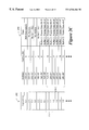
- FIG. 7 graphically illustrates an example signal diagram for bus control while operating in a single channel mode of operation, in accordance with one embodiment of the present invention
- FIG. 8 graphically illustrates an example signal diagram associated with the flow control provisions of the present invention, in accordance with one embodiment of the present invention.
- FIG. 9 illustrates a block diagram of an example data network within which the teachings of the present invention may be practiced.
- the present invention may be applicable to implementations of the invention in integrated circuits or chip sets, wireless implementations, switching systems products and transmission systems products.
- switching systems products shall be taken to mean private branch exchanges (PBXs), central office switching systems that interconnect subscribers, toll/tandem switching systems for interconnecting trunks between switching centers, and broadband core switches found at the center of a service provider's network that may be fed by broadband edge switches or access multiplexers, and associated signaling, and support systems and services.
- PBXs private branch exchanges
- central office switching systems that interconnect subscribers
- toll/tandem switching systems for interconnecting trunks between switching centers
- broadband core switches found at the center of a service provider's network that may be fed by broadband edge switches or access multiplexers, and associated signaling, and support systems and services.
- transmission systems products shall be taken to mean products used by service providers to provide interconnection between their subscribers and their networks such as loop systems, and which provide multiplexing, aggregation and transport between a service provider's switching systems across the wide area, and associated signaling and support systems and services.
- cache line or cache block
- a cache line should be thought of simply as the basic unit of coherency, irregardless of the memory space referenced.
- a cache line is 32 bytes long, while in alternate embodiments a cache line is 64 bytes, 128 bytes, 256 bytes, or any multiple thereof, long.
- reference will be made to cache lines within system memory 108 which simply references blocks of memory within system memory 108 which are a cache line long.
- FIG. 1 a block diagram of an example network device incorporating the teachings of the present invention is provided.
- network device 100 is shown comprising one or more processor modules 102 , one or more input/output (I/O) link modules 104 and an I/O bus 106 , communicatively coupled as shown.
- processor modules 102 selectively cache frames at processor(s) 114 (or associated cache 110 ), based on the type of frame, and maintain system coherency utilizing an innovative protocol that relies on software coherency for certain elements of the memory space, while relying on hardware coherency for other elements of the memory space.
- processor modules 102 incorporating the teachings of the present invention utilize software coherency control to maintain the coherency of the so-called “well known cache lines” of a frame, which must be accessed by a processor when processing a frame, and utilize hardware coherency control to maintain the coherency of all remaining cache lines, which a processor may or may not need to access to appropriately process the frame.
- processor module 102 to (a) maintain system coherency with a minimum number of time consuming cache block invalidate (e.g., kill) operations, and (b) perform the majority of kill operations under software coherency control, which requires less core bus cycles than do the bus kill operations associated with hardware coherency control.
- cache block invalidate e.g., kill
- network device 102 also includes an innovative bandwidth optimized input/output (I/O) bus 106 and associated protocol facilitating a high performance memory system with low latency.
- I/O input/output
- teachings of the present invention represents a new paradigm in core network device technology, enabling network devices to route data packets at a much faster rate alleviating the congestion often associated with prior art network devices.
- I/O module(s) 104 interface network device 100 to network A and network B. Although I/O module(s) 104 is depicted comprising only register 122 , those skilled in the art will appreciate that I/O module 104 may well contain other elements such as, for example, buffers, DMA devices, bus controller(s), programmable logic arrays (PLA's), processor(s) and the like. In accordance with the illustrated example embodiment, register 122 is used to stage packets to be transferred to another module within network device 100 , e.g., processor module(s) 102 .
- I/O module(s) 104 communicate with other network device modules through an innovative bandwidth optimized I/O bus 106 which improves the data transfer rate between and among network device modules, e.g., processor module(s) 102 .
- processor module 102 is shown comprising an input/output register 120 , system memory 108 , direct memory access (DMA) device(s) 116 , memory controller 118 , processor(s) 114 with associated cache(s) 110 and tag buffer 112 , each communicatively coupled as depicted.
- system memory 108 , DMA devices 116 and memory controller 118 are intended to represent any of a number of commonly available memory types, DMA devices and memory controllers, respectively, known in the art.
- system memory 108 is comprised of static random access memory (SRAM), dynamic random access memory (DRAM), or combinations thereof.
- system memory 108 is comprised of magnetic media such as, for example, a hard disk drive, a tape drive, a rewritable compact disk (CD), a digital versatile disk (DVD) and the like.
- Memory controller 118 is employed to control access to system memory 108 by, in particular, remote devices. In certain embodiments, memory controller 118 monitors the state of data stored within system memory 108 .
- DMA devices 116 utilize direct “channels” to access data in system memory 108 , without having to go through processor(s) 114 or memory controller 118 .
- system memory technology, memory controllers and DMA devices are each relatively well known and, as such, they need not be further described here.
- processor(s) 114 are intended to represent a broad range of processing devices including, but not limited to, a microcontroller, a microprocessor, an application specific integrated circuit (ASIC), a programmable logic array (PLA), and the like.
- processor(s) 114 are superscalar processors.
- processor 114 with tag buffer 112 may well include cache 110 within the processor package.
- processor(s) 114 may well have cache within and outside of the processor package.
- tag buffer 112 may well reside outside of the processor package.
- processor module(s) 102 utilize a processor cache, e.g., cache 110 to selectively cache frames based, in part, on the type of frame. That is, only those cache lines of frames which must be interpreted by processor 114 to appropriately route or process the frame are accessed by processor 114 and, thus, cached. All remaining frames are routed from system memory. Accordingly, those skilled in the art will appreciate that the innovative system coherency model, described herein, optimally manages the data in system memory 108 and cache memory 110 , only caching those frames which must be interpreted by processor(s) 114 , and forwarding the remaining frames after analyzing only the well known cache lines within the frame.
- packet data is tagged in system memory 108 at cache line granularities.
- tag buffer 112 which maintains the tag entries for the system memory 108 .
- the tag entries may be maintained as within the cache line entry itself say, for example, as a certain number of least significant bits of the entry.
- the tag associated with the cache line defines the coherency protocol that has been defined for that cache line and, as will be described below, depends on the nature of the content of the cache line.
- system coherency is maintained through an innovative hardware/software approach, wherein the method of coherency control is defined on a per cache line basis based, at least in part, on the type and/or content of the cache line.
- software coherency control is employed for the so-called “well known cache lines”, while hardware coherency control is utilized for all remaining cache lines.
- the well known cache lines are those cache lines which contain information denoting the type and destination of the frame, e.g., link list information associated with the operating system (GLL), Internet Protocol (IP) addresses, DMA descriptors, and the like.
- a tag in tag buffer 112 associated with the cache line will be modified to indicate that the data has been placed in cache 110 .
- an invalidate operation is issued to the processor's cache controller (not shown) to denote that the cache line in cache 110 is invalid (unreliable data), which forces subsequent processor accesses to the cache line to retrieve a “new” copy from system memory 108 .
- a tag entry (coherency encoding) of 0,0 denotes No Access.
- a coherency encoding of 0,0 is typically used within the context of the present invention as a spacer between buffers, thereby preventing overrun from the end of one buffer to the beginning of another buffer.
- a coherency encoding of 0,1 in a tag entry denotes that the cache line assocaited with the tag entry is subject to software coherency control. That is, the processor, e.g., processor(s) 114 , is responsible for maintaining coherency of cache lines with an associated tag entry of 0,1 by never accessing the cache line, or by issuing an invalidate instruction (also referred to as a kill operation) before accessing the cache line.
- an invalidate instruction also referred to as a kill operation
- the nomenclature of such an invalidate instruction necessarily varies from one processor architecture to another.
- processor(s) 114 issue a data cache block invalidate (dcbi) instruction which invalidates the appropriate cache line upon access by the processor.
- dcbi data cache block invalidate
- software kill operations take less clock cycles than hardware kill operations.
- only the well known cache lines are subject to software coherency control.
- a coherency encoding of 1,0 denotes that the coherency of the associated cache line is maintained by hardware.
- a cache block invalidate e.g., a bus kill operation
- the coherency encoding associated with the cache line is changed to a 1,1 as soon as the bus kill operation is posted.
- a coherency encoding of 1,1 denotes that hardware is responsible for maintaining the coherency associated with this cache line.
- FIG. 2A depicts an example memory space 200 and associated tag buffer 202 .
- memory space 200 represents system memory 108 .
- memory space 200 represents cache memory 110 .
- tag buffer 202 represents tag buffer 112 of processor module 102 .
- memory space 200 is shown partitioned on a cache line basis.
- memory space 200 is shown comprising three columns, one each for a memory address 204 , cache line number 206 and the data 208 .
- a cache line would merely contain a memory address space 204 and data space 208 .
- tag buffer 202 comprises a number of 2 bit registers 212 , 216 , etc., each associated with a particular cache line, e.g., 210 , 214 , etc., respectively.
- each tag buffer register is populated with the coherency encoding associated with each cache line of memory space 200 based, at least in part, on the content of the cache line.
- cache line 0 210 contains DMA descriptors.
- a coherency encoding of 0,1 is entered within tag buffer register 212 .
- Cache line 1 214 is used to separate buffers and, thus, has a coherency encoding of 0,0 in tag buffer register 216 associated with cache line 214 .
- cache lines 218 denote the start of a buffer entry, “Buffer 1 ”.
- the first cache line of Buffer 1 contains information associated with the link list employed by the operating system (GLL).
- the next two cache lines (64 bytes) contain media access control (MAC) and IP header information.
- MAC media access control
- the first three cache lines 218 of Buffer 1 are the well known cache lines and are, in accordance with the innovative system coherency protocol of the present invention, subject to software coherency control. Accordingly, tag buffer registers 220 associated with the three well known cache lines 218 are denoted with coherency encodings of 0,1.
- cache lines 218 Following the three well known cache lines 218 are a number of cache lines containing frame data which, depending on the content of the three well known cache lines, may or may not be accessed by processor 114 and, are therefore, subject to hardware coherency control. As shown, a single cache line with associated coherency encoding of 0,0 is used to separate Buffer 1 from Buffer 2 , with associated coherency encodings reflecting the nature of the content of the corresponding cache lines.
- FIG. 3 illustrates a flow chart of an example method for maintaining system coherency for a network device employing processor based forwarding of network data.
- the teachings of this aspect of the present invention will be developed in the context of an example application with reference to Buffer 2 presented in FIGS. 2A through 2C.
- the method begins at 302 wherein processor(s) 114 access the well known cache lines (i.e., cache lines d, e and f) of Buffer 2 .
- the well known cache lines are subject to software coherency control of the processor and, as a result have a coherency encoding of 0,1 in their respective tag registers.
- processor 114 issues a kill instruction (e.g., the dcbi instruction) and then reads the content of the cache line.
- processor 114 has accessed and invalidated the three well known cache lines, a determination is made as to whether processor 114 need access the remaining cache lines of the frame in order to appropriately process the frame, block 304 . As provided above, processor 114 makes the determination of whether the remaining cache lines of the frame must be accessed based on the nature of the frame, i.e., whether the frame must be interpreted by, or merely forwarded by network device 102 .
- processor 114 determines from the well known cache lines that the frame is intended for another network device, the frame is forwarded without touching the remaining cache lines of the buffer, block 306 . That is, processor 114 identifies the type and intended destination node from the well known cache lines and need not access the remaining cache lines. Since the remaining cache lines are subject to hardware coherency control, and were not accessed by processor 114 the coherency encodings associated with these cache lines remain unchanged until Buffer 2 is freed and new data is written to the cache lines of Buffer 2 , block 308 .
- processor 114 accesses the remaining cache lines of Buffer 2 , block 310 .
- processor 114 accesses the remaining cache lines of Buffer 2 , it is assumed that these cache lines are now stored in processor cache 110 . Accordingly, the coherency encoding for these cache lines are updated to reflect that the contents of the cache lines are also stored in cache memory 110 , block 312 , as the cache lines associated with Buffer 2 are freed. In accordance with the protocol presented above in Table 1, the coherency encodings for these cache lines are updated to reflect shared hardware coherency control 1,0, as reflected in FIG. 2 B.
- the coherency encoding of tag registers 228 associated with the remaining cache lines 226 of Buffer 2 are modified from the 1,1 depicted in FIG. 2A to 1,0 as depicted in FIG. 2 B.
- the coherency encoding associated with remaining cache lines 226 of Buffer 2 remaining until, in block 314 , the remaining cache lines are accessed.
- FIG. 2C provides an example wherein Buffer 2 receives 128 bytes of data, thus extending into the first two cache lines 230 of the remaining cache lines of Buffer 2 . Accordingly, tag registers 232 associated with these modified cache lines 230 of Buffer 2 are updated to reflect hardware coherency control 1,1.
- a bus kill instruction is issued by the FSM of the memory controller to processor 114 , which accepts the instruction during a snoop phase and the lines within cache 110 associated with the modified cache lines 230 in system memory 200 are changed from an exclusive status (e.g., data valid) to an invalid status, block 318 .
- FIG. 4 illustrates a circuit diagram of a bandwidth optimized I/O bus 106 of FIG. 1 which employs an innovative control protocol facilitating direct memory access I/O transfers between network device modules, e.g., processor modules 102 and I/O link modules 104 .
- network device modules e.g., processor modules 102 and I/O link modules 104 .
- I/O bus 106 is configured and controlled to facilitate data transfers along one or more dynamically provisioned virtual channels.
- optimized I/O bus 106 is dynamically configured and controlled to facilitate data transmission along a single virtual channel at a first time, and as a plurality of channels at a second time. That is, I/O bus 106 and associated protocol provide a dynamically configurable means of supporting high capacity, low latency DMA transfers of data, heretofore unavailable in the networking arts in support of the innovative memory system described above. Although depicted and described in association with communication between processor modules and link modules, those skilled in the art will appreciate that the teachings of the present invention are transferable to any bus environment.
- processor module 102 is shown coupled to I/O link module 104 via the innovative bandwidth optimized I/O bus 106 .
- Registers 402 - 412 of processor module 102 are cumulatively referenced as register 120 in FIG. 1, while registers 414 - 424 are cumulatively referenced as register 122 in FIG. 1 .
- registers are well known by those skilled in the art and, thus, need not be further described here.
- I/O bus 106 utilizes four (4) synchronous DMA control signals DMA REQ_OUT [ 1 : 0 ] 430 , and DMA REQ_IN [ 1 : 0 ] 431 to dynamically provision bandwidth and control data transfer between link module 104 and processor module 102 over bandwidth optimized I/O bus 106 .
- DMA control signals 430 and 431 are utilized to signal transmit queries and responses between network device modules, e.g., processor module 102 and link module 104 , and link modules, and to determine which DMA channels are available and to be used for data transfer.
- the query/response protocol is designed to occur concurrently with data transfer.
- next iteration transmit or receive
- the bandwidth provisioning and data control of I/O bus operate in accordance with a protocol designed around a query/response paradigm.
- control of the bus is performed through transmit request queries and associated responses sent via REQ_OUT 430 and REQ_IN 431 .
- each query is responded to, irregardless of whether the responding module can authorize the requested action. For example, a transmit query for each channel must be affirmatively responded to before transmission along that channel may begin.
- REQ_OUT 430 and REQ_IN 431 alternate between servicing channels in the transmit and receive directions, i.e., through time division multiplexing.
- a period of time during which all serviceable transmit channels are managed is called the transmit iteration.
- a receive iteration is the period in which all serviceable receive channels are accommodated.
- a response is only generated when the requested action is authorized.
- a DMA transmit request query cycle is initiated by processor module 102 driving REQ_OUT [ 1 ] LOW and REQ_OUT [ 0 ] HIGH for one clock cycle.
- the next two clock cycles are used to multiplex the transmit status of the four DMA channels, i.e., bandwidth requested, from processor module 102 to link module 104 .
- REQ_OUT [ 0 ] is used in successive clock cycles to denote the transmit status of channels 0 and 2
- REQ_OUT [ 1 ] is used in successive clock cycles to denote the transmit status of channels 1 and 3 .
- driving the appropriate REQ_OUT line to LOW indicates a valid transmit buffer is available and awaiting data transmission on the channel represented by the time-division slot.
- the following DMA transmit request query denotes that processor module 102 has data to transmit on all four channels of a four-channel I/O bus 106 :
- REQ_OUT [ 1 ] is driven low to indicate a request query, while REQ_OUT [ 0 ] indicates the type of request query (high denotes transmit while low denotes receive).
- the status of each of the channels of the multi channel bus is presented (low denotes available).
- the requested bandwidth i.e., the status of each of the channels of the bus
- the above example denotes a transmit request with data available for transmission on all four channels of a four channel bus.
- link module 104 When link module 104 receives a transmit query request, in accordance with one embodiment of the query/response paradigm, a response cycle on REQ_IN [ 1 : 0 ] 431 is generated.
- link module 104 drives REQ_IN [ 1 ] low to denote a response cycle, while REQ_IN [ 0 ] remains HIGH to denote a transmit response cycle.
- the state of each REQ_IN [ 1 : 0 ] line denotes which channels are available on link module 104 to accept data for transmission.
- REQ_IN[ 1 ] is associated with channels 0 and 2
- REQ_IN[ 0 ] is associated with channels 1 and 3 .
- the following transmit response denotes that link module 104 has bandwidth available to accept data on all four channels of four-channel I/O bus 106 :
- REQ_IN [ 1 ] driven low is indicative of a response
- REQ_IN [ 0 ] driven high indicates the type of response (high denotes transmit while low denotes receive).
- the status of each of the channels of the multi channel bus is presented (low denotes available).
- link module 104 is available to accept data for transmission on all four channels of a four-channel I/O bus 106 .
- bandwidth optimized I/O bus 106 Having introduced the architectural elements and the control protocol of bandwidth optimized I/O bus 106 , above, an example method of operation will be provided with reference to the flow chart of FIG. 5, and the signaling diagrams of FIGS. 6-8. For ease of explanation, and not limitation, the operation of the bandwidth optimized I/O bus 106 and associated control protocol will be described with continued reference to FIGS. 1 and 4.
- I/O bus 106 may operate in one of two modes, e.g., single channel mode or a multi-channel mode based, at least in part, on the bandwidth requirements of the communicating modules. Accordingly, the method of FIG. 5 begins, a block 502 with a determination of whether the I/O bus 106 is to operate in single or multi-channel mode. If, in block 502 , it is determined that multi-channel mode is preferred or required, I/O bus 106 awaits a request for a receive or transmit iteration from one of the modules (e.g., processor module or link module) in block 504 .
- the modules e.g., processor module or link module
- the modules Upon receipt of such a request, the modules negotiate the bandwidth requirements for the communication, block 506 .
- the negotiation is carried out between the modules via the query/response protocol of REQ_OUT and REQ_IN.
- the modules identify which channels, if any, are available for the transfer of data. Once the determination has been as to which communication channels are available, the transfer of data may commence on the selected communication channels, subject to the flow control provisions of I/O bus 106 to be described more fully below, block 508 . Transfer of data continues, in block 510 , until an indication of the last burst (BLAST) is received.
- BLAST last burst
- FIGS. 6A and 6B examples of data transfer in accordance with a transmit iteration and a response iteration in a multi-channel mode of an I/O bus incorporating the teachings of the present invention will be presented with reference to FIGS. 6A and 6B, respectively.
- the signaling depicted in adjacent steps in the following figures is not intended to represent adjacent clock cycles. That is, as with any hardware interface, the speed at which communication between two modules occurs depends on the inherent latencies associated with the physical position and location of the modules. Thus, while signaling in FIGS. 6A and 6B may appear to occur in immediately adjacent steps, those skilled in the art will appreciate that it may well require several clock cycles for the signals to actually propagate between the network device modules.
- FIG. 6A a transmit request cycle in multi channel mode is depicted, wherein control and status signals corresponding to each of the four DMA channels of I/O bus 106 are controlled on a time division basis.
- FIG. 6A illustrates the status of REQ_OUT [ 1 : 0 ] 430 signal line, REQ_IN [ 1 : 0 ] 431 signal line, DMA burst control line 434 , DMA blast control line 436 , and DMA data bus [ 31 : 0 ] 432 to transmit data to up to multiple DMA channels in a time division manner.
- control signals are inactive (denoted by both control lines of REQ_OUT 430 and REQ_IN 431 being driven to a high state HH) during cycles 602 and 604 .
- a DMA transmit query signal is issued by processor module 102 over REQ_OUT[ 1 : 0 ] 430 denoting a transmit operation, e.g., REQ_OUT [ 1 ] is Low denoting a query, and REQ_OUT [ 0 ] is High denoting a transmit query.
- processor module denotes which channels over which it has data to transfer, in accordance with the protocol described above.
- link module 104 acknowledges receipt of the transmit query with a transmit response, e.g., REQ_IN [ 1 ] is low (response), while REQ_IN [ 0 ] is high (transmit operation).
- link module 104 receives the bandwidth request (e.g., the channels for which processor module would like to transfer data) from processor module 102 via REQ_OUT [ 1 : 0 ] 430 .
- link module 104 acknowledges its ability to accept data via at least one of the requested data channels by issuing a transmit response via REQ_IN 431 , in accordance with the protocol described above.
- any response/query iteration may have 0, 1, 2, 3 or 4 channels serviced, as negotiated between processor module 102 and link module 104 over REQ_OUT 430 and REQ_IN 431 .
- DMA burst control line 434 is driven low enabling data transfer to commence to at least one DMA channel in subsequent cycles 612 , to the DMA channel(s) approved by link module 104 in cycles 610 and 612 .
- data transmission along DMA_DATA 432 need not wait until link module 104 has responded with the status of all DMA channels before transmission can begin. As shown in FIG.
- link module 104 approves transmission along all DMA channels in clock cycles 610 and 612 , and transmission of data to channels 0 , 2 , 1 and 3 occur during clock cycles 612 through 618 , as shown.
- transmit data is shown one cycle after DMA.PORT, it may well occur in the same clock cycle in alternate embodiments. Further, those skilled in the art will appreciate that actual transmission of data may well extend over multiple clock cycles.
- processor module 102 denotes its ability to receive data from link module 104 by asserting both lines of REQ_OUT [ 1 : 0 ] low (denoting both a request query [ 1 ] and a receive iteration [ 0 ]).
- processor module 102 denotes which channels are available to receive data transfer.
- FIG. 6B by driving REQ_OUT [ 1 : 0 ] low for two subsequent cycles indicates that processor module 102 can receive data via all four channels.
- link module 104 In response to the receive request query of processor module 102 via REQ_OUT [ 1 : 0 ], link module 104 responds in cycle 608 by driving REQ_IN [ 1 : 0 ] low, e.g., to denote a response [ 1 ] of a receive request [ 0 ]. As with the transmit iteration, link module 104 denotes which channels are available for data transfer in subsequent clock cycles 610 and 612 for channels 0 , 2 and 1 , 3 respectively. Once the response is received, the DMA_BURST line is driven low in cycle 610 , providing for data transfer in subsequent cycles until indication of the last burst (BLAST) is received. As shown, data transfer occurs during cycles 612 - 618 , wherein indication of the last burst was received in cycle 616 denoting the end of the transfer.
- each signal becomes a dedicated status line reflecting the complete state of channel 0 . Since there is no query/response protocol required in single-channel mode, the network device modules must independently come to the same conclusion as to which direction of data transfer iteration is to occur next. In one embodiment, for example, the network device modules alternate between transmit and receive iterations. Thus, with reference to FIG. 5, a determination is made in block 512 as to whether the next iteration is to be a receive or transmit iteration. In one embodiment, channels 1 , 2 and 3 cannot be used in single channel mode and are held in reset by software executing on the network device, e.g., the operating system of the network device.
- driving REQ_OUT [ 1 ] low denotes processor module 102 is ready to receive data, while driving REQ_OUT [ 0 ] low denotes that processor module 102 is transmit ready.
- driving REQ_IN [ 1 ] low denotes a receive request by link module 104
- driving REQ_IN [ 0 ] low denotes a transmit request by link module 104 .
- An example timing diagram of the single channel mode of operation is provided with reference to FIG. 7 .
- FIG. 7 a diagram depicting control of I/O bus 106 operating in single channel mode is depicted, in accordance with one embodiment of the present invention.
- link module 104 initiates data transfer by driving REQ_IN [ 0 ] 431 low in cycles 704 through 710 .
- processor module 102 acknowledges that it is transmit ready by driving REQ_OUT [ 0 ] 430 low in cycles 706 through 712 .
- the DMA_BURST line is driven low indicating that transmission of the data can commence in cycles 712 .
- the transfer of data commenced in block 516 will continue until, in block 510 an indication is received denoting the last authorized data burst. That is, data transfer ceases in cycle 718 after BLAST 436 is driven low in cycle 716 denoting the last authorized data burst. As shown,the data is transmitted between network modules via DMA channel 0 432 during cycles 712 through 718 .
- I/O bus 106 includes a flow control feature designed to interrupt processor module receive iterations.
- assertion of FLCTL 437 during a processor module receive iteration is intended to allow temporary insertion of wait states into the receive iteration.
- the link module may complete the current burst in progress and may start another burst if it is recognized simultaneously with the assertion of FLCTL, but it may not start another burst.
- assertion of the flow control mechanism does not terminate the receive iteration, which resumes as soon as the condition necessitating the flow control clears.
- flow control allows short asynchronous events to occur without breaking the overall flow of data between the transmit and receive iterations.
- asynchronous events may include, but are not limited to, reaching a maximum threshold of outstanding coherency operations (as described above in association with the innovative memory system of the present invention); a high priority but infrequently occurring memory access which otherwise is not figured into the overall system bandwidth, such as a memory refresh, occurs; a high priority but infrequently occurring system event, such as a software access to a key resource, which is not otherwise figured into the overall system bandwidth, occurs.
- An example signaling diagram illustrating assertion of the flow control mechanism is provided with reference to FIG. 8 .
- FIG. 8 a signaling diagram depicting the operation of the flow control mechanism of the present invention is presented.
- the processor module establishes the receive iteration in cycles 806 through 810 , indicating that it can accept data via all four channels.
- the link module acknowledges the receive request and its ability to supply data for all four channels.
- the processor module asserts the flow control mechanism by driving DMA_FLCTL 437 low, denoting that the receive iteration must be interrupted. More specifically, the flow control mechanism is asserted concurrently with the link module sending data on channel 0 (as reflect by DMA_BURST) indicating that the burst on channel 0 and another burst are allowed.
- FIG. 9 a block diagram of an example data network incorporating the teachings of the present invention is presented, in accordance with one embodiment of the present invention.
- data network 900 is shown comprising number of network devices 902 , 904 and 906 communicatively coupling a number of separate data networks 908 , 910 and 912 and client stations 916 through 926 , as denoted.
- network devices 902 , 904 and/or 906 are incorporated with the teachings of the present invention, providing bandwidth optimized I/O between modules of the network device and an improved caching mechanism and system coherency protocol.
- network device(s) 902 , 904 , 906 are intended to represent any of a number of core network devices known to those skilled in the art which provide differentiated service levels of communication.
- core devices 902 incorporating the teachings of the present invention is a router.
- network device 902 of the present invention is a router, while in an alternate embodiment, network device 902 incorporating the teachings of the present invention is a switch or a bridge.
- network device 902 is a server supporting network switching and communications.
- the communication links illustrated in FIG. 9 communicatively coupling the elements of data network 900 may be any of a wide range of conventional wireline and wireless communication media, and may be different for different clients, servers, bandwidth brokers and other network devices.
- a communication link may be a cable, a fiber optic cable, or may represent a nonphysical medium transmitting electromagnetic signals in the electromagnetic spectrum.
- a wireless communication link may also include any number of conventional routing or repeating devices, such as satellites or electromagnetic signal repeaters or basestations. Irregardless of the form of communication medium, data is typically transferred between network elements using any of a number of data communication protocols.
- data is generally transferred between network elements in units commonly referred to as packets, frames, datagrams and the like.
- packets typically, each packet includes data, a source address and a target address.
- additional control information generally included in a header, may also be included in the packet. The number of bytes of data contained within a packet is dependent upon the communication resources of the client, the host and the network protocol employed.
- teachings of the present invention may well be integrated within a single integrated circuit (not shown). That is, those skilled in the art will appreciate that advances in IC fabrication technology now enable complex systems to be integrated onto a single IC. Thus, in accordance with one embodiment of the present invention, the teachings of the present invention may be practiced within an application specific integrated circuits (ASIC), programmable logic devices (PLD), microcontroller, processor and the like.
- ASIC application specific integrated circuits
- PLD programmable logic devices
- microcontroller microcontroller
Abstract
Description
| TABLE 1 |
| Example Tag Store Encodings |
| Coherency | ||||
| Encoding | Hardware | |||
| (Tag Entry) | | Meaning | ||
| 0,0 | No | No Access - Signal an error upon access; | ||
| Typically used to insert a “spacer” between | ||||
| buffers, preventing overrun from the end of | ||||
| one buffer to the beginning of another buffer. | ||||
| 1,1 | No | Software Coherency - Processor is | ||
| responsible for maintaining coherency by | ||||
| never accessing the cache line or by issuing | ||||
| an invalidate instruction before accessing the | ||||
| cache line. | ||||
| 1,0 | Yes | Hardware Coherency - Generate a bus kill | ||
| operation if a DMA engine writes this cache | ||||
| line. Once accessed, change the encoding to | ||||
| a 1,1 as soon as the kill operation is posted. | ||||
| 1,1 | Yes | Hardware Coherency - Hardware (bus) is | ||
| responsible for maintaining coherency to this | ||||
| cache line; change encoding to a (1,0) if the | ||||
| processor reads this cache line. | ||||
| (Clock 1) | (Clock 2) | (Clock 3) | (Ex. 1) | ||
| LH (Transmit) | LL (Ch. 0,1) | LL (Ch. 2,3) | |||
| (Clock A) | (Clock B) | (Clock C) | (Ex. 2) | ||
| LH (Transmit) | LL (Ch. 0,1) | LL (Ch. 2,3) | |||
Claims (17)
Priority Applications (1)
| Application Number | Priority Date | Filing Date | Title |
|---|---|---|---|
| US09/228,003 US6546464B2 (en) | 1999-01-08 | 1999-01-08 | Method and apparatus for increasing data rates in a data network while maintaining system coherency |
Applications Claiming Priority (1)
| Application Number | Priority Date | Filing Date | Title |
|---|---|---|---|
| US09/228,003 US6546464B2 (en) | 1999-01-08 | 1999-01-08 | Method and apparatus for increasing data rates in a data network while maintaining system coherency |
Publications (2)
| Publication Number | Publication Date |
|---|---|
| US20020065991A1 US20020065991A1 (en) | 2002-05-30 |
| US6546464B2 true US6546464B2 (en) | 2003-04-08 |
Family
ID=22855353
Family Applications (1)
| Application Number | Title | Priority Date | Filing Date |
|---|---|---|---|
| US09/228,003 Expired - Fee Related US6546464B2 (en) | 1999-01-08 | 1999-01-08 | Method and apparatus for increasing data rates in a data network while maintaining system coherency |
Country Status (1)
| Country | Link |
|---|---|
| US (1) | US6546464B2 (en) |
Cited By (18)
| Publication number | Priority date | Publication date | Assignee | Title |
|---|---|---|---|---|
| US20020147865A1 (en) * | 2001-01-10 | 2002-10-10 | Yoichi Fujita | Microcomputer and processing method of received data |
| US20050154820A1 (en) * | 2004-01-12 | 2005-07-14 | Briggs Theodore C. | Memory controller connection to RAM using buffer interface |
| US20060098493A1 (en) * | 2004-05-28 | 2006-05-11 | Dat Tran | Comprehensive erase verification for non-volatile memory |
| US20090007027A1 (en) * | 2007-06-27 | 2009-01-01 | Brad Hutchings | Translating a user design in a configurable ic for debugging the user design |
| US20090002022A1 (en) * | 2007-06-27 | 2009-01-01 | Brad Hutchings | Configurable ic with deskewing circuits |
| US20090002020A1 (en) * | 2007-06-27 | 2009-01-01 | Brad Hutchings | Dynamically tracking data values in a configurable ic |
| US7571167B1 (en) * | 2004-06-15 | 2009-08-04 | David Anthony Campana | Peer-to-peer network content object information caching |
| US7620779B1 (en) | 2003-04-09 | 2009-11-17 | Klaiber Alexander C | System and method for handling direct memory accesses |
| US20100156456A1 (en) * | 2007-06-27 | 2010-06-24 | Brad Hutchings | Integrated Circuit with Delay Selecting Input Selection Circuitry |
| US20100289520A1 (en) * | 2005-07-15 | 2010-11-18 | Jason Redgrave | Debug Network for a Configurable IC |
| US20110060546A1 (en) * | 2007-09-19 | 2011-03-10 | Marc Miller | Intergrated circuit (IC) with primary and secondary networks and device containing such IC |
| US7971002B1 (en) | 2005-04-07 | 2011-06-28 | Guillermo Rozas | Maintaining instruction coherency in a translation-based computer system architecture |
| US20110199117A1 (en) * | 2008-08-04 | 2011-08-18 | Brad Hutchings | Trigger circuits and event counters for an ic |
| US8072234B2 (en) | 2009-09-21 | 2011-12-06 | Tabula, Inc. | Micro-granular delay testing of configurable ICs |
| US8751753B1 (en) | 2003-04-09 | 2014-06-10 | Guillermo J. Rozas | Coherence de-coupling buffer |
| US8938587B2 (en) | 2013-01-11 | 2015-01-20 | International Business Machines Corporation | Data recovery for coherent attached processor proxy |
| US20150215306A1 (en) * | 2010-02-18 | 2015-07-30 | Sony Corporation | Information processing apparatus, information processing method, and computer-readable recording medium |
| US9154137B2 (en) | 2013-07-04 | 2015-10-06 | Altera Corporation | Non-intrusive monitoring and control of integrated circuits |
Families Citing this family (5)
| Publication number | Priority date | Publication date | Assignee | Title |
|---|---|---|---|---|
| US7529799B2 (en) * | 1999-11-08 | 2009-05-05 | International Business Machines Corporation | Method and apparatus for transaction tag assignment and maintenance in a distributed symmetric multiprocessor system |
| DE10130797A1 (en) * | 2001-06-26 | 2003-01-02 | Infineon Technologies Ag | Interface for data transmission |
| GB0228110D0 (en) * | 2002-12-02 | 2003-01-08 | Goodrich Control Sys Ltd | Apparatus for and method of transferring data |
| GB2539382B (en) * | 2015-06-01 | 2017-05-24 | Advanced Risc Mach Ltd | Cache coherency |
| TWI681362B (en) * | 2018-03-01 | 2020-01-01 | 瑞昱半導體股份有限公司 | bandwidth-limited system and method for dynamically limiting memory bandwidth for GPU under bandwidth-limited system |
Citations (8)
| Publication number | Priority date | Publication date | Assignee | Title |
|---|---|---|---|---|
| US5263142A (en) * | 1990-04-12 | 1993-11-16 | Sun Microsystems, Inc. | Input/output cache with mapped pages allocated for caching direct (virtual) memory access input/output data based on type of I/O devices |
| US5313609A (en) * | 1991-05-23 | 1994-05-17 | International Business Machines Corporation | Optimum write-back strategy for directory-based cache coherence protocols |
| US5675807A (en) * | 1992-12-17 | 1997-10-07 | Tandem Computers Incorporated | Interrupt message delivery identified by storage location of received interrupt data |
| US5907853A (en) * | 1997-01-17 | 1999-05-25 | Hewlett-Packard Company | Method and apparatus for maintaining duplicate cache tags with selectable width |
| US5914953A (en) * | 1992-12-17 | 1999-06-22 | Tandem Computers, Inc. | Network message routing using routing table information and supplemental enable information for deadlock prevention |
| US5987571A (en) * | 1996-04-24 | 1999-11-16 | Hitachi, Ltd. | Cache coherency control method and multi-processor system using the same |
| US6073216A (en) * | 1997-11-25 | 2000-06-06 | Intel Corporation | System and method for reliable system shutdown after coherency corruption |
| US6094710A (en) * | 1997-12-17 | 2000-07-25 | International Business Machines Corporation | Method and system for increasing system memory bandwidth within a symmetric multiprocessor data-processing system |
-
1999
- 1999-01-08 US US09/228,003 patent/US6546464B2/en not_active Expired - Fee Related
Patent Citations (8)
| Publication number | Priority date | Publication date | Assignee | Title |
|---|---|---|---|---|
| US5263142A (en) * | 1990-04-12 | 1993-11-16 | Sun Microsystems, Inc. | Input/output cache with mapped pages allocated for caching direct (virtual) memory access input/output data based on type of I/O devices |
| US5313609A (en) * | 1991-05-23 | 1994-05-17 | International Business Machines Corporation | Optimum write-back strategy for directory-based cache coherence protocols |
| US5675807A (en) * | 1992-12-17 | 1997-10-07 | Tandem Computers Incorporated | Interrupt message delivery identified by storage location of received interrupt data |
| US5914953A (en) * | 1992-12-17 | 1999-06-22 | Tandem Computers, Inc. | Network message routing using routing table information and supplemental enable information for deadlock prevention |
| US5987571A (en) * | 1996-04-24 | 1999-11-16 | Hitachi, Ltd. | Cache coherency control method and multi-processor system using the same |
| US5907853A (en) * | 1997-01-17 | 1999-05-25 | Hewlett-Packard Company | Method and apparatus for maintaining duplicate cache tags with selectable width |
| US6073216A (en) * | 1997-11-25 | 2000-06-06 | Intel Corporation | System and method for reliable system shutdown after coherency corruption |
| US6094710A (en) * | 1997-12-17 | 2000-07-25 | International Business Machines Corporation | Method and system for increasing system memory bandwidth within a symmetric multiprocessor data-processing system |
Cited By (51)
| Publication number | Priority date | Publication date | Assignee | Title |
|---|---|---|---|---|
| US6760789B2 (en) * | 2001-01-10 | 2004-07-06 | Denso Corporation | Microcomputer having temporary storage for received data and method of processing received data |
| US20020147865A1 (en) * | 2001-01-10 | 2002-10-10 | Yoichi Fujita | Microcomputer and processing method of received data |
| US7636815B1 (en) | 2003-04-09 | 2009-12-22 | Klaiber Alexander C | System and method for handling direct memory accesses |
| US7937536B2 (en) | 2003-04-09 | 2011-05-03 | Klaiber Alexander C | Handling direct memory accesses |
| US10540283B2 (en) | 2003-04-09 | 2020-01-21 | Facebook, Inc. | Coherence de-coupling buffer |
| US9558116B2 (en) | 2003-04-09 | 2017-01-31 | Intellectual Ventures Holding 81 Llc | Coherence de-coupling buffer |
| US8751753B1 (en) | 2003-04-09 | 2014-06-10 | Guillermo J. Rozas | Coherence de-coupling buffer |
| US20100138615A1 (en) * | 2003-04-09 | 2010-06-03 | Klaiber Alexander C | Handling direct memory accesses |
| US7620779B1 (en) | 2003-04-09 | 2009-11-17 | Klaiber Alexander C | System and method for handling direct memory accesses |
| US20050154820A1 (en) * | 2004-01-12 | 2005-07-14 | Briggs Theodore C. | Memory controller connection to RAM using buffer interface |
| US7363427B2 (en) * | 2004-01-12 | 2008-04-22 | Hewlett-Packard Development Company, L.P. | Memory controller connection to RAM using buffer interface |
| US20060098493A1 (en) * | 2004-05-28 | 2006-05-11 | Dat Tran | Comprehensive erase verification for non-volatile memory |
| US20090271577A1 (en) * | 2004-06-15 | 2009-10-29 | David Anthony Campana | Peer-to-peer network content object information caching |
| US7571167B1 (en) * | 2004-06-15 | 2009-08-04 | David Anthony Campana | Peer-to-peer network content object information caching |
| US7971002B1 (en) | 2005-04-07 | 2011-06-28 | Guillermo Rozas | Maintaining instruction coherency in a translation-based computer system architecture |
| US8115510B2 (en) | 2005-07-15 | 2012-02-14 | Tabula, Inc. | Configuration network for an IC |
| US8067960B2 (en) | 2005-07-15 | 2011-11-29 | Tabula, Inc. | Runtime loading of configuration data in a configurable IC |
| US8760194B2 (en) | 2005-07-15 | 2014-06-24 | Tabula, Inc. | Runtime loading of configuration data in a configurable IC |
| US20100295574A1 (en) * | 2005-07-15 | 2010-11-25 | Brad Hutchings | Runtime Loading of Configuration Data in a Configurable IC |
| US20100289520A1 (en) * | 2005-07-15 | 2010-11-18 | Jason Redgrave | Debug Network for a Configurable IC |
| US8433891B2 (en) | 2005-07-15 | 2013-04-30 | Tabula, Inc. | Accessing multiple user states concurrently in a configurable IC |
| US9018978B2 (en) | 2005-07-15 | 2015-04-28 | Tabula, Inc. | Runtime loading of configuration data in a configurable IC |
| US8143915B2 (en) | 2007-06-27 | 2012-03-27 | Tabula, Inc. | IC with deskewing circuits |
| US8429579B2 (en) | 2007-06-27 | 2013-04-23 | Tabula, Inc. | Translating a user design in a configurable IC for debugging the user design |
| US20090002022A1 (en) * | 2007-06-27 | 2009-01-01 | Brad Hutchings | Configurable ic with deskewing circuits |
| US20100156456A1 (en) * | 2007-06-27 | 2010-06-24 | Brad Hutchings | Integrated Circuit with Delay Selecting Input Selection Circuitry |
| US8935640B2 (en) | 2007-06-27 | 2015-01-13 | Tabula, Inc. | Transport network |
| US20090007027A1 (en) * | 2007-06-27 | 2009-01-01 | Brad Hutchings | Translating a user design in a configurable ic for debugging the user design |
| US8412990B2 (en) * | 2007-06-27 | 2013-04-02 | Tabula, Inc. | Dynamically tracking data values in a configurable IC |
| US8069425B2 (en) | 2007-06-27 | 2011-11-29 | Tabula, Inc. | Translating a user design in a configurable IC for debugging the user design |
| US7973558B2 (en) | 2007-06-27 | 2011-07-05 | Tabula, Inc. | Integrated circuit with delay selecting input selection circuitry |
| US20090002020A1 (en) * | 2007-06-27 | 2009-01-01 | Brad Hutchings | Dynamically tracking data values in a configurable ic |
| US7839162B2 (en) | 2007-06-27 | 2010-11-23 | Tabula, Inc. | Configurable IC with deskewing circuits |
| US8598909B2 (en) | 2007-06-27 | 2013-12-03 | Tabula, Inc. | IC with deskewing circuits |
| US8479069B2 (en) | 2007-09-19 | 2013-07-02 | Tabula, Inc. | Integrated circuit (IC) with primary and secondary networks and device containing such an IC |
| US8990651B2 (en) | 2007-09-19 | 2015-03-24 | Tabula, Inc. | Integrated circuit (IC) with primary and secondary networks and device containing such an IC |
| US20110060546A1 (en) * | 2007-09-19 | 2011-03-10 | Marc Miller | Intergrated circuit (IC) with primary and secondary networks and device containing such IC |
| US8525548B2 (en) | 2008-08-04 | 2013-09-03 | Tabula, Inc. | Trigger circuits and event counters for an IC |
| US8755484B2 (en) | 2008-08-04 | 2014-06-17 | Tabula, Inc. | Trigger circuits and event counters for an IC |
| US8295428B2 (en) | 2008-08-04 | 2012-10-23 | Tabula, Inc. | Trigger circuits and event counters for an IC |
| US20110199117A1 (en) * | 2008-08-04 | 2011-08-18 | Brad Hutchings | Trigger circuits and event counters for an ic |
| US9494967B2 (en) | 2008-08-04 | 2016-11-15 | Altera Corporation | Trigger circuits and event counters for an IC |
| US8847622B2 (en) | 2009-09-21 | 2014-09-30 | Tabula, Inc. | Micro-granular delay testing of configurable ICs |
| US8072234B2 (en) | 2009-09-21 | 2011-12-06 | Tabula, Inc. | Micro-granular delay testing of configurable ICs |
| US9641508B2 (en) * | 2010-02-18 | 2017-05-02 | Sony Corporation | Information processing apparatus, information processing method, and computer-readable recording medium |
| US20150215306A1 (en) * | 2010-02-18 | 2015-07-30 | Sony Corporation | Information processing apparatus, information processing method, and computer-readable recording medium |
| US8938587B2 (en) | 2013-01-11 | 2015-01-20 | International Business Machines Corporation | Data recovery for coherent attached processor proxy |
| US9436565B2 (en) | 2013-07-04 | 2016-09-06 | Altera Corporation | Non-intrusive monitoring and control of integrated circuits |
| US9558090B2 (en) | 2013-07-04 | 2017-01-31 | Altera Corporation | Non-intrusive monitoring and control of integrated circuits |
| US10339022B2 (en) | 2013-07-04 | 2019-07-02 | Altera Corporation | Non-intrusive monitoring and control of integrated circuits |
| US9154137B2 (en) | 2013-07-04 | 2015-10-06 | Altera Corporation | Non-intrusive monitoring and control of integrated circuits |
Also Published As
| Publication number | Publication date |
|---|---|
| US20020065991A1 (en) | 2002-05-30 |
Similar Documents
| Publication | Publication Date | Title |
|---|---|---|
| US6546464B2 (en) | Method and apparatus for increasing data rates in a data network while maintaining system coherency | |
| Kanakia et al. | The VMP network adapter board (NAB): High-performance network communication for multiprocessors | |
| KR100555394B1 (en) | Methodology and mechanism for remote key validation for ngio/infiniband applications | |
| US6862634B2 (en) | Mechanism to improve performance in a multi-node computer system | |
| JP2802043B2 (en) | Clock failure detection circuit | |
| JP3517245B2 (en) | Coordination method and apparatus for routing device output access in a packet switching network | |
| US6981025B1 (en) | Method and apparatus for ensuring scalable mastership during initialization of a system area network | |
| US6523060B1 (en) | Method and apparatus for the management of queue pointers by multiple processors in a digital communications network | |
| US8583755B2 (en) | Method and system for communicating between memory regions | |
| US7643477B2 (en) | Buffering data packets according to multiple flow control schemes | |
| US20030061296A1 (en) | Memory semantic storage I/O | |
| US20030018828A1 (en) | Infiniband mixed semantic ethernet I/O path | |
| US20020071450A1 (en) | Host-fabric adapter having bandwidth-optimizing, area-minimal, vertical sliced memory architecture and method of connecting a host system to a channel-based switched fabric in a data network | |
| JP2003178039A (en) | Distributed shared virtual memory and its constituting method | |
| US20080123672A1 (en) | Multiple context single logic virtual host channel adapter | |
| US7409432B1 (en) | Efficient process for handover between subnet managers | |
| KR100464195B1 (en) | Method and apparatus for providing a reliable protocol for transferring data | |
| TW583543B (en) | Infiniband work and completion queue management via head only circular buffers | |
| US6601148B2 (en) | Infiniband memory windows management directly in hardware | |
| WO2005088912A1 (en) | Integrated circuit and method for packet switching control | |
| US20050120134A1 (en) | Methods and structures for a caching to router in iSCSI storage systems | |
| KR100412010B1 (en) | Flow architecture for remote high-speed interface application | |
| KR20020079750A (en) | Apparatus and method for sharing memory using a single ring data bus connection configuration | |
| US6345324B1 (en) | Apparatus for transferring data using an interface element and a queued direct input-output device | |
| US5666485A (en) | Software driver for a system bus |
Legal Events
| Date | Code | Title | Description |
|---|---|---|---|
| AS | Assignment |
Owner name: BAY NETWORKS, INC., CALIFORNIA Free format text: ASSIGNMENT OF ASSIGNORS INTEREST;ASSIGNORS:FORTUNA, MICHAEL W.;BEAULIEU, PETER B.;MILLER, BRUCE D.;AND OTHERS;REEL/FRAME:009775/0573;SIGNING DATES FROM 19990114 TO 19990122 |
|
| AS | Assignment |
Owner name: NORTEL NETWORKS NA INC., CALIFORNIA Free format text: CHANGE OF NAME;ASSIGNOR:BAY NETWORKS, INC.;REEL/FRAME:010461/0283 Effective date: 19990430 |
|
| AS | Assignment |
Owner name: NORTEL NETWORKS CORPORATION, CANADA Free format text: ASSIGNMENT OF ASSIGNORS INTEREST;ASSIGNOR:NORTEL NETWORKS NA INC.;REEL/FRAME:010547/0891 Effective date: 19991229 |
|
| AS | Assignment |
Owner name: NORTEL NETWORKS LIMITED, CANADA Free format text: CHANGE OF NAME;ASSIGNOR:NORTEL NETWORKS CORPORATION;REEL/FRAME:011195/0706 Effective date: 20000830 Owner name: NORTEL NETWORKS LIMITED,CANADA Free format text: CHANGE OF NAME;ASSIGNOR:NORTEL NETWORKS CORPORATION;REEL/FRAME:011195/0706 Effective date: 20000830 |
|
| FPAY | Fee payment |
Year of fee payment: 4 |
|
| FEPP | Fee payment procedure |
Free format text: PAYOR NUMBER ASSIGNED (ORIGINAL EVENT CODE: ASPN); ENTITY STATUS OF PATENT OWNER: LARGE ENTITY |
|
| AS | Assignment |
Owner name: AVAYA HOLDINGS LIMITED,NEW JERSEY Free format text: ASSIGNMENT OF ASSIGNORS INTEREST;ASSIGNOR:NORTEL NETWORKS LIMITED;REEL/FRAME:023998/0799 Effective date: 20091218 Owner name: AVAYA HOLDINGS LIMITED, NEW JERSEY Free format text: ASSIGNMENT OF ASSIGNORS INTEREST;ASSIGNOR:NORTEL NETWORKS LIMITED;REEL/FRAME:023998/0799 Effective date: 20091218 |
|
| FPAY | Fee payment |
Year of fee payment: 8 |
|
| REMI | Maintenance fee reminder mailed | ||
| LAPS | Lapse for failure to pay maintenance fees | ||
| STCH | Information on status: patent discontinuation |
Free format text: PATENT EXPIRED DUE TO NONPAYMENT OF MAINTENANCE FEES UNDER 37 CFR 1.362 |
|
| FP | Lapsed due to failure to pay maintenance fee |
Effective date: 20150408 |