US6526243B2 - Developing unit-toner cartridge assembly of image forming apparatus - Google Patents
Developing unit-toner cartridge assembly of image forming apparatus Download PDFInfo
- Publication number
- US6526243B2 US6526243B2 US09/964,376 US96437601A US6526243B2 US 6526243 B2 US6526243 B2 US 6526243B2 US 96437601 A US96437601 A US 96437601A US 6526243 B2 US6526243 B2 US 6526243B2
- Authority
- US
- United States
- Prior art keywords
- toner
- developing unit
- opening
- toner cartridge
- closing
- Prior art date
- Legal status (The legal status is an assumption and is not a legal conclusion. Google has not performed a legal analysis and makes no representation as to the accuracy of the status listed.)
- Expired - Fee Related
Links
Images


Classifications
-
- G—PHYSICS
- G03—PHOTOGRAPHY; CINEMATOGRAPHY; ANALOGOUS TECHNIQUES USING WAVES OTHER THAN OPTICAL WAVES; ELECTROGRAPHY; HOLOGRAPHY
- G03G—ELECTROGRAPHY; ELECTROPHOTOGRAPHY; MAGNETOGRAPHY
- G03G21/00—Arrangements not provided for by groups G03G13/00 - G03G19/00, e.g. cleaning, elimination of residual charge
- G03G21/16—Mechanical means for facilitating the maintenance of the apparatus, e.g. modular arrangements
- G03G21/18—Mechanical means for facilitating the maintenance of the apparatus, e.g. modular arrangements using a processing cartridge, whereby the process cartridge comprises at least two image processing means in a single unit
- G03G21/1803—Arrangements or disposition of the complete process cartridge or parts thereof
- G03G21/1828—Prevention of damage or soiling, e.g. mechanical abrasion
- G03G21/1832—Shielding members, shutter, e.g. light, heat shielding, prevention of toner scattering
-
- G—PHYSICS
- G03—PHOTOGRAPHY; CINEMATOGRAPHY; ANALOGOUS TECHNIQUES USING WAVES OTHER THAN OPTICAL WAVES; ELECTROGRAPHY; HOLOGRAPHY
- G03G—ELECTROGRAPHY; ELECTROPHOTOGRAPHY; MAGNETOGRAPHY
- G03G15/00—Apparatus for electrographic processes using a charge pattern
-
- G—PHYSICS
- G03—PHOTOGRAPHY; CINEMATOGRAPHY; ANALOGOUS TECHNIQUES USING WAVES OTHER THAN OPTICAL WAVES; ELECTROGRAPHY; HOLOGRAPHY
- G03G—ELECTROGRAPHY; ELECTROPHOTOGRAPHY; MAGNETOGRAPHY
- G03G15/00—Apparatus for electrographic processes using a charge pattern
- G03G15/06—Apparatus for electrographic processes using a charge pattern for developing
- G03G15/08—Apparatus for electrographic processes using a charge pattern for developing using a solid developer, e.g. powder developer
- G03G15/0822—Arrangements for preparing, mixing, supplying or dispensing developer
- G03G15/0848—Arrangements for testing or measuring developer properties or quality, e.g. charge, size, flowability
- G03G15/0849—Detection or control means for the developer concentration
- G03G15/0855—Detection or control means for the developer concentration the concentration being measured by optical means
-
- G—PHYSICS
- G03—PHOTOGRAPHY; CINEMATOGRAPHY; ANALOGOUS TECHNIQUES USING WAVES OTHER THAN OPTICAL WAVES; ELECTROGRAPHY; HOLOGRAPHY
- G03G—ELECTROGRAPHY; ELECTROPHOTOGRAPHY; MAGNETOGRAPHY
- G03G15/00—Apparatus for electrographic processes using a charge pattern
- G03G15/06—Apparatus for electrographic processes using a charge pattern for developing
- G03G15/08—Apparatus for electrographic processes using a charge pattern for developing using a solid developer, e.g. powder developer
- G03G15/0822—Arrangements for preparing, mixing, supplying or dispensing developer
- G03G15/0865—Arrangements for supplying new developer
-
- G—PHYSICS
- G03—PHOTOGRAPHY; CINEMATOGRAPHY; ANALOGOUS TECHNIQUES USING WAVES OTHER THAN OPTICAL WAVES; ELECTROGRAPHY; HOLOGRAPHY
- G03G—ELECTROGRAPHY; ELECTROPHOTOGRAPHY; MAGNETOGRAPHY
- G03G15/00—Apparatus for electrographic processes using a charge pattern
- G03G15/06—Apparatus for electrographic processes using a charge pattern for developing
- G03G15/08—Apparatus for electrographic processes using a charge pattern for developing using a solid developer, e.g. powder developer
- G03G15/0822—Arrangements for preparing, mixing, supplying or dispensing developer
- G03G15/0877—Arrangements for metering and dispensing developer from a developer cartridge into the development unit
- G03G15/0881—Sealing of developer cartridges
- G03G15/0886—Sealing of developer cartridges by mechanical means, e.g. shutter, plug
-
- G—PHYSICS
- G03—PHOTOGRAPHY; CINEMATOGRAPHY; ANALOGOUS TECHNIQUES USING WAVES OTHER THAN OPTICAL WAVES; ELECTROGRAPHY; HOLOGRAPHY
- G03G—ELECTROGRAPHY; ELECTROPHOTOGRAPHY; MAGNETOGRAPHY
- G03G21/00—Arrangements not provided for by groups G03G13/00 - G03G19/00, e.g. cleaning, elimination of residual charge
- G03G21/16—Mechanical means for facilitating the maintenance of the apparatus, e.g. modular arrangements
- G03G21/18—Mechanical means for facilitating the maintenance of the apparatus, e.g. modular arrangements using a processing cartridge, whereby the process cartridge comprises at least two image processing means in a single unit
- G03G21/1839—Means for handling the process cartridge in the apparatus body
- G03G21/1842—Means for handling the process cartridge in the apparatus body for guiding and mounting the process cartridge, positioning, alignment, locks
- G03G21/185—Means for handling the process cartridge in the apparatus body for guiding and mounting the process cartridge, positioning, alignment, locks the process cartridge being mounted parallel to the axis of the photosensitive member
Definitions
- the present invention relates to an image forming apparatus such as a laser printer, a copier, or the like, and more particularly to a developing unit-toner cartridge assembly of an image forming apparatus in which toner feeding and recovering paths are opened and closed according to mounting and removal of a developing unit and a toner cartridge.
- an image forming apparatus performs a desired printing process in a computer network.
- a representative example can be taken from a laser printer, which, unlike dot printers or inkjet printers, uses an electro-photographic printing method.
- an electrostatic latent image is formed when a laser beam is projected onto a photosensitive medium that is charged with electricity, and the electrostatic latent image is visualized by toner particles, and transferred and printed on a paper.
- the laser printer has a printer body housing an engine portion for forming an image, and a paper cassette for feeding the paper to the engine portion.
- the engine portion has a developing unit, a Laser-beam Scanning Unit (LSU), and a fixing unit for fixing the toner image on the paper.
- LSU Laser-beam Scanning Unit
- the developing unit has a photosensitive drum charged by a proper discharging method, such as a corona discharge. On the photosensitive drum, the electrostatic latent image is formed by the laser beam projected from the LSU. Further, the developing unit has a charging means for charging the photosensitive drum, a developing means such as a developing roller for conveying the toner from the developing unit to the photosensitive drum, and a cleaning means for cleaning waste toner remaining on the photosensitive drum.
- a proper discharging method such as a corona discharge.
- the electrostatic latent image is formed by the laser beam projected from the LSU.
- the developing unit has a charging means for charging the photosensitive drum, a developing means such as a developing roller for conveying the toner from the developing unit to the photosensitive drum, and a cleaning means for cleaning waste toner remaining on the photosensitive drum.
- the developing unit is connected, respectively, to a toner cartridge for feeding the toner into the developing unit, and a waste toner recovering device for collecting the waste toner after the printing process.
- the toner cartridge When the toner cartridge is connected to the developing unit, the toner cartridge is interconnected with the developing unit through a toner feeding path. Accordingly, the toner is fed from the toner cartridge to the developing unit. After being fed, the toner is attached onto the electrostatic latent image area formed on the photosensitive drum, and then transferred to the printing paper passing through the photosensitive drum. During this process, a small amount of toner is not transferred to the printing paper, but remains on the photosensitive drum. The remainder of the toner is removed by the cleaning means of the developing unit, and is recovered in a waste toner recovering device connected to the developing unit through a waste toner recovering path.
- the toner feeding path from the toner cartridge to the developing unit, and the waste toner recovering path from the developing unit to the waste toner recovering device, are opened and closed by opening/closing members respectively mounted thereon.
- the waste toner recovering path is closed as a discharge port shutter closes a discharge port of the developing unit, while a receiving port shutter closes a receiving port of the toner recovering device.
- the discharge port shutter is aligned with the receiving port shutter. In such a situation, as a user manually rotates the receiving port shutter in a predetermined direction, the discharge port shutter is rotated by the rotation of the receiving port shutter, and accordingly, the waste toner recovering path is closed.
- the receiving port may remain in a closed state while the discharge port is opened by the rotation of the discharge port shutter. If the printing process is performed in such a state, the waste toner is not discharged properly, and accordingly, printing quality may deteriorate. Further, due to the presence of the waste toner, internal components of the printer can be contaminated.
- the present invention has been made to overcome the above-mentioned problems of the related art, and accordingly, it is an object of the present invention to provide a developing unit-toner cartridge assembly of an image forming apparatus in which a toner feeding path and a toner recovering path are opened and closed by connection/separation of the developing unit and the toner cartridge.
- a developing unit-toner cartridge assembly for an image forming apparatus in accordance with the present invention, including: a developing unit mounted on an engine portion of a body of the image forming apparatus, the developing unit comprising an opening/closing member for opening and closing a toner inlet formed in an outer casing of the developing unit; and a toner cartridge removably mounted in the developing unit, the toner cartridge comprising first opening/closing means for opening and closing a toner feeding port formed in an outer casing of the toner cartridge, and second opening/closing means for restricting, and thereby opening and closing, the opening/closing member while the toner cartridge is mounted and removed to/from the developing unit.
- the first opening/closing means includes: a toner feeding roller pivotally disposed within the toner cartridge, the toner feeding roller having a slit formed therein corresponding to the toner feeding port; and a pivotal handle formed on a leading end of a pivotal shaft of the toner feeding roller.
- the opening/closing member includes: an inlet cover slidably mounted on the outer casing of the developing casing for opening/closing the toner inlet; and a portion defining a locking hole on an upper surface of the inlet cover, through which hole the second opening/closing means is inserted for closing the inlet cover during removal of the developing unit from the toner cartridge.
- the second opening/closing means includes: a supporting projection protruding from the outer casing of the toner cartridge for supporting an end of the inlet cover by contact; and a stopper elastically disposed on the outer casing of the toner cartridge at a predetermined distance from the supporting projection, the stopper being inserted into or withdrawn from the locking hole.
- the developing unit further includes an outlet cover for opening and closing a toner outlet formed in the outer casing of the developing unit
- the toner cartridge further comprises a recovery cover for opening/closing a toner recovery port formed in the outer casing of the toner cartridge so that, during the mounting and the removal of the toner cartridge with respect to the developing unit, the outlet cover and the recovery cover are restricted and, accordingly, opened and closed, respectively, by third opening/closing means formed on the toner cartridge and fourth opening/closing means formed on the developing unit, respectively.
- the outlet cover is slidably connected to the outer casing of the developing unit for opening and closing the toner outlet, and has a first locking rise and a second locking rise protruding in a parallel manner from an upper surface of the outlet cover at a predetermined distance therebetween for contact with the third opening/closing means.
- the third opening/closing means includes: a first hook elastically pivotable on the outer casing of the toner cartridge for restricting or releasing an inner side of the recovery port cover when the recovery port cover opens and closes the toner recovery port; a second hook opposed to the first hook on the cartridge casing for being pivoted in a relative movement with the first hook; and a third locking rise and a fourth locking rise formed on the cartridge case in a diagonally opposed manner with respect to each other across the recovery port cover.
- the first and second hooks are pivoted by contact with the first and the second locking rises protruding from the outlet cover.
- the fourth opening/closing means includes: a third hook elastically pivotable on the outer casing of the developing unit for restricting movement of the outlet cover by contacting with the locking projection; and a fourth hook elastically pivotable on the outer casing of the developing unit in such a manner as to be opposed to the third hook across the outlet cover, the first hook restricting the movement of the outlet cover by contacting with the locking hole formed on a side of the outlet cover, and the third and fourth hooks being pivoted by contact with the third and the fourth locking rises when the toner cartridge is mounted and removed with respect to the developing unit.
- the toner feeding path and the toner recovering path are opened and closed by relative operation of the developing unit and the toner cartridge during mounting and removal of the toner cartridge with respect to the developing unit, the user does not have to perform separate jobs in order to open and close the toner feeding path and the toner recovering path.
- FIG. 1 is a schematic perspective view separately showing a main portion of a laser printer in accordance with the present invention
- FIG. 2 is a traverse sectional view schematically showing the developing unit-toner cartridge assembly of the image forming apparatus in accordance with the present invention
- FIG. 3 is a traverse sectional view schematically showing the developing unit-toner cartridge assembly of the image forming apparatus in accordance with the present invention
- FIGS. 4A and 4B are perspective views separately showing the main portion of the present invention, i.e., the developing unit-toner cartridge assembly of the image forming apparatus in accordance with the present invention
- FIGS. 5A thru 5 C are longitudinal sectional views partially showing the developing unit-toner cartridge assembly of the image forming apparatus in accordance with the present invention
- FIGS. 6A and 6B are perspective views separately showing the main portion of the present invention, i.e., the developing unit-toner cartridge assembly of the image forming apparatus in accordance with the present invention
- FIGS. 7A thru 7 C are longitudinal sectional views partially showing the developing unit-toner cartridge assembly of the image forming apparatus in accordance with the present invention.
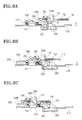
- FIGS. 8A thru 8 C are longitudinal sectional views partially showing the developing unit-toner cartridge assembly of the image forming apparatus in accordance with the present invention.
- a laser printer of the present invention includes a controller portion (not shown) formed in a printer body 1 , an engine portion 4 also formed in the printer body 1 for forming an image under the control of the controller portion, and paper cassettes 2 for feeding paper to the engine portion 4 .
- the engine portion 4 includes a developing unit 100 , a toner cartridge 200 removably disposed on the developing unit 100 for feeding toner, and a fixing unit (not shown) for fixing toner image on the paper.
- the developing unit 100 has a photosensitive drum 101 on which an electrostatic latent image corresponding to a desired image is formed by a laser beam projected from the laser beam scanning unit (LSU) 7 which is charged with electricity by a proper method, such as corona discharge or the like.
- the developing unit 100 of the present invention also includes a charging means for charging the photosensitive drum 101 with a certain amount of electricity, a developing means such as a developing roller for transferring the toner from the developing unit 100 to the photosensitive drum 101 , and a cleaning means for removing residual waste toner from the photosensitive drum 101 .
- the unique feature of the developing unit-toner cartridge assembly in accordance with the preferred embodiment of the present invention is that the toner cartridge is integrally formed with the waste toner recovering device, divided into a fresh toner chamber for holding fresh toner, and a waste toner chamber for holding the waste toner recovered after it is used in the developing unit.
- FIGS. 2 and 3 are traverse sectional views for schematically showing the developing unit-toner cartridge assembly of the image forming apparatus in accordance with the present invention, in which FIG. 2 is a sectional view taken along line I—I of FIG. 1, while FIG. 3 is a sectional view taken along line II—II of FIG. 1 .
- the toner cartridge 200 includes: a cartridge case 210 having a fresh toner chamber 211 holding fresh toner, and a waste toner chamber 212 holding waste toner that is left after being used in the developing unit 100 ; a toner feeding port 231 through which the fresh toner is fed from the fresh toner chamber 211 to the developing unit 100 ; and a toner recovery port 251 through which the waste toner is recovered from the developing unit 100 into the waste toner chamber 212 .
- the developing unit 100 includes a developing unit case 110 having a channel portion 111 formed thereon and connected with the toner cartridge 200 , a toner inlet 131 interconnected with the toner feeding port 231 and serving as the feeding path of the fresh toner, and a toner outlet 151 interconnected with the toner recovery port 251 and serving as the recovery path of the waste toner.
- the toner feeding port 231 is formed on the upper surface of the cartridge case 210
- the toner recovery port 251 is formed on the lower surface of the cartridge case 210
- the toner inlet 131 and the toner outlet 151 are formed on the lower and upper surfaces, respectively, of the channel portion 111 of the developing unit case 110 in such a manner as to interconnect with the toner feeding portion 231 and the toner recovery port 251 , respectively.
- the reference numeral 101 of FIG. 2 indicates a photosensitive drum
- reference numeral 102 indicates a developer agitating chamber.
- the fresh toner in the fresh toner chamber 211 of the cartridge case 210 is fed into the developer agitating chamber 102 of the developing unit 100 through the toner feeding port 231 and the toner inlet 131 .
- the fresh toner is then transferred onto the electric latent image area on the photosensitive drum 101 , and onto the paper. During the transfer, the toner partially remains on the surface of the photosensitive drum 101 .
- Such remaining toner is removed by a blade 103 and is conveyed into the waste recovery chamber 105 by a recovery roller 104 .
- the reference numeral 107 of FIG. 3 refers to a conveyor belt. Accordingly, the waste toner of the waste toner recovery chamber 105 is conveyed toward the toner outlet 151 by the conveyor belt 107 , and is stored in the waste toner chamber 212 of the toner cartridge 200 through the toner recovery port 251 .
- the developing unit 100 has an opening/closing member for selectively opening and closing the toner inlet 131
- the toner cartridge 200 includes a first opening/closing means for selectively opening and closing the toner feeding port 231 , and a second opening/closing means for selectively opening and closing the opening/closing member according to whether the developing unit 100 is mounted or removed.
- FIGS. 4A and 4B are perspective views separately showing the main portion of the present invention, i.e., the developing unit-toner cartridge assembly of the image forming apparatus in accordance with the preferred embodiment of the present invention.
- FIG. 4A shows the area where the toner feeding port 231 of the toner cartridge 200 is formed
- FIG. 4B shows the area where the toner inlet 131 of the developing unit 100 is formed.
- the first opening/closing means includes a toner feeding roller 222 pivotally disposed within the fresh toner chamber 211 of the cartridge case 210 in close contact with the toner feeding port 231 , and a pivotal handle 213 pivotally formed on the outer portion of the cartridge case 210 in connection with a pivotal shaft of the toner feeding roller 222 .
- the toner feeding roller 222 has a rectangular opening 222 a formed therein and corresponding to the toner feeding port 231 to permit the fresh toner from the fresh toner chamber 211 to pass therethrough. Accordingly, by pivoting the pivotal handle 213 , the toner feeding roller 222 is pivoted to selectively interconnect the toner feeding port 231 and the rectangular opening 222 a.
- the second opening/closing means includes a supporting projection 233 protruding outward from the cartridge case 210 , an inserting hole 232 formed in the cartridge case 210 at a predetermined distance from the supporting projection 233 , and a stopper 235 for elastic insertion into locking hole 134 (see FIG. 4B) of developing unit 100 through the inserting hole 232 .
- One end of the stopper 235 is connected to a spring 236 for biasing the stopper 235 toward the locking hole 134 , and a guide segment 235 a protrudes from the side of the stopper 235 .
- the reference numeral 237 refers to a contact surface with an inlet cover 133 (see FIG. 4B) which will be described later.
- the opening/closing member includes the inlet cover 133 sidably disposed on the developing unit case 110 for opening and closing the toner inlet 131 , and the locking hole 134 formed on the upper surface of the inlet cover 133 and corresponding to the inserting hole 232 of the toner cartridge 200 .
- the developing unit case 110 has a guide projection 136 having an inclined surface 136 a and formed at a predetermined distance from the upper portion of the inlet cover 133 .
- the guide projection 136 guides the guide segment 235 a of the stopper 235 during the mounting and removal of the developing unit 100 and the toner cartridge 200 .
- FIGS. 5A thru 5 C are longitudinal sectional views for explaining the opening and closing of the toner inlet 131 during the mounting and removal of the developing unit 100 and the toner cartridge 200 .
- the toner cartridge 200 is pushed into the channel portion 111 of the developing unit 100 . Accordingly, in a state wherein the contact surface 237 of the cartridge case 210 stays in contact with the inlet cover 133 of the developing unit 100 , the toner cartridge 200 is pushed into the printer body 1 ; in other words, the toner cartridge 200 is pushed in a right-hand direction in FIG. 5 A.
- the stopper 235 is pushed into the inserting hole 232 , and the spring 236 is compressed.
- FIG. 5C shows the toner cartridge 200 completely mounted in the printer body 1 .
- the toner feeding port 231 and the toner inlet 131 are interconnected with each other, and the stopper 235 is inserted in the locking hole 134 .
- a user pivots the pivotal handle 213 , and accordingly, the rectangular opening 222 a of the toner feeding roller 222 is interconnected with the toner feeding port 231 .
- the toner cartridge 200 is separated from the developing unit 100 . That is, in the state shown in FIG. 5C, the toner cartridge 200 is pulled out; in other words, the toner cartridge 200 is pulled in a left-hand direction of FIG. 5 C. Accordingly, since the inlet cover 133 is restricted by the stopper 235 inserted in the locking hole 134 , it is moved in relation to the toner cartridge 200 . As shown in FIG. 5B, when the inlet cover 133 keeps moving relation to the toner feeding port 231 , the guide segment 235 a of the stopper 235 is moved along the inclined surface 136 a of the guide projection 136 , and the stopper 235 is accordingly released from the locking hole 134 . Accordingly, the movement of the inlet cover 133 is stopped, and the toner cartridge 200 is exclusively separated from the printer body 1 .
- FIGS. 6A and 6B are perspective views of the developing unit-toner cartridge assembly of the image forming apparatus in accordance with the preferred embodiment of the present invention, in which FIG. 6A shows the area where the toner recovery port 251 of the toner cartridge 200 is formed, and FIG. 6B shows the area where the toner outlet 151 of the developing unit 100 is formed.
- the developing unit 100 includes an outlet cover 152 for selectively opening and closing the toner outlet 151
- the toner cartridge 200 includes a recovery port cover 252 for selectively opening and closing the toner recovery port 251 .
- the outlet cover 152 and the recovery port cover 252 are restricted by a third opening/closing means formed on the toner cartridge 200 and a fourth opening/closing means formed on the developing unit 100 , respectively, and are accordingly opened and closed.
- the recovery port cover 252 is slidably mounted on the cartridge case 210 so as to open and close the toner recovery port 251 .
- the recovery port cover 252 has a hooking projection 252 a formed on its upper surface for being selectively hooked with a third hook (see FIG. 6 B). Further, it is preferable that the recovery port cover 252 have a secondary recovery port 253 which is interconnected with the toner recovery port 251 when the recovery cover 252 is open.
- the third opening/closing means of the toner cartridge 200 includes first and second hooks 254 and 255 , respectively and third and fourth locking rises 257 and 258 , respectively.
- the first hook 254 is pivotally formed on the cartridge case 210 for restricting and releasing one inner end of the recovery port cover 252 while the recovery port cover 252 opens and closes the toner recovery port 251 .
- One end of a pivotal shaft of the first hook 254 is connected with a torsion spring (not shown), which biases the first hook 254 toward the recovery port cover 252 .
- the second hook 255 is formed on the cartridge case 210 in such a manner as to correspond to the first hook 254 and to be pivoted in relation to the first hook 254 .
- a pivotal shaft of the second hook 255 is connected with a first lever 256 .
- the first and the second hooks 254 and 255 are arranged above an extension 254 a of the first hook 254 in such a manner as to overlap an extension 255 a for relative movement.
- the first and the second hooks 254 and 255 respectively, contact first and second locking rises 153 and 154 (described later), respectively, formed on the outlet cover 152 (FIG. 6B) and pivot in relation to the first and the second locking rises 153 and 154 , respectively, during the mounting and removal of the toner cartridge 200 and the developing unit 100 .
- the third and the fourth locking rises 257 and 258 are diagonally opposed relative to each other on opposite sides of the cartridge case 210 contacting the recovery port cover 252 for pivoting a second lever 156 of FIG. 6 B and the fourth hook 158 by contact.
- the outlet cover 152 is slidably connected with the developing unit case 110 for selectively opening and closing the toner outlet 151 .
- the first and second locking rises 153 and 154 respectively, protrude in parallel to the upper surface of the outlet cover 152 at a predetermined distance therebetween.
- the outlet cover 152 also has a hooking groove 152 a formed thereon, through which a fourth hook 158 is hooked.
- the fourth opening/closing means of the developing unit 200 includes the third and fourth hooks 155 and 158 , respectively.
- the third hook 155 is pivotally disposed on the developing unit case 151 , and is hooked in the hooking projection 252 a formed on the upper surface of the recovery port cover 252 , thereby restricting the movement of the recovery port cover 252 .
- the second lever 156 extend toward the recovery port cover 252 and be connected with the pivotal shaft of the third hook 155 when the developing unit 100 is connected with the toner cartridge 200 .
- the second lever 156 is pivoted upward and downward by contact with the third locking rise 257 , thereby pivoting the third hook 155 upward and downward.
- the pivotal shaft of the third hook 155 is connected with a first elastic member 157 for biasing the third hook 155 toward the recovery port cover 252 .
- the fourth hook 158 is elastically pivotable on the developing unit case 110 while being opposed to the third hook 155 across the outlet cover 152 .
- the fourth hook 158 is hooked in the hooking groove 152 a , thereby restricting the movement of the outlet cover 152 .
- a hooking portion 158 a is formed on one end of the fourth hook 158 for being received in the hooking groove 152 a , while a guide portion 158 b protrudes from another end of the fourth hook 158 .
- the guide portion 158 b moves in contact with the fourth locking rise 258 , and accordingly, the fourth hook 158 is pivoted upward and downward.
- a second elastic member 159 be connected to the pivotal shaft 158 c of the fourth hook 158 , and that it bias the fourth hook 158 in such a direction that the hooking portion 158 a is hooked with the hooking groove 152 a.
- FIGS. 7A thru 7 C and 8 A thru 8 C are longitudinal sectional views for explaining the opening and closing of the toner recovery port 251 land the toner outlet 151 during the mounting and removal of the developing unit 100 and the toner cartridge 200 .
- FIGS. 7A thru 7 C are sectional views taken on lines IV—IV of FIG. 6A
- FIGS. 8A thru 8 C are sectional views taken on line IV—IV in the opposite direction. That is, FIGS. 8A thru 8 C are sectional views taken on line V—V of FIG. 6 B.
- the toner cartridge 200 is inserted in the channel portion 111 of the developing unit 100 (see FIG. 3 ). Accordingly, an end of the recovery port cover 252 comes into contact with an end of the outlet cover 152 . At this time, the second hook 255 comes into contact with the second locking rise 154 , and is pivoted in a downward direction in FIG. 7 A. Also, the first hook 254 is moved in relation to the second hook 255 , and is pivoted downward. As a result, the recovery port cover 252 is released from locking status by the first hook 254 . Meanwhile, as shown in FIG. 8A, the outlet cover 152 is restricted by the hooking portion 158 a of the fourth hook 158 inserted in the hooking groove 152 a.
- the outlet cover 152 When the outlet cover 152 is released, the outlet cover 152 is moved in the direction ‘C’ according to the movement of the cartridge case 210 . As a result, as shown in FIGS. 7C and 8C, the toner outlet 151 , secondary recovery port 253 , and toner recovery port 251 are interconnected with each other.
- the toner cartridge 200 is separated from the developing unit 100 in a reverse order. That is, the toner cartridge 200 is pulled out from the printer body 1 in the right-hand direction of FIG. 8C (the reverse of direction ‘C’), and the outlet cover 152 is moved in the right-hand direction in relation to the cartridge case 210 , while the outlet cover 152 is restricted by the second hook 255 . Accordingly, the toner outlet 151 is closed.
- the third hook 155 is hooked in the hooking projection 252 a of the outlet cover 252 , and accordingly, the recovery port cover 252 and the outlet cover 152 are restricted.
- the cartridge case 210 is exclusively moved in the right-hand direction. Accordingly, as shown in FIG. 7A the toner recovery port 251 is closed by the recovery port cover 252 .
- the second lever 156 comes into contact with the third locking rise 257 , pivoting the third hook to a releasing direction relative to the locking state with the hooking projection 252 a .
- the toner cartridge 200 is completely removed from the developing unit 100 .
- the toner feeding path and the toner recovery path are opened and closed by the relative movement of the developing unit 100 and the toner cartridge 200 . Accordingly, the user has convenience in handling, since he/she does not have to perform additional steps to open and close the toner feeding path and the toner recovery path.
- the toner feeding path and the toner recovery path are opened only when the developing unit 100 and the toner cartridge 200 are properly assembled with each other, print quality deterioration under inefficient toner supply and recovery, as well as interior contamination of the printer body 1 by the toner leakage, can be prevented.
Landscapes
- Physics & Mathematics (AREA)
- General Physics & Mathematics (AREA)
- Engineering & Computer Science (AREA)
- Computer Vision & Pattern Recognition (AREA)
- Dry Development In Electrophotography (AREA)
- Electrophotography Configuration And Component (AREA)
Abstract
Description
Claims (8)
Applications Claiming Priority (3)
| Application Number | Priority Date | Filing Date | Title |
|---|---|---|---|
| KR1020000086390A KR100362390B1 (en) | 2000-12-29 | 2000-12-29 | Developing device-toner cartridge assembly for image forming apparatus |
| KR86390/2000 | 2000-12-29 | ||
| KR2000-86390 | 2000-12-29 |
Publications (2)
| Publication Number | Publication Date |
|---|---|
| US20020085857A1 US20020085857A1 (en) | 2002-07-04 |
| US6526243B2 true US6526243B2 (en) | 2003-02-25 |
Family
ID=19704016
Family Applications (1)
| Application Number | Title | Priority Date | Filing Date |
|---|---|---|---|
| US09/964,376 Expired - Fee Related US6526243B2 (en) | 2000-12-29 | 2001-09-28 | Developing unit-toner cartridge assembly of image forming apparatus |
Country Status (3)
| Country | Link |
|---|---|
| US (1) | US6526243B2 (en) |
| JP (1) | JP3418618B2 (en) |
| KR (1) | KR100362390B1 (en) |
Cited By (14)
| Publication number | Priority date | Publication date | Assignee | Title |
|---|---|---|---|---|
| US6728500B2 (en) * | 2001-08-23 | 2004-04-27 | Panasonic Communications Co., Ltd. | Process cartridge attachable to recording apparatus and recording apparatus |
| US20060062601A1 (en) * | 2004-09-23 | 2006-03-23 | Samsung Electronics Co., Ltd. | Developer cartridge and liquid-type image forming apparatus |
| US20060104663A1 (en) * | 2004-11-12 | 2006-05-18 | Canon Kabushiki Kaisha | Cartridge for image forming apparatus |
| US20070065196A1 (en) * | 2005-09-22 | 2007-03-22 | Lexmark International, Inc. | Device for moving toner within an image forming device |
| US20070122205A1 (en) * | 2005-01-26 | 2007-05-31 | Nobuyuki Taguchi | Toner container and image forming apparatus |
| US20070147902A1 (en) * | 2005-04-27 | 2007-06-28 | Nobuyuki Taguchi | Toner container and image forming apparatus |
| US20070269237A1 (en) * | 2006-05-18 | 2007-11-22 | Kabushiki Kaisha Toshiba | Toner cartridge |
| US20080038019A1 (en) * | 2002-05-20 | 2008-02-14 | Nobuo Kasahara | Developing device using a two-ingredient type developer and image forming apparatus including the same |
| US20080187331A1 (en) * | 2003-02-28 | 2008-08-07 | Kabushiki Kaisha Toshiba | Toner cartridge and developing device |
| US20080286013A1 (en) * | 2003-02-28 | 2008-11-20 | Hiroshi Hosokawa | Developer container, developer supplying device, and image forming apparatus |
| US20100189470A1 (en) * | 2006-11-09 | 2010-07-29 | Hideo Yoshizawa | Toner container and image forming apparatus |
| US7778577B2 (en) | 2001-10-30 | 2010-08-17 | Ricoh Company, Ltd. | Developer container for an image forming apparatus |
| US7890022B2 (en) | 2008-02-22 | 2011-02-15 | Samsung Electronics Co., Ltd. | Cover member, developing cartridge and developing unit for image forming apparatus |
| US20110103856A1 (en) * | 2009-10-29 | 2011-05-05 | Fuji Xerox Co., Ltd. | Powder recovery container and image forming apparatus |
Families Citing this family (38)
| Publication number | Priority date | Publication date | Assignee | Title |
|---|---|---|---|---|
| ES2377847T3 (en) | 1999-01-13 | 2012-04-02 | Bayer Healthcare Llc | Diphenyl ureas substituted with omega-carboxy aryl as kinase inhibitors p38 |
| US8124630B2 (en) | 1999-01-13 | 2012-02-28 | Bayer Healthcare Llc | ω-carboxyaryl substituted diphenyl ureas as raf kinase inhibitors |
| JP4659231B2 (en) * | 2001-02-21 | 2011-03-30 | 東芝テック株式会社 | Image forming apparatus, process unit, and toner cartridge |
| JP4562941B2 (en) * | 2001-04-16 | 2010-10-13 | 株式会社リコー | Image forming apparatus |
| CN1318404C (en) | 2002-02-11 | 2007-05-30 | 拜耳制药公司 | Aryl ureas as kinase inhibitors |
| DK1478358T3 (en) | 2002-02-11 | 2013-10-07 | Bayer Healthcare Llc | Sorafenibtosylate for the treatment of diseases characterized by abnormal angiogenesis |
| WO2003068229A1 (en) | 2002-02-11 | 2003-08-21 | Bayer Pharmaceuticals Corporation | Pyridine, quinoline, and isoquinoline n-oxides as kinase inhibitors |
| JP4694100B2 (en) * | 2003-02-28 | 2011-06-01 | 株式会社東芝 | Toner cartridge and developing device |
| UY28213A1 (en) | 2003-02-28 | 2004-09-30 | Bayer Pharmaceuticals Corp | NEW CYANOPIRIDINE DERIVATIVES USEFUL IN THE TREATMENT OF CANCER AND OTHER DISORDERS. |
| WO2004113274A2 (en) | 2003-05-20 | 2004-12-29 | Bayer Pharmaceuticals Corporation | Diaryl ureas with kinase inhibiting activity |
| EA010485B1 (en) | 2003-07-23 | 2008-10-30 | Байер Фамэсьютиклс Копэрейшн | N,n-diphenyl urea derivative, pharmaceutical composition (embodiments) thereof, and method for the treatment and prevention of diseases and conditions using it (embodiments) |
| US7406272B2 (en) * | 2004-07-12 | 2008-07-29 | Seiko Epson Corporation | Image forming apparatus and system with attachable and detachable developer container |
| US7330681B2 (en) * | 2004-08-30 | 2008-02-12 | Seiko Epson Corporation | Developing device, image forming apparatus, and image forming system |
| JP4645116B2 (en) * | 2004-09-22 | 2011-03-09 | 富士ゼロックス株式会社 | Process cartridge and image forming apparatus having the same |
| KR100683184B1 (en) * | 2005-06-24 | 2007-02-15 | 삼성전자주식회사 | Process cartridge for image forming apparatus |
| JP2007086392A (en) * | 2005-09-22 | 2007-04-05 | Fuji Xerox Co Ltd | Image forming apparatus |
| DE102006007304B3 (en) * | 2006-02-16 | 2007-09-13 | OCé PRINTING SYSTEMS GMBH | Arrangement for conveying toner from a toner reservoir into a toner receiving container, in particular in a printing or copying device |
| EP1821157A3 (en) * | 2006-02-20 | 2013-08-21 | Konica Minolta Business Technologies, Inc. | Toner cartridge, process cartridge, imaging cartridge, and image forming apparatus to which thoses cartridges are attachable |
| JP4378374B2 (en) * | 2006-03-10 | 2009-12-02 | キヤノン株式会社 | Process cartridge, developer supply cartridge, and electrophotographic image forming apparatus |
| JP4802845B2 (en) * | 2006-04-25 | 2011-10-26 | 村田機械株式会社 | Image forming apparatus |
| JP2007310146A (en) * | 2006-05-18 | 2007-11-29 | Toshiba Corp | Toner cartridge |
| US7548710B2 (en) * | 2006-10-25 | 2009-06-16 | Lexmark International, Inc. | Dual sliding shutter system |
| US8208846B2 (en) * | 2007-02-28 | 2012-06-26 | Kyocera Mita Corporation | Image forming apparatus having a locking mechanism for preventing a conveyance unit from being pulled out from the image forming apparatus |
| KR100892110B1 (en) * | 2008-02-22 | 2009-04-08 | 삼성전자주식회사 | Developing cartridge, image forming apparatus having the same, and printing method for an image forming apparatus |
| KR100899350B1 (en) * | 2008-02-22 | 2009-05-27 | 삼성전자주식회사 | Developing apparatus, image forming apparatus having the same, and toner suppling method for a developing apparatus |
| KR100912900B1 (en) * | 2008-02-22 | 2009-08-20 | 삼성전자주식회사 | Developer cartrage, developing device and image forming apparatus having the same |
| KR100933290B1 (en) * | 2008-02-22 | 2009-12-22 | 삼성전자주식회사 | A memory unit, a developer cartridge, a developing apparatus and an image forming apparatus including the same |
| KR100915396B1 (en) * | 2008-02-22 | 2009-09-03 | 삼성전자주식회사 | Toner cartridge, a devloping unit and image forming apparatus having the same |
| US8918030B2 (en) * | 2008-11-27 | 2014-12-23 | Ricoh Company, Limited | Powder supplying device and image forming apparatus |
| JP5523146B2 (en) * | 2010-03-01 | 2014-06-18 | キヤノン株式会社 | Image forming apparatus |
| JP5874231B2 (en) | 2011-07-29 | 2016-03-02 | ブラザー工業株式会社 | Image forming apparatus |
| JP5768567B2 (en) | 2011-07-29 | 2015-08-26 | ブラザー工業株式会社 | Image forming apparatus |
| JP5514792B2 (en) * | 2011-11-25 | 2014-06-04 | 京セラドキュメントソリューションズ株式会社 | Developing mechanism and image forming apparatus |
| JP6447271B2 (en) * | 2015-03-13 | 2019-01-09 | 富士ゼロックス株式会社 | Developing device and image forming apparatus |
| JP6380324B2 (en) * | 2015-10-02 | 2018-08-29 | 京セラドキュメントソリューションズ株式会社 | Toner container and image forming apparatus |
| JP2019082642A (en) * | 2017-10-31 | 2019-05-30 | エイチピー プリンティング コリア カンパニー リミテッド | Development system |
| KR20200052715A (en) * | 2018-11-07 | 2020-05-15 | 휴렛-팩커드 디벨롭먼트 컴퍼니, 엘.피. | Shutter for effectively opening and closing waste toner collector of image forming device |
| JP2022131237A (en) * | 2021-02-26 | 2022-09-07 | キヤノン株式会社 | Image forming apparatus |
Citations (5)
| Publication number | Priority date | Publication date | Assignee | Title |
|---|---|---|---|---|
| JPH0635321A (en) * | 1992-07-17 | 1994-02-10 | Ricoh Co Ltd | Electrophotographic recorder |
| US5506665A (en) * | 1994-05-12 | 1996-04-09 | Brother Kogyo Kabushiki Kaisha | Developing device having detachable toner box for use in image recording apparatus |
| US5614996A (en) * | 1994-03-03 | 1997-03-25 | Kyocera Corporation | Toner storage unit, residual toner collect unit, toner container with these units and image forming apparatus with such toner container |
| US6041212A (en) * | 1997-11-06 | 2000-03-21 | Mita Industrial Co., Ltd. | Toner replenishing device of image forming machine and toner cartridge for use therein |
| US6289194B1 (en) * | 1999-10-15 | 2001-09-11 | Matsushita Graphic Communication Systems, Inc. | Toner cartridge and image forming apparatus |
-
2000
- 2000-12-29 KR KR1020000086390A patent/KR100362390B1/en not_active IP Right Cessation
-
2001
- 2001-09-28 US US09/964,376 patent/US6526243B2/en not_active Expired - Fee Related
- 2001-10-31 JP JP2001335107A patent/JP3418618B2/en not_active Expired - Fee Related
Patent Citations (5)
| Publication number | Priority date | Publication date | Assignee | Title |
|---|---|---|---|---|
| JPH0635321A (en) * | 1992-07-17 | 1994-02-10 | Ricoh Co Ltd | Electrophotographic recorder |
| US5614996A (en) * | 1994-03-03 | 1997-03-25 | Kyocera Corporation | Toner storage unit, residual toner collect unit, toner container with these units and image forming apparatus with such toner container |
| US5506665A (en) * | 1994-05-12 | 1996-04-09 | Brother Kogyo Kabushiki Kaisha | Developing device having detachable toner box for use in image recording apparatus |
| US6041212A (en) * | 1997-11-06 | 2000-03-21 | Mita Industrial Co., Ltd. | Toner replenishing device of image forming machine and toner cartridge for use therein |
| US6289194B1 (en) * | 1999-10-15 | 2001-09-11 | Matsushita Graphic Communication Systems, Inc. | Toner cartridge and image forming apparatus |
Cited By (52)
| Publication number | Priority date | Publication date | Assignee | Title |
|---|---|---|---|---|
| US6728500B2 (en) * | 2001-08-23 | 2004-04-27 | Panasonic Communications Co., Ltd. | Process cartridge attachable to recording apparatus and recording apparatus |
| US7778577B2 (en) | 2001-10-30 | 2010-08-17 | Ricoh Company, Ltd. | Developer container for an image forming apparatus |
| US7894753B2 (en) | 2002-05-20 | 2011-02-22 | Ricoh Company, Ltd. | Developer container including mouth member and image forming apparatus including the same |
| US20080038019A1 (en) * | 2002-05-20 | 2008-02-14 | Nobuo Kasahara | Developing device using a two-ingredient type developer and image forming apparatus including the same |
| US8195070B2 (en) | 2003-02-28 | 2012-06-05 | Ricoh Company, Ltd. | Developer container, developer supplying device, and image forming apparatus |
| US7676178B2 (en) | 2003-02-28 | 2010-03-09 | Kabushiki Kaisha Toshiba | Toner cartridge having grip, exchangeably inserted into revolver and replenishing toner into developing device |
| US20110026973A1 (en) * | 2003-02-28 | 2011-02-03 | Hiroshi Hosokawa | Developer container, developer supplying device, and image forming apparatus |
| US20080286013A1 (en) * | 2003-02-28 | 2008-11-20 | Hiroshi Hosokawa | Developer container, developer supplying device, and image forming apparatus |
| US8005406B2 (en) | 2003-02-28 | 2011-08-23 | Ricoh Company, Ltd. | Developer container, developer supplying device, and image forming apparatus |
| US20080187331A1 (en) * | 2003-02-28 | 2008-08-07 | Kabushiki Kaisha Toshiba | Toner cartridge and developing device |
| US7835673B2 (en) | 2003-02-28 | 2010-11-16 | Ricoh Company, Ltd. | Developer container, developer supplying device, and image forming apparatus |
| US7305205B2 (en) * | 2004-09-23 | 2007-12-04 | Samsung Electronics Co., Ltd. | Developer cartridge having a movable cover and liquid-type image forming apparatus |
| US20060062601A1 (en) * | 2004-09-23 | 2006-03-23 | Samsung Electronics Co., Ltd. | Developer cartridge and liquid-type image forming apparatus |
| CN100465811C (en) * | 2004-09-23 | 2009-03-04 | 三星电子株式会社 | Developer cartridge and liquid-type image forming apparatus |
| US7486910B2 (en) | 2004-11-12 | 2009-02-03 | Canon Kabushiki Kaisha | Cartridge detachably mounted to an image forming apparatus including a lock member engagable with a wall of the image forming apparatus |
| US20060104663A1 (en) * | 2004-11-12 | 2006-05-18 | Canon Kabushiki Kaisha | Cartridge for image forming apparatus |
| US20070160393A1 (en) * | 2005-01-26 | 2007-07-12 | Nobuyuki Taguchi | Toner container and image forming apparatus |
| US20070122205A1 (en) * | 2005-01-26 | 2007-05-31 | Nobuyuki Taguchi | Toner container and image forming apparatus |
| US8126375B2 (en) | 2005-04-27 | 2012-02-28 | Ricoh Co., Ltd. | Toner container and image forming apparatus |
| US20070147902A1 (en) * | 2005-04-27 | 2007-06-28 | Nobuyuki Taguchi | Toner container and image forming apparatus |
| US7991334B2 (en) | 2005-04-27 | 2011-08-02 | Ricoh Co., Ltd. | Toner container and image forming apparatus |
| US20110002713A1 (en) * | 2005-04-27 | 2011-01-06 | Nobuyuki Taguchi | Toner container and image forming apparatus |
| US20070154244A1 (en) * | 2005-04-27 | 2007-07-05 | Nobuyuki Taguchi | Toner container and image forming apparatus |
| US7702262B2 (en) | 2005-04-27 | 2010-04-20 | Ricoh Co., Ltd. | Toner container including a container body with a gripper at the end thereof, and associated method |
| US7706699B2 (en) | 2005-04-27 | 2010-04-27 | Ricoh Co., Ltd. | Toner container and image forming apparatus |
| US20070160394A1 (en) * | 2005-04-27 | 2007-07-12 | Nobuyuki Taguchi | Toner container and image forming apparatus |
| US7853184B2 (en) | 2005-04-27 | 2010-12-14 | Ricoh Co., Ltd. | Toner container and image forming apparatus |
| US20070177886A1 (en) * | 2005-04-27 | 2007-08-02 | Nobuyuki Taguchi | Toner container and image forming apparatus |
| US7822371B2 (en) | 2005-04-27 | 2010-10-26 | Ricoh Co., Ltd. | Toner container and image forming apparatus |
| US7720417B2 (en) | 2005-06-07 | 2010-05-18 | Ricoh Co., Ltd. | Toner container and image forming apparatus |
| US20070147900A1 (en) * | 2005-06-07 | 2007-06-28 | Nobuyuki Taguchi | Toner container and image forming apparatus |
| US7835675B2 (en) * | 2005-06-07 | 2010-11-16 | Ricoh Co., Ltd. | Toner container and image forming apparatus |
| US7853183B2 (en) * | 2005-06-07 | 2010-12-14 | Ricoh Co., Ltd. | Toner container and image forming apparatus |
| USRE47086E1 (en) | 2005-06-07 | 2018-10-16 | Ricoh Company, Ltd. | Toner container and image forming apparatus |
| TWI464545B (en) * | 2005-06-07 | 2014-12-11 | Ricoh Co Ltd | Toner containers |
| US20110008075A1 (en) * | 2005-06-07 | 2011-01-13 | Nobuyuki Taguchi | Toner container and image forming apparatus |
| US8160461B2 (en) | 2005-06-07 | 2012-04-17 | Ricoh Co., Ltd. | Toner container and image forming apparatus |
| US7826777B2 (en) | 2005-06-07 | 2010-11-02 | Ricoh Co., Ltd. | Toner container and image forming apparatus having first and second biasing elements that bias the toner container |
| US20070154243A1 (en) * | 2005-06-07 | 2007-07-05 | Nobuyuki Taguchi | Toner container and image forming apparatus |
| US7257363B2 (en) * | 2005-09-22 | 2007-08-14 | Lexmark International, Inc. | Device for moving toner within an image forming device |
| US20070065196A1 (en) * | 2005-09-22 | 2007-03-22 | Lexmark International, Inc. | Device for moving toner within an image forming device |
| US7574163B2 (en) | 2006-05-18 | 2009-08-11 | Kabushiki Kaisha Toshiba | Toner cartridge |
| US20070269237A1 (en) * | 2006-05-18 | 2007-11-22 | Kabushiki Kaisha Toshiba | Toner cartridge |
| US20090290910A1 (en) * | 2006-05-18 | 2009-11-26 | Kabushiki Kaisha Toshiba | Toner cartridge |
| US8064805B2 (en) | 2006-05-18 | 2011-11-22 | Kabushiki Kaisha Toshiba | Toner cartridge |
| US8244163B2 (en) | 2006-11-09 | 2012-08-14 | Ricoh Company, Limited | Toner container and image forming apparatus |
| US8050597B2 (en) | 2006-11-09 | 2011-11-01 | Ricoh Company, Limited | Toner container having a gear portion and image forming apparatus |
| US20100189470A1 (en) * | 2006-11-09 | 2010-07-29 | Hideo Yoshizawa | Toner container and image forming apparatus |
| US7890022B2 (en) | 2008-02-22 | 2011-02-15 | Samsung Electronics Co., Ltd. | Cover member, developing cartridge and developing unit for image forming apparatus |
| CN101515137B (en) * | 2008-02-22 | 2011-11-16 | 三星电子株式会社 | Cover member, developing cartridge and developing unit |
| US20110103856A1 (en) * | 2009-10-29 | 2011-05-05 | Fuji Xerox Co., Ltd. | Powder recovery container and image forming apparatus |
| US8290421B2 (en) | 2009-10-29 | 2012-10-16 | Fuji Xerox Co., Ltd. | Powder recovery container and image forming apparatus |
Also Published As
| Publication number | Publication date |
|---|---|
| JP3418618B2 (en) | 2003-06-23 |
| KR20020058323A (en) | 2002-07-12 |
| KR100362390B1 (en) | 2002-11-23 |
| JP2002214898A (en) | 2002-07-31 |
| US20020085857A1 (en) | 2002-07-04 |
Similar Documents
| Publication | Publication Date | Title |
|---|---|---|
| US6526243B2 (en) | Developing unit-toner cartridge assembly of image forming apparatus | |
| US5337134A (en) | Sheet inverting unit and an imaging forming apparatus employing the same | |
| US7515854B2 (en) | Image forming apparatus | |
| US7555235B2 (en) | Image forming apparatus enabling user to directly clean discharge wire | |
| US8320798B2 (en) | Sheet conveying device and image forming apparatus | |
| US8203586B2 (en) | Image forming apparatus having a cleaning member configured to clean a transparent member of an optical device | |
| US20080013988A1 (en) | Developer supply container | |
| JP4552535B2 (en) | Electrophotographic printing machine | |
| JP2006323082A (en) | Developer supply container | |
| US9268259B2 (en) | Developer material holding apparatus, supporting apparatus that supports the developer material holding apparatus, and image forming apparatus | |
| US20040247331A1 (en) | Developer supply container | |
| JP3757736B2 (en) | Process cartridge and image forming apparatus using the same | |
| EP1361482B1 (en) | Image forming apparatus with an intermediate transfer belt | |
| US7031638B2 (en) | Color image forming apparatus with a removable and inclined intermediate transfer body unit | |
| US20050260015A1 (en) | Image forming device | |
| JPH06222628A (en) | Image forming device | |
| US6934492B2 (en) | Toner supply container, image formation unit and image forming apparatus | |
| JP4967648B2 (en) | Image forming apparatus | |
| JP6544999B2 (en) | Storage container and image forming apparatus | |
| JP4553571B2 (en) | Image forming apparatus | |
| JP2009271276A (en) | Waste toner recovering device and image forming apparatus using the same | |
| JP3714161B2 (en) | Image forming apparatus | |
| JP4360367B2 (en) | Image forming apparatus using process cartridge | |
| JPH1195638A (en) | Image forming unit | |
| JPH0836349A (en) | Image forming device |
Legal Events
| Date | Code | Title | Description |
|---|---|---|---|
| AS | Assignment |
Owner name: SAMSUNG ELECTRONICS CO., LTD., KOREA, REPUBLIC OF Free format text: ASSIGNMENT OF ASSIGNORS INTEREST;ASSIGNORS:KIM, KYUNG-KWAN;PAK, KI-JU;REEL/FRAME:012223/0712 Effective date: 20010925 |
|
| FEPP | Fee payment procedure |
Free format text: PAYOR NUMBER ASSIGNED (ORIGINAL EVENT CODE: ASPN); ENTITY STATUS OF PATENT OWNER: LARGE ENTITY |
|
| FPAY | Fee payment |
Year of fee payment: 4 |
|
| FPAY | Fee payment |
Year of fee payment: 8 |
|
| FEPP | Fee payment procedure |
Free format text: PAYOR NUMBER ASSIGNED (ORIGINAL EVENT CODE: ASPN); ENTITY STATUS OF PATENT OWNER: LARGE ENTITY Free format text: PAYER NUMBER DE-ASSIGNED (ORIGINAL EVENT CODE: RMPN); ENTITY STATUS OF PATENT OWNER: LARGE ENTITY |
|
| REMI | Maintenance fee reminder mailed | ||
| LAPS | Lapse for failure to pay maintenance fees | ||
| STCH | Information on status: patent discontinuation |
Free format text: PATENT EXPIRED DUE TO NONPAYMENT OF MAINTENANCE FEES UNDER 37 CFR 1.362 |
|
| FP | Lapsed due to failure to pay maintenance fee |
Effective date: 20150225 |
|
| AS | Assignment |
Owner name: S-PRINTING SOLUTION CO., LTD., KOREA, REPUBLIC OF Free format text: ASSIGNMENT OF ASSIGNORS INTEREST;ASSIGNOR:SAMSUNG ELECTRONICS CO., LTD;REEL/FRAME:041852/0125 Effective date: 20161104 |