US6471065B1 - Multistack pizza bag - Google Patents
Multistack pizza bag Download PDFInfo
- Publication number
- US6471065B1 US6471065B1 US09/708,320 US70832000A US6471065B1 US 6471065 B1 US6471065 B1 US 6471065B1 US 70832000 A US70832000 A US 70832000A US 6471065 B1 US6471065 B1 US 6471065B1
- Authority
- US
- United States
- Prior art keywords
- wall
- bag
- side wall
- attached
- insulated
- Prior art date
- Legal status (The legal status is an assumption and is not a legal conclusion. Google has not performed a legal analysis and makes no representation as to the accuracy of the status listed.)
- Expired - Fee Related, expires
Links
Images


Classifications
-
- A—HUMAN NECESSITIES
- A47—FURNITURE; DOMESTIC ARTICLES OR APPLIANCES; COFFEE MILLS; SPICE MILLS; SUCTION CLEANERS IN GENERAL
- A47J—KITCHEN EQUIPMENT; COFFEE MILLS; SPICE MILLS; APPARATUS FOR MAKING BEVERAGES
- A47J47/00—Kitchen containers, stands or the like, not provided for in other groups of this subclass; Cutting-boards, e.g. for bread
- A47J47/14—Carriers for prepared human food
- A47J47/145—Hand carriers for pizza delivery, e.g. with thermal insulation, heating means or humidity control
-
- A—HUMAN NECESSITIES
- A45—HAND OR TRAVELLING ARTICLES
- A45C—PURSES; LUGGAGE; HAND CARRIED BAGS
- A45C7/00—Collapsible or extensible purses, luggage, bags or the like
- A45C7/0059—Flexible luggage; Hand bags
- A45C7/0077—Flexible luggage; Hand bags collapsible to a minimal configuration, e.g. for storage purposes
-
- B—PERFORMING OPERATIONS; TRANSPORTING
- B65—CONVEYING; PACKING; STORING; HANDLING THIN OR FILAMENTARY MATERIAL
- B65D—CONTAINERS FOR STORAGE OR TRANSPORT OF ARTICLES OR MATERIALS, e.g. BAGS, BARRELS, BOTTLES, BOXES, CANS, CARTONS, CRATES, DRUMS, JARS, TANKS, HOPPERS, FORWARDING CONTAINERS; ACCESSORIES, CLOSURES, OR FITTINGS THEREFOR; PACKAGING ELEMENTS; PACKAGES
- B65D81/00—Containers, packaging elements, or packages, for contents presenting particular transport or storage problems, or adapted to be used for non-packaging purposes after removal of contents
- B65D81/38—Containers, packaging elements, or packages, for contents presenting particular transport or storage problems, or adapted to be used for non-packaging purposes after removal of contents with thermal insulation
- B65D81/3888—Containers, packaging elements, or packages, for contents presenting particular transport or storage problems, or adapted to be used for non-packaging purposes after removal of contents with thermal insulation wrappers or flexible containers, e.g. pouches, bags
-
- A—HUMAN NECESSITIES
- A45—HAND OR TRAVELLING ARTICLES
- A45C—PURSES; LUGGAGE; HAND CARRIED BAGS
- A45C13/00—Details; Accessories
- A45C13/36—Reinforcements for edges, corners, or other parts
-
- B—PERFORMING OPERATIONS; TRANSPORTING
- B65—CONVEYING; PACKING; STORING; HANDLING THIN OR FILAMENTARY MATERIAL
- B65D—CONTAINERS FOR STORAGE OR TRANSPORT OF ARTICLES OR MATERIALS, e.g. BAGS, BARRELS, BOTTLES, BOXES, CANS, CARTONS, CRATES, DRUMS, JARS, TANKS, HOPPERS, FORWARDING CONTAINERS; ACCESSORIES, CLOSURES, OR FITTINGS THEREFOR; PACKAGING ELEMENTS; PACKAGES
- B65D2585/00—Containers, packaging elements or packages specially adapted for particular articles or materials
- B65D2585/30—Containers, packaging elements or packages specially adapted for particular articles or materials for articles particularly sensitive to damage by shock or pressure
- B65D2585/36—Containers, packaging elements or packages specially adapted for particular articles or materials for articles particularly sensitive to damage by shock or pressure for biscuits or other bakery products
- B65D2585/363—Containers, packaging elements or packages specially adapted for particular articles or materials for articles particularly sensitive to damage by shock or pressure for biscuits or other bakery products specific products
- B65D2585/366—Pizza
Definitions
- the present invention is directed toward insulated multistack pizza carriers.
- the pizza carriers of the present invention comprise a top wall, a bottom wall, a back wall, a front wall and side walls.
- Insulated bags have been used to carry pizzas. Such bags lack the internal volume and the structural integrity needed to carry more than a relatively small number of pizzas.
- Prior art pizza bags have limited insulating capacity which limits the duration that pizza can be carried in such prior art bags without cooling to near ambient temperature conditions.
- the present invention is directed toward a thermally insulated multistack pizza bag comprising an insulated back wall comprising a top outer edge, a bottom outer edge, a first side outer edge, and a second side outer edge.
- the pizza bag further comprises an insulated top wall comprising a back edge attached to the top outer edge of the back wall such that the top wall is substantially perpendicular to the back wall and further comprising a front edge opposite the back edge.
- the invention further comprises a handle.
- the handle is attached to the top wall and an adhesive strip is mounted on the top wall within 18 inches of the front edge.
- the handle is attached to the bottom of the pizza bag.
- the pizza bag also further comprises an insulated bottom wall comprising a back edge attached to the bottom outer edge of the back wall such that the bottom wall is substantially perpendicular to the back wall and further comprising a front edge opposite the bottom wall back edge.
- the bottom wall further comprises a horizontally extending rib channel.
- the invention further comprises a first insulated side wall attached to the back wall, bottom wall and top wall such that the first side wall, is substantially perpendicular to the back wall, the bottom wall, and the top wall, when the first side wall is in an unfolded position.
- the first side wall comprises an upper section comprising a vertically extending rib channel a lower section comprising a vertically extending rib channel and a horizontally extending joint at the intersection of the upper and lower sections.
- the invention also comprises a second insulated side wall attached to the back wall, bottom wall, and top wall, such that the second side wall is substantially perpendicular to the back wall, the bottom wall, and the top wall, when the second side wall is in an unfolded position.
- the second side wall comprises an upper section comprising a vertically extending rib channel, a lower section comprising a vertically extending rib channel, and a horizontally extending joint at the intersection of the upper section and lower section.
- the second side wall is attached to the top wall and bottom walls opposite from the first side wall.
- the second side wall further comprises a front section.
- the invention further comprises a rib placed in each rib channel.
- the invention further comprises an insulated front wall comprising a bottom border, a top border, and two side borders.
- the bottom border is pivotably attached to the front edge of the bottom wall.
- the invention further comprises a closure flap attached to the top border of the front wall, and sized sufficiently large to extend over the adhesive strip.
- the invention also comprises an adhesive affixed to the closure flap such that when the closure flap is placed on the adhesive strip, the adhesive material adheres to the adhesive strip.
- FIG. 1 is an isometric view of the present invention in an unfolded position.
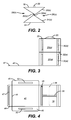
- FIG. 2 is a front view of the present invention in a partially folded position.
- FIG. 3 is a side view of an embodiment of the second side wall.
- FIG. 4 is a top view of an embodiment of the front wall.
- the present invention is directed toward a thermally insulated multistack pizza bag comprising an insulated back wall 10 comprising a top outer edge 11 , a bottom outer edge 12 , a first side outer edge 13 , and a second side outer edge 14 as shown in FIG. 1 .
- the pizza bag further comprises an insulated top wall 16 comprising a back edge 17 attached to the top outer edge of the back wall such that the top wall is substantially perpendicular to the back wall and further comprising a front edge 18 opposite the back edge as shown in FIG. 1 .
- the top wall comprises a horizontally extending rib channel 48 as shown in FIGS. 1 and 4.
- the top wall and the bottom wall are rectangular.
- the invention further comprises a handle 20 attached to the top wall and an adhesive strip 23 mounted on the top wall within 18 inches of the front edge as shown in FIGS. 1 and 3.
- the invention further comprises an insulated bottom wall 24 comprising a back edge 25 attached to the bottom outer edge of the back wall such that the bottom wall is substantially perpendicular to the back wall and further comprising a front edge 26 opposite the bottom wall back edge.
- the bottom wall further comprises a horizontally extending rib channel 27 as shown in FIG. 1 .
- the top and the bottom wall comprise two substantially parallel rib channels as shown in FIG. 1 .
- the invention further comprises a first insulated side wall 28 ( a ) attached to the back wall, bottom wall and top wall such that the first side wall, is substantially perpendicular to the back wall, the bottom wall, and the top wall, when the first side wall is in an unfolded position as shown in FIGS. 1 and 3.
- the first side wall comprises an upper section 29 ( a ) comprising a vertically extending rib channel 30 ( a ) a lower section 31 ( a ) comprising a vertically extending rib channel 30 ( a ) and a horizontally extending joint 32 ( a ) at the intersection of the upper and lower sections as shown in FIGS. 1 and 3.
- the first side wall further comprises a front section 33 ( a ) as shown in FIG. 1 .
- the invention further comprises a second insulated side wall 28 ( b ) attached to the back wall, bottom wall, and top wall, such that the second side wall is substantially perpendicular to the back wall, the bottom wall, and the top wall, when the second side wall is in an unfolded position as shown in FIG. 1 .
- the second side wall comprises an upper section 29 ( b ) comprising a vertically extending rib channel, 30 ( b ) a lower section 31 ( b ) comprising a vertically extending rib channel, and a horizontally extending joint 32 ( b ) at the intersection of the upper section and lower section.
- the second side wall is attached to the top wall and bottom walls opposite from the first side wall as shown in FIG. 1 .
- the second side wall further comprises a front section 33 ( b ) as shown in FIG. 1 .
- the side walls may be folded inwardly as shown in FIG. 2 .
- the joint comprises stitches.
- the upper section and lower section of each side wall comprise two substantially parallel rib channels.
- first side wall and second side wall are rectangular.
- height of the side walls in an unfolded position is at least 1.0 inch.
- the invention further comprises a rib 39 placed in each rib channel as shown in FIG. 1 .
- the ribs are flexible.
- the ribs are inflexible.
- each of the ribs is positioned such that the ribs in the upper section of the first and second side walls are spaced apart from the ribs in the lower sections of the first and second side walls, respectively.
- the spacing between the upper section ribs and the lower section ribs is centrally located on each side wall, as shown in FIG. 3 .
- the central location of the spacing between the upper and lower ribs permits the side walls to be folded inward along the location of the rib spacing, as shown in FIG. 2 .
- FIG. 1 the ribs are flexible.
- the ribs are inflexible.
- each of the ribs is positioned such that the ribs in the upper section of the first and second side walls are spaced apart from the ribs in the lower sections of the first and second side walls, respectively.
- each side wall comprises one pair of parallel rib channels in the upper portion and one pair of parallel rib channels in the lower portion.
- each rib channel in each side wall upper portion is vertically aligned with a rib channel in the lower portion of the side wall.
- the invention further comprises an insulated front wall 42 comprising a bottom border 43 , a top border, 44 , and two side borders 50 as shown in FIGS. 1 and 4.
- the bottom border is pivotably attached to the front edge of the bottom wall.
- the invention further comprises a closure flap 46 attached to the top border of the front wall, and sized sufficiently large to extend over the adhesive strip.
- the invention also comprises an adhesive 47 affixed to the closure flap such that when the closure flap is placed on the adhesive strip, the adhesive material adheres to the adhesive strip as shown in FIGS. 1 and 4.
- the adhesive strip and the adhesive material comprise hook and loop fastening members.
- the invention further comprises a side closure flap 45 attached to each border on the front wall, a side adhesive strip 51 extending vertically on the front section of each side wall and adhesive material 52 mounted on each of said side closure flaps such that when each said closure flap is placed on said adhesive strip, said adhesive material adheres to said adhesive strip as shown in FIGS. 1 and 4.
- the side walls, top wall, bottom wall, and front wall define an internal volume of at least 4.0 cubic inches when the side walls are in an unfolded position.
- the internal volume of the pizza bag is at least 2.0 cubic feet when the side walls are in an unfolded position.
- the bag weighs less than 4.0 pounds.
Landscapes
- Engineering & Computer Science (AREA)
- Food Science & Technology (AREA)
- Mechanical Engineering (AREA)
- Bakery Products And Manufacturing Methods Therefor (AREA)
- Purses, Travelling Bags, Baskets, Or Suitcases (AREA)
- Bag Frames (AREA)
Abstract
Description
Claims (20)
Priority Applications (3)
| Application Number | Priority Date | Filing Date | Title |
|---|---|---|---|
| US09/708,320 US6471065B1 (en) | 2000-11-08 | 2000-11-08 | Multistack pizza bag |
| PCT/US2001/044058 WO2002038001A2 (en) | 2000-11-08 | 2001-11-06 | Multistack pizza bag |
| AU2002219853A AU2002219853A1 (en) | 2000-11-08 | 2001-11-06 | Multistack pizza bag |
Applications Claiming Priority (1)
| Application Number | Priority Date | Filing Date | Title |
|---|---|---|---|
| US09/708,320 US6471065B1 (en) | 2000-11-08 | 2000-11-08 | Multistack pizza bag |
Publications (1)
| Publication Number | Publication Date |
|---|---|
| US6471065B1 true US6471065B1 (en) | 2002-10-29 |
Family
ID=24845326
Family Applications (1)
| Application Number | Title | Priority Date | Filing Date |
|---|---|---|---|
| US09/708,320 Expired - Fee Related US6471065B1 (en) | 2000-11-08 | 2000-11-08 | Multistack pizza bag |
Country Status (3)
| Country | Link |
|---|---|
| US (1) | US6471065B1 (en) |
| AU (1) | AU2002219853A1 (en) |
| WO (1) | WO2002038001A2 (en) |
Cited By (7)
| Publication number | Priority date | Publication date | Assignee | Title |
|---|---|---|---|---|
| US20030017243A1 (en) * | 2001-07-20 | 2003-01-23 | Goldman Boris E. | Method and apparatus for a food delivery container |
| US20050115944A1 (en) * | 2001-07-20 | 2005-06-02 | Goldman Boris E. | Method and apparatus for a food delivery container |
| US20080012212A1 (en) * | 2003-03-07 | 2008-01-17 | Canon Finetech Inc. | Sheet processing apparatus with controller for controlling sheet supply unit |
| US8978912B1 (en) * | 2012-03-19 | 2015-03-17 | Response Holdings Corporation | Collapsible shipping tote |
| US9352880B2 (en) | 2012-11-20 | 2016-05-31 | Pan Pacific Plastics Mfg., Inc. | Multi-orientation, reusable carrier assembly |
| USD814245S1 (en) | 2015-03-04 | 2018-04-03 | Nutri-Systems Corporation | Frame for thermal carrier |
| US20220396390A1 (en) * | 2019-11-12 | 2022-12-15 | Yucel HUTHER BEKAR | Portable box |
Citations (12)
| Publication number | Priority date | Publication date | Assignee | Title |
|---|---|---|---|---|
| US4376558A (en) * | 1981-03-25 | 1983-03-15 | Beverly Bandar | Thermal retention container |
| US4537313A (en) * | 1984-02-27 | 1985-08-27 | Eleanor Workman | Flexible insulated container |
| US4578814A (en) * | 1984-02-01 | 1986-03-25 | Thermal Bags By Ingrid, Inc. | Thermally insulated food bag |
| USD296289S (en) * | 1985-12-12 | 1988-06-21 | Glynn Thomas E | Insulated pizza carrier |
| US4802233A (en) * | 1984-02-01 | 1989-01-31 | Thermal Bags By Ingrid, Inc. | Thermally insulated food bag |
| US4806736A (en) * | 1987-10-05 | 1989-02-21 | Jeno F. Paulucci | Heated delivery bag |
| US4903859A (en) * | 1988-09-23 | 1990-02-27 | Better Agricultural Goals, Inc. | Container for flowable materials |
| US5158369A (en) * | 1991-08-16 | 1992-10-27 | B.A.G. Corporation | Stabilized flexible container for flowable materials |
| US5454471A (en) * | 1993-03-24 | 1995-10-03 | W. L. Gore & Associates, Inc. | Insulative food container employing breathable polymer laminate |
| US5501338A (en) * | 1994-02-18 | 1996-03-26 | Preston; Paul E. | Food carrier system |
| US5762260A (en) * | 1996-01-19 | 1998-06-09 | Goglio; Luigi | Container made of flexible sheet material |
| US5906290A (en) * | 1996-01-29 | 1999-05-25 | Haberkorn; Robert W. | Insulated container |
-
2000
- 2000-11-08 US US09/708,320 patent/US6471065B1/en not_active Expired - Fee Related
-
2001
- 2001-11-06 WO PCT/US2001/044058 patent/WO2002038001A2/en not_active Application Discontinuation
- 2001-11-06 AU AU2002219853A patent/AU2002219853A1/en not_active Abandoned
Patent Citations (13)
| Publication number | Priority date | Publication date | Assignee | Title |
|---|---|---|---|---|
| US4376558A (en) * | 1981-03-25 | 1983-03-15 | Beverly Bandar | Thermal retention container |
| US4578814A (en) * | 1984-02-01 | 1986-03-25 | Thermal Bags By Ingrid, Inc. | Thermally insulated food bag |
| US4802233A (en) * | 1984-02-01 | 1989-01-31 | Thermal Bags By Ingrid, Inc. | Thermally insulated food bag |
| US4537313A (en) * | 1984-02-27 | 1985-08-27 | Eleanor Workman | Flexible insulated container |
| USD296289S (en) * | 1985-12-12 | 1988-06-21 | Glynn Thomas E | Insulated pizza carrier |
| US4806736A (en) * | 1987-10-05 | 1989-02-21 | Jeno F. Paulucci | Heated delivery bag |
| US4903859A (en) * | 1988-09-23 | 1990-02-27 | Better Agricultural Goals, Inc. | Container for flowable materials |
| US4903859B1 (en) * | 1988-09-23 | 2000-04-18 | Better Agricultural Goals Inc | Container for flowable materials |
| US5158369A (en) * | 1991-08-16 | 1992-10-27 | B.A.G. Corporation | Stabilized flexible container for flowable materials |
| US5454471A (en) * | 1993-03-24 | 1995-10-03 | W. L. Gore & Associates, Inc. | Insulative food container employing breathable polymer laminate |
| US5501338A (en) * | 1994-02-18 | 1996-03-26 | Preston; Paul E. | Food carrier system |
| US5762260A (en) * | 1996-01-19 | 1998-06-09 | Goglio; Luigi | Container made of flexible sheet material |
| US5906290A (en) * | 1996-01-29 | 1999-05-25 | Haberkorn; Robert W. | Insulated container |
Cited By (7)
| Publication number | Priority date | Publication date | Assignee | Title |
|---|---|---|---|---|
| US20030017243A1 (en) * | 2001-07-20 | 2003-01-23 | Goldman Boris E. | Method and apparatus for a food delivery container |
| US20050115944A1 (en) * | 2001-07-20 | 2005-06-02 | Goldman Boris E. | Method and apparatus for a food delivery container |
| US20080012212A1 (en) * | 2003-03-07 | 2008-01-17 | Canon Finetech Inc. | Sheet processing apparatus with controller for controlling sheet supply unit |
| US8978912B1 (en) * | 2012-03-19 | 2015-03-17 | Response Holdings Corporation | Collapsible shipping tote |
| US9352880B2 (en) | 2012-11-20 | 2016-05-31 | Pan Pacific Plastics Mfg., Inc. | Multi-orientation, reusable carrier assembly |
| USD814245S1 (en) | 2015-03-04 | 2018-04-03 | Nutri-Systems Corporation | Frame for thermal carrier |
| US20220396390A1 (en) * | 2019-11-12 | 2022-12-15 | Yucel HUTHER BEKAR | Portable box |
Also Published As
| Publication number | Publication date |
|---|---|
| AU2002219853A1 (en) | 2002-05-21 |
| WO2002038001A3 (en) | 2002-08-08 |
| WO2002038001A2 (en) | 2002-05-16 |
Similar Documents
| Publication | Publication Date | Title |
|---|---|---|
| US4578814A (en) | Thermally insulated food bag | |
| US5361603A (en) | Insulative carrying case | |
| US4375828A (en) | Portable insulated container | |
| US4802233A (en) | Thermally insulated food bag | |
| US3428103A (en) | Insulated container for pizza pies | |
| US2795258A (en) | Bag | |
| US6074093A (en) | Thermal insulating container | |
| US6471065B1 (en) | Multistack pizza bag | |
| US10602831B2 (en) | Backpack with hinged back panel | |
| US8051510B2 (en) | Foldable diaper bag, changing surface, and play pad assembly | |
| JPH07503932A (en) | Foldable reusable bag with integrated handle | |
| KR102563120B1 (en) | Cooler bag and foldable cooler bag | |
| US20230329489A1 (en) | Insulated Bag with Vents | |
| US20240002133A1 (en) | Insulating Device | |
| US1951527A (en) | Combination tourist and picnic bag and blanket | |
| US7377692B1 (en) | Thermal insulative device and method | |
| US6302319B1 (en) | Party tray carrier | |
| US6512211B1 (en) | Storage pouch for use with an induction heater | |
| JP2001056169A (en) | Cold insulation box with thermometer | |
| KR20210007917A (en) | Box for maintaining freshness of shipment provided with insulator and the method for packing the box with the insulator | |
| US20030106471A1 (en) | Portable elevated picnic table cover | |
| EP3381830A1 (en) | Isothermal bag | |
| JP2017001730A (en) | Bottom surface protective member of collapsible storage box | |
| JPS5841132Y2 (en) | Assembly paper box with lid and inner lid | |
| US20070214573A1 (en) | Foldable diaper bag, changing surface, and play pad assembly |
Legal Events
| Date | Code | Title | Description |
|---|---|---|---|
| AS | Assignment |
Owner name: IGLOO PRODUCTS CORPORATION, TEXAS Free format text: ASSIGNMENT OF ASSIGNORS INTEREST;ASSIGNORS:PEEPLES, KATHLEEN G.;FIORE, JOSEPH F.;REEL/FRAME:011259/0279;SIGNING DATES FROM 20001026 TO 20001030 |
|
| REMI | Maintenance fee reminder mailed | ||
| LAPS | Lapse for failure to pay maintenance fees | ||
| STCH | Information on status: patent discontinuation |
Free format text: PATENT EXPIRED DUE TO NONPAYMENT OF MAINTENANCE FEES UNDER 37 CFR 1.362 |
|
| FP | Lapsed due to failure to pay maintenance fee |
Effective date: 20061029 |
|
| AS | Assignment |
Owner name: BANK OF AMERICA, N.A., CALIFORNIA Free format text: SECURITY AGREEMENT;ASSIGNOR:IGLOO PRODUCTS CORP.;REEL/FRAME:019019/0120 Effective date: 20011023 |
|
| AS | Assignment |
Owner name: IGOO PRODUCTS CORP., TEXAS Free format text: RELEASE BY SECURED PARTY;ASSIGNOR:BANK OF AMERICA N.A.;REEL/FRAME:021679/0184 Effective date: 20081010 |