US6462738B1 - Curved surface reconstruction - Google Patents
Curved surface reconstruction Download PDFInfo
- Publication number
- US6462738B1 US6462738B1 US09/466,540 US46654099A US6462738B1 US 6462738 B1 US6462738 B1 US 6462738B1 US 46654099 A US46654099 A US 46654099A US 6462738 B1 US6462738 B1 US 6462738B1
- Authority
- US
- United States
- Prior art keywords
- polygons
- control mesh
- subdivision
- polygon
- responsive
- Prior art date
- Legal status (The legal status is an assumption and is not a legal conclusion. Google has not performed a legal analysis and makes no representation as to the accuracy of the status listed.)
- Expired - Fee Related
Links
Images


Classifications
-
- G—PHYSICS
- G06—COMPUTING; CALCULATING OR COUNTING
- G06T—IMAGE DATA PROCESSING OR GENERATION, IN GENERAL
- G06T17/00—Three dimensional [3D] modelling, e.g. data description of 3D objects
- G06T17/20—Finite element generation, e.g. wire-frame surface description, tesselation
Definitions
- the present invention relates generally to the field of computer graphics, in particular to systems and method for generating and rendering images in three-dimensional graphics. More particularly, the present invention relates to a system and method for generating three-dimensional objects to be rendered by a graphics subsystem.
- Rendering systems generate representations of objects using polygonal approximations.
- the level of detail and realism achieved in a 3D-representation is directly related to the number of polygons used to represent the object.
- objects having a large number of polygons are resource-intensive to process. Therefore, many conventional systems limit the number of polygons used to represent objects. In these systems, when the camera zooms closer to objects, the objects appear blocky, and lose their smooth edges.
- polygons are generated from mathematical surfaces by recursive subdivision. Thus, polygons of an object are subdivided with successive passes to produce a higher number of polygons and to eliminate any known artifacts caused by the subdivision. This process is also resource-intensive, and requires a longer processing cycle.
- a system, method, and apparatus that dynamically adds detail to objects when more detail would be perceived by a human eye, and uses less detail when and where less detail is required, to optimize the appearance of 3D objects without wasting processing power. Additionally, a system, method, and apparatus are needed that eliminates recursive passing but still creates smooth accurate surfaces and eliminates artifacts generated by subdivision.
- a system, method, and apparatus are provided to adaptively determine the amount and nature of polygons to be used to render objects in a 3D-environment.
- a control mesh of polygonal approximations is generated from one of a variety of conventional object representation schemes.
- the control mesh is a uniform representation of the object to be rendered comprising edge information and reconstruction data for the polygons comprising the control mesh.
- Reconstruction data includes surface normal data, and surface hint data.
- Surface hint data includes information regarding whether a vertex is a sharp point, or whether an edge should be represented as a hard edge.
- resolution levels are calculated for all of the vertices of all polygons in the control mesh.
- Resolution levels specify the appropriate level of resolution for a triangle or other polygon responsive to the topology of the object and the camera angle currently being used in the application.
- Polygons representing areas of an object that are being viewed by the camera at an angle that reveals edges of the object are given higher resolution levels.
- polygons representing areas of an object that are being viewed by a camera at an angle that obscures edge information are given lower resolution levels.
- the resolution of the object is dynamically, locally, and adaptively determined to provide higher levels of detail where detail is most apparent to the human eye, and less detail when detail would be unnoticed.
- the polygons Responsive to calculating the resolution levels, the polygons are subdivided responsive to the resolution levels.
- conventional subdivision methodologies require multiple heuristic sweeps to identify and remedy any cracks or artifacts generated when two polygons share edges that are not subdivided identically (T-vertices). This known problem is addressed in conventional systems by repetitive analysis and correction that is resource-intensive and inefficient.
- a data structure is maintained that provides the appropriate subdivision methodology to be used for all cases of T-vertices caused by subdivision junctures of differing resolution. The data structure allows the processing to occur rapidly, effectively, and ensures that no cracks or artifacts will occur during subdivision. Thus, no repetitive looping or branching is required to identify cracks or artifacts in accordance with the present invention.
- locations for the vertices of the new polygons are calculated.
- the polygons being generated are triangles
- Bezier triangular patches are used in place of the original triangles to provide a curved surface rendering that has a greater level of control.
- the parameters for the Bezier triangles are calculated from the known vertices and vertex attributes of the triangles, and the reconstruction data, to provide a detailed, realistic representation of the object.
- additional detail can be added to an object from an original control mesh.
- the added detail is new detail not present in the original object, thus providing for a rendered object that has more detail than the original.
- the final product is a very close approximation of the original surface.
- the detail is added adaptively, the amount of detail is added as necessary to provide the most accurate image without wasting resources.
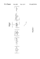
- FIG. 1 is a block diagram illustrating processing modules for providing curved surface reconstruction in accordance with the present invention.
- FIG. 2 is a flowchart illustrating a method of reconstructing curved surfaces in accordance with the present invention.
- FIG. 3 is a flowchart illustrating a method of generating reconstruction data in accordance with the present invention.
- FIG. 4 a is a flowchart illustrating a method of calculating resolution levels in accordance with the present invention.
- FIG. 4 b is a diagram illustrating a vector representing an edge chordal deviation in accordance with the present invention.
- FIG. 4 c is a diagram of a projected vector in screen space.
- FIG. 5 is a flowchart illustrating a method of subdividing polygons in accordance with the present invention.
- FIGS. 6 a and 6 c are diagrams illustrating prior art subdivisions
- FIGS. 6 b and 6 d are diagrams illustrating subdivisions in accordance with the present invention.
- FIG. 7 is a flowchart illustrating reconstructing a curved surface in accordance with the present invention.
- FIGS. 8 a - 8 t are diagrams of subdivision patterns for eliminating T-vertices in accordance with the present invention.
- FIG. 9 is an illustration of generating 10 Bezier control parameters from 3 edge splines in accordance with the present invention.
- FIG. 10 is an illustration of generating tangent vectors from surface normal data in accordance with the present invention.
- FIG. 1 is a block diagram illustrating processing modules for providing curved surface reconstruction in accordance with the present invention.
- the processing in accordance with the present invention can be executed by application-specific integrated circuits, by general-purpose processors, or any other known method of implementation of sequenced instructions.
- the methodology of the present invention is especially advantageous for implementation as ASICs, as the methodology does not require branch instructions that would otherwise complicate an ASIC implementation.
- FIG. 1 illustrates a graphics subsystem 124 , in which a surface representation generator 100 generates an object to be displayed on a computer display.
- the surface representation generator 100 can be any conventional source for three-dimensional objects to be used in CAD applications, gaming applications, or the like.
- Surface representations may include boundary representations, nonuniform rational b-splines, polygonal approximations, primitives, analytics, or procedural objects. As can be seen, any representational format may be used in accordance with the present invention.
- the object to be analyzed is described as comprising a series of triangles, but this description is exemplary is not intended to limit the application of the present invention to triangle-based graphics systems.
- a reconstruction data generator 104 converts the surface representation to a uniform representation. This is preferably accomplished by casting the surface representation into a control mesh. To generate a control mesh from the surface representation, known tessellation techniques are used to extract the polygon data from the surface representation.
- FIG. 2 is a flowchart illustrating a method of reconstructing curved surfaces in accordance with the present invention, and will be described in conjunction with FIG. 1 .
- reconstruction data is generated 204 from the tessellation data by the reconstruction data generator 104 .
- Reconstruction data is data used in accordance with the present invention for reconstructing curved surfaces, and is therefore maintained in memory associated with the reconstruction data generator 104 or centralized memory located elsewhere (not shown).
- the reconstruction data is additional to the polygon data typically contained in a control mesh.
- surface normal data for the polygons are generated 300 .
- surface hint data are stored, which indicate characteristics about the surface comprising the polygons.
- surface hint data includes edge data, sharpness data, and cubic spline data.
- a flag is set 304 to maintain that information for later reconstruction.
- a flag is set 308 to maintain this information. If an edge is smooth, a smooth flag is set.
- Cubic spline information is stored 312 for each original polygon edge to capture the curvature of a surface.
- Cubic spline information is preferably maintained by storing a head and tail tangent vector to be used to recreate the cubic spline via its Hermite representation. These Hermite cubic splines along each edge are then used to generate a Bezier triangular patch for each original polygon.
- reconstruction data enables the reconstruction of an accurate representation of the original surface.
- Other data provided in tessellation information can also be extracted to provide reconstruction information in accordance with the present invention.
- a resolution level generator 108 receives the control mesh and reconstruction data to calculate vertex-specific resolution levels for each polygon.
- Resolution levels determine whether and how much a polygon is subdivided. Subdividing a polygon provides higher resolution, as a subdivided polygon appears more smoothly curved and appears to have more detail upon rendering than a polygon that is not subdivided.
- a vertex-specific resolution level allows subdivision to occur precisely where it is needed. In contrast, conventional systems do not provide vertex-specific resolution levels, and thus do not tailor subdivision to those polygons that require it most.
- resolution levels may take four values, 0 (no subdivision), 1 (subdivide once), 2 (subdivide twice), and 3 (subdivide three times). For example, in FIG.
- FIG. 8 a resolution levels of all three vertices are 0. Therefore, the polygon (in this case, a triangle) is not subdivided.
- FIG. 8 d all three vertices have a resolution level of 1. Accordingly, the polygon is subdivided once into four smaller triangles, providing greater detail and curvature than the original triangle.
- FIG. 8 j the vertices are specified at a resolution level of 2. Thus, the polygon is subdivided twice to provide 16 triangles from the original triangle.
- FIG. 8 t has vertices specified at a resolution level of 3. Accordingly, the original polygon is subdivided three times, to generate 64 triangles.
- This subdivision provides the greatest amount of resolution, and is selected for surfaces that are very curved, and are positioned obliquely with respect to the camera direction, as discussed in more detail below.
- specifying the resolution levels of the vertices controls the amount of subdivision provided to a polygon, and therefore allows dynamic control over the amount of detail assigned to different components of an object.
- a chordal deviation vector for an edge 420 is generated 400 .
- the chordal deviation vector 424 is created from the midpoint of an edge 420 to the midpoint of a cubic spline 416 representing the surface of the polygon.
- This cubic spline 416 is taken from the cubic spline information derived from the control mesh as described above. There is one cubic spline 416 for each edge in the original control mesh.
- This vector 424 thus represents the projection outwards of the edge 420 of a polygon.
- the vector 324 is projected into screen space to determine a visibility factor for the edge 420 of the polygon.
- the visibility factor measures the amount of visibility of the edge 420 of the polygon when converted into screen space coordinates. For example, if the polygon represents part of the tip of the nose of a face that is facing the camera, the polygons comprising the tip have a low visibility factor because the curvature of the nose is not apparent when viewed directly. However, if face is turned toward a more profile angle, the visibility factor is high, because the curvature of the nose can be seen very clearly in screen space.
- the vector 424 is projected 404 into screen space 428 , as shown in FIG. 4 c .
- the length of the vector 424 in screen space 428 represents the amount of visibility of the edge 420 of the polygon when seen by the user.
- a resolution threshold is created to compare lengths of projected vectors against a threshold to determine 412 the amount of resolution to be assigned to the endpoints of the edge 420 defined by the vector 424 .
- a resolution threshold is chosen such that if the length of the projected vector does not exceed the threshold, a resolution level of 0, or no subdivision, is assigned to the endpoints of the edge 420 represented by the vector 424 . If the length of the projected vector 424 exceeds 1T but is less than 2T (where T is the resolution threshold), then a resolution level of 1 is assigned to the endpoints of the edge 420 , indicating that the polygon be subdivided once. If the length of the projected vector 424 exceeds 2T but is less than 3T, a resolution level of 2 is assigned to the endpoints of the edge 420 .
- a resolution level of 3 is assigned to the endpoints of the edge 420 .
- resolution levels can be adaptively determined for individual vertices of a polygon responsive to the visibility of the edge 420 of the polygon when displayed in screen space. Variations on a chosen resolution threshold value and consequent assignments of resolution levels can also be used in accordance with the present invention.
- an endpoint resolution level is generated 414 for all edges for which it is a part. This may provide different resolution levels for an endpoint depending on which polygon it is considered with.
- the maximum resolution level for an endpoint of an edge is selected 415 as the resolution level to be used for the endpoint. This ensures the highest quality appearing object will be generated by the present invention. However, an average of the resolution values or the minimum resolution value (providing faster speed) may also be used in accordance with the present invention.
- FIG. 6 a illustrates the T-vertex problem.
- triangle 605 adjacent to triangle 606 creates a T-vertex problem because the bases of triangles 601 of triangle 605 are split by triangles 602 of triangle 606 at points 604 . If rendered, this will generate visual artifacts.
- a subdivision optimizer 116 is provided to eliminate this recursive processing.
- the subdivision optimizer 116 comprises a look-up table stored in memory that maintains the subdivisions for every possible resolution level combination.
- any other data structure for storing information in an organized fashion that can be quickly retrieved may also be used in accordance with the present invention.
- the polygon subdivider 112 determines 500 the resolution levels of vertices of a polygon to be subdivided.
- the resolution level generator 108 preferably has previously determined the resolution levels, however, the resolution levels can be generated from any source.
- polygon subdivider 112 retrieves 504 a subdivision pattern stored in the subdivision optimizer 116 for the given resolution levels.
- the subdivision patterns are predesigned to eliminate T-vertex problems, thus eliminating the need to recursively fix T-vertex problems.
- the polygon subdivider 112 subdivides 508 the polygon responsive to the retrieved subdivision pattern.
- FIGS. 8 a- 8 t illustrate one embodiment of predesigned patterns covering all possible subdivisions in a system having four resolution levels (0-3).
- the vertex numbers of the subdivided triangles created are listed in vertex number boxes next to the subdivided triangle.
- the vertex numbers are identified in the reference triangle 800 illustrated on each sheet of the drawings.
- a representation of the reference triangle 800 is maintained by the subdivider 112 to allow efficient subdivision of a given triangle.
- the reference triangle 800 specifies all possible vertices of a subdivided triangle.
- FIG. 8 f four subdivided triangles are to be generated.
- the vertex numbers for the first subdivided triangle 801 are (0,1,5), and as shown in reference triangle 800 , those points of the reference triangle 800 can be connected to form triangle 801 .
- the other triangles 802 , 803 , 804 are computed similarly.
- the subdivision optimizer 116 can transmit the vertex numbers of the new polygons to the subdivider 112 , and the subdivider can subdivide the polygon by adding the polygons at the locations specified by the vertex numbers with reference to the reference triangle 800 .
- the subdivision optimizer 116 is only required to store the subdivision pattern and the associated vertex numbers of the polygons to be generated, thus minimizing the resources required to implement the subdivision optimizer 116 .
- the subdivision optimizer is a look-up table
- the size of the look-up table is greatly reduced through use of a reference triangle 800 .
- FIGS. 8 a- 8 t subdivision patterns for 20 possible combinations of resolution levels are stored. However, as each pattern has three degrees of rotation, all 64 possible cases are addressed by these 20 subdivision patterns. Storing only 20 patterns and providing rotation minimizes storage requirements; however, all 64 patterns could also be maintained in accordance with the present invention.
- the application of a subdivision pattern in this case, the pattern of FIG. 8 g , eliminates T-vertex problems by generating a subdivided polygon providing the required amount of subdivision without creating T-vertices.
- triangles 601 of triangle 605 are aligned with triangle 602 at point 604 , thus eliminating the T-vertex.
- FIG. 6 c illustrates a second T-vertex problem
- FIG. 6 d illustrates the subdivision pattern that eliminates the T-vertex problem.
- the base of triangle 612 is split by triangles 614 at points 616 .
- the base of triangle 612 is met with an equally solid base of triangle 614 .
- a single iteration is all that is required to generate T-vertex free polygonal combinations, saving processing power, time, and providing a higher quality visual representation.
- the single iteration methodology also allows the present invention to be implemented as dedicated hardware as the recursive processing of conventional systems is eliminated.
- FIG. 7 is a flowchart illustrating reconstructing a curved surface in accordance with the present invention.
- a polygon to be analyzed is received 700 by the curved surface reconstruction engine 116 .
- the polygon can be generated from the polygon subdivider 112 , or can be generated from a conventional source of polygons to be rendered by a renderer 120 .
- the position information of the vertices of the polygon are retrieved 704 . This information was stored, as discussed above, as part of the original polygonal information that accompanied the reconstruction data generated by the reconstruction data generator 104 .
- triangular Bezier patches (bicubic patches) are used to represent the curved surface represented by a polygon to provide a more accurate reconstruction of the surface due to the high flexibility of the Bezier patch.
- the Bezier triangle surface parameters are calculated from the edge spline data stored previously during the generation of reconstruction data step.
- a polygon 900 is comprised of 3 edge splines 901 , 902 , 903 . These splines (Hermite) are composed of two vertices, a head vertex and a tail vertex, for which the position information was stored previously.
- the surface normal data also stored previously, is used to generate the two tangents at each vertex (discussed below), a head tangent and tail tangent. This information is then used to convert the 3 edge splines 901 , 902 , 903 into 1 Bezier triangular patch.
- the equations listed in FIG. 9 are a preferred method of converting edge spline data into Bezier patch data; however other methods known to those of ordinary skill in the art may also be used in accordance with the present invention.
- the position information of the vertices is assigned to the three Bezier parameter fields for storing coordinates of the Bezier patch, as shown in Equations 905 , 908 , and 911 .
- the surface normal information previously stored as a part of the reconstruction data is retrieved 708 and used to generate 2 surface tangents for each surface normal.
- the surface normals 1001 , 1002 are used to generate tangent vectors 1003 , 1004 for each edge 901 , 902 , 903 of the received polygon.
- a first tangent vector 1003 is generated responsive to Equation 1005 and a second tangent vector 1004 is generated responsive to Equation 1006 , where t 0 is the first tangent vector 1003 , t 0 is the second tangent vector, n 0 is the first surface normal at the endpoint of the tail of the edge 901 , 902 , 903 , n 1 is the surface normal at the head of the edge 901 , 902 , 903 , the symbol “ ⁇ circumflex over ( ) ⁇ ” indicates is the conventional normalize operator, which takes a vector of arbitrary length and generates a vector with unit length in the same direction, and e 0 is the edge 901 , 902 , 903 being analyzed.
- all of the vectors are computed as 3D vectors.
- the data for representing the 2 surface tangents for each edge spline 901 , 902 , 903 are assigned to 2 Bezier parameter fields responsive to equations 906 , 907 , 909 , 910 , 912 , 913 .
- the distance the Bezier patch will project from the plane containing the endpoints of the patch is computed responsive to equation 914 , and assigned to the last Bezier parameter field, giving the last of the 10 Bezier control points.
- Other equations for converting the vertex, cubic spline, and surface normal information into 10 Bezier control parameters would be considered to be within the scope of the present invention.
- the present invention also examines the flags set during the reconstruction data generation.
- the flags indicate whether the surface to be reconstructed has a sharp point, a hard edge, is continuously smooth, or has other surface qualities. That information allows the generation of a curved surface represented by the Bezier triangle that accurately reflects the surface of the original object. More specifically, the flags are used to control the continuity of neighboring Bezier triangles. If the smooth flag is set, normals are matched across adjacent Bezier triangles. If a sharp edge or point is set, normals are not shared along edges or points across adjacent Bezier triangles, resulting in a sharp edge.
- the reconstruction data could be used to generate parameters for alternate mathematical representations in accordance with the present invention. Once the Bezier patch for each polygon has been generated, the Bezier patch is evaluated at all new vertices of polygons generated by subdivision, and these new polygons are transmitted to the renderer 120 , which then renders the object for display to the user.
- the reconstructed version of the object may have even more detail than the original representation (if, for example, a polygonal approximation was used as the original surface representation) in accordance with the present invention, thus providing a higher quality reconstructed object than the original object from which the reconstructed object was based.
- the circuitry of the present invention executes the above-described methodology preferably each time a camera angle shifts, to dynamically add or subtract polygons from the viewed image as appropriate.
- the processing of images at run-time can be accomplished effectively and efficiently.
- the time required to process each object is greatly minimized. Accordingly, even those systems implementing the present invention with a general purpose processor can still provide on-the-fly curved surface rendering quickly at run-time.
Abstract
Description
Claims (24)
Priority Applications (4)
| Application Number | Priority Date | Filing Date | Title |
|---|---|---|---|
| US09/466,540 US6462738B1 (en) | 1999-04-26 | 1999-12-17 | Curved surface reconstruction |
| EP00303394A EP1049049B1 (en) | 1999-04-26 | 2000-04-20 | Curved surface reconstruction at plural resolution levels |
| DE60032832T DE60032832T2 (en) | 1999-04-26 | 2000-04-20 | Illustration of a curved surface in several resolutions |
| JP2000126069A JP2001052194A (en) | 1999-04-26 | 2000-04-26 | Reconfiguration for curved surface |
Applications Claiming Priority (2)
| Application Number | Priority Date | Filing Date | Title |
|---|---|---|---|
| US13118899P | 1999-04-26 | 1999-04-26 | |
| US09/466,540 US6462738B1 (en) | 1999-04-26 | 1999-12-17 | Curved surface reconstruction |
Publications (1)
| Publication Number | Publication Date |
|---|---|
| US6462738B1 true US6462738B1 (en) | 2002-10-08 |
Family
ID=26829222
Family Applications (1)
| Application Number | Title | Priority Date | Filing Date |
|---|---|---|---|
| US09/466,540 Expired - Fee Related US6462738B1 (en) | 1999-04-26 | 1999-12-17 | Curved surface reconstruction |
Country Status (4)
| Country | Link |
|---|---|
| US (1) | US6462738B1 (en) |
| EP (1) | EP1049049B1 (en) |
| JP (1) | JP2001052194A (en) |
| DE (1) | DE60032832T2 (en) |
Cited By (16)
| Publication number | Priority date | Publication date | Assignee | Title |
|---|---|---|---|---|
| US20020063710A1 (en) * | 2000-09-05 | 2002-05-30 | Yoshihiko Hirota | Image processing apparatus and image processing method |
| US6664960B2 (en) * | 2001-05-10 | 2003-12-16 | Ati Technologies Inc. | Apparatus for processing non-planar video graphics primitives and associated method of operation |
| US20040085312A1 (en) * | 2002-11-04 | 2004-05-06 | Buchner Brian A. | Method and apparatus for triangle tessellation |
| US20040090437A1 (en) * | 2002-11-12 | 2004-05-13 | Akira Uesaki | Curved surface image processing apparatus and curved surface image processing method |
| US6940503B2 (en) * | 2001-05-10 | 2005-09-06 | Ati International Srl | Method and apparatus for processing non-planar video graphics primitives |
| US20060139348A1 (en) * | 2003-12-26 | 2006-06-29 | Tsuyoshi Harada | Method for approximating and displaying three-dimensional cad data, and method thereof |
| US20080024490A1 (en) * | 2006-07-28 | 2008-01-31 | Microsoft Corporation | Real-time GPU rendering of piecewise algebraic surfaces |
| US20100085359A1 (en) * | 2008-10-03 | 2010-04-08 | Microsoft Corporation | Surface normal reconstruction from a single image |
| US20100266216A1 (en) * | 2009-04-15 | 2010-10-21 | Samsung Electronics Co., Ltd. | Progressive mesh decoding apparatus and method |
| CN101872488B (en) * | 2009-04-27 | 2012-05-16 | 鸿富锦精密工业(深圳)有限公司 | Curved surface rendering system and method |
| CN103606193A (en) * | 2013-11-29 | 2014-02-26 | 中国科学院深圳先进技术研究院 | Self-adaptive subdivision method and device |
| US20140063013A1 (en) * | 2012-08-30 | 2014-03-06 | Qualcomm Incorporated | Stitching for primitives in graphics processing |
| US9082204B2 (en) | 2012-08-30 | 2015-07-14 | Qualcomm Incorporated | Storage structures for stitching primitives in graphics processing |
| US9142060B2 (en) | 2012-08-30 | 2015-09-22 | Qualcomm Incorporated | Computation reduced tessellation |
| US9147288B1 (en) * | 2006-11-08 | 2015-09-29 | Lucasfilm Entertainment Company Ltd. | Subdivision of surfaces approximation |
| US20160187866A1 (en) * | 2014-10-23 | 2016-06-30 | Fanuc Corporation | Numerical control apparatus |
Families Citing this family (28)
| Publication number | Priority date | Publication date | Assignee | Title |
|---|---|---|---|---|
| AU2002230169A1 (en) * | 2002-02-06 | 2003-09-02 | Digital Process Ltd. | Three-dimensional shape displaying program, three-dimensional shae displaying method, and three-dimensional shape displaying device |
| US20060080072A1 (en) * | 2003-03-12 | 2006-04-13 | Computer Associates Think, Inc. | Optimized rendering of dynamic moving bodies |
| US8471852B1 (en) | 2003-05-30 | 2013-06-25 | Nvidia Corporation | Method and system for tessellation of subdivision surfaces |
| US7408548B2 (en) * | 2005-06-30 | 2008-08-05 | Microsoft Corporation | Triangulating procedural geometric objects |
| US8571346B2 (en) | 2005-10-26 | 2013-10-29 | Nvidia Corporation | Methods and devices for defective pixel detection |
| US7750956B2 (en) | 2005-11-09 | 2010-07-06 | Nvidia Corporation | Using a graphics processing unit to correct video and audio data |
| US8588542B1 (en) | 2005-12-13 | 2013-11-19 | Nvidia Corporation | Configurable and compact pixel processing apparatus |
| US8737832B1 (en) | 2006-02-10 | 2014-05-27 | Nvidia Corporation | Flicker band automated detection system and method |
| JP5007991B2 (en) * | 2006-02-13 | 2012-08-22 | 株式会社ディジタルメディアプロフェッショナル | Rendering device for subdivision curved surface drawing |
| CN100437642C (en) * | 2006-03-27 | 2008-11-26 | 腾讯科技(深圳)有限公司 | Pre-process method of searching model geometric space outline |
| US8594441B1 (en) | 2006-09-12 | 2013-11-26 | Nvidia Corporation | Compressing image-based data using luminance |
| US8723969B2 (en) | 2007-03-20 | 2014-05-13 | Nvidia Corporation | Compensating for undesirable camera shakes during video capture |
| US8724895B2 (en) | 2007-07-23 | 2014-05-13 | Nvidia Corporation | Techniques for reducing color artifacts in digital images |
| US8570634B2 (en) | 2007-10-11 | 2013-10-29 | Nvidia Corporation | Image processing of an incoming light field using a spatial light modulator |
| US9177368B2 (en) | 2007-12-17 | 2015-11-03 | Nvidia Corporation | Image distortion correction |
| US8698908B2 (en) | 2008-02-11 | 2014-04-15 | Nvidia Corporation | Efficient method for reducing noise and blur in a composite still image from a rolling shutter camera |
| US9379156B2 (en) | 2008-04-10 | 2016-06-28 | Nvidia Corporation | Per-channel image intensity correction |
| US8373718B2 (en) | 2008-12-10 | 2013-02-12 | Nvidia Corporation | Method and system for color enhancement with color volume adjustment and variable shift along luminance axis |
| US8749662B2 (en) * | 2009-04-16 | 2014-06-10 | Nvidia Corporation | System and method for lens shading image correction |
| US8698918B2 (en) | 2009-10-27 | 2014-04-15 | Nvidia Corporation | Automatic white balancing for photography |
| US9401046B2 (en) * | 2011-02-07 | 2016-07-26 | Intel Corporation | Micropolygon splatting |
| US8803885B1 (en) | 2011-09-07 | 2014-08-12 | Infragistics, Inc. | Method for evaluating spline parameters for smooth curve sampling |
| US9798698B2 (en) | 2012-08-13 | 2017-10-24 | Nvidia Corporation | System and method for multi-color dilu preconditioner |
| US9508318B2 (en) | 2012-09-13 | 2016-11-29 | Nvidia Corporation | Dynamic color profile management for electronic devices |
| US9307213B2 (en) | 2012-11-05 | 2016-04-05 | Nvidia Corporation | Robust selection and weighting for gray patch automatic white balancing |
| US9418400B2 (en) | 2013-06-18 | 2016-08-16 | Nvidia Corporation | Method and system for rendering simulated depth-of-field visual effect |
| US9826208B2 (en) | 2013-06-26 | 2017-11-21 | Nvidia Corporation | Method and system for generating weights for use in white balancing an image |
| US9756222B2 (en) | 2013-06-26 | 2017-09-05 | Nvidia Corporation | Method and system for performing white balancing operations on captured images |
Citations (5)
| Publication number | Priority date | Publication date | Assignee | Title |
|---|---|---|---|---|
| JPS6383871A (en) | 1986-09-27 | 1988-04-14 | Sony Corp | Shadow display method |
| US5602979A (en) * | 1993-08-27 | 1997-02-11 | Apple Computer, Inc. | System and method for generating smooth low degree polynomial spline surfaces over irregular meshes |
| EP0996094A1 (en) | 1998-04-09 | 2000-04-26 | Sony Computer Entertainment Inc. | Image processing apparatus and image processing method, program providing medium, and data providing medium |
| US6201881B1 (en) | 1997-05-27 | 2001-03-13 | International Business Machines Corporation | Embedding information in three-dimensional geometric model |
| US6222553B1 (en) * | 1997-08-04 | 2001-04-24 | Pixar Animation Studios | Hybrid subdivision in computer graphics |
-
1999
- 1999-12-17 US US09/466,540 patent/US6462738B1/en not_active Expired - Fee Related
-
2000
- 2000-04-20 EP EP00303394A patent/EP1049049B1/en not_active Expired - Lifetime
- 2000-04-20 DE DE60032832T patent/DE60032832T2/en not_active Expired - Lifetime
- 2000-04-26 JP JP2000126069A patent/JP2001052194A/en active Pending
Patent Citations (5)
| Publication number | Priority date | Publication date | Assignee | Title |
|---|---|---|---|---|
| JPS6383871A (en) | 1986-09-27 | 1988-04-14 | Sony Corp | Shadow display method |
| US5602979A (en) * | 1993-08-27 | 1997-02-11 | Apple Computer, Inc. | System and method for generating smooth low degree polynomial spline surfaces over irregular meshes |
| US6201881B1 (en) | 1997-05-27 | 2001-03-13 | International Business Machines Corporation | Embedding information in three-dimensional geometric model |
| US6222553B1 (en) * | 1997-08-04 | 2001-04-24 | Pixar Animation Studios | Hybrid subdivision in computer graphics |
| EP0996094A1 (en) | 1998-04-09 | 2000-04-26 | Sony Computer Entertainment Inc. | Image processing apparatus and image processing method, program providing medium, and data providing medium |
Cited By (28)
| Publication number | Priority date | Publication date | Assignee | Title |
|---|---|---|---|---|
| US7158134B2 (en) * | 2000-09-05 | 2007-01-02 | Minolta Co., Ltd. | Image processing apparatus and image processing method |
| US20020063710A1 (en) * | 2000-09-05 | 2002-05-30 | Yoshihiko Hirota | Image processing apparatus and image processing method |
| US6664960B2 (en) * | 2001-05-10 | 2003-12-16 | Ati Technologies Inc. | Apparatus for processing non-planar video graphics primitives and associated method of operation |
| US6940503B2 (en) * | 2001-05-10 | 2005-09-06 | Ati International Srl | Method and apparatus for processing non-planar video graphics primitives |
| US20040085312A1 (en) * | 2002-11-04 | 2004-05-06 | Buchner Brian A. | Method and apparatus for triangle tessellation |
| US8482559B2 (en) * | 2002-11-04 | 2013-07-09 | Ati Technologies Ulc | Method and apparatus for triangle tessellation |
| US7212205B2 (en) | 2002-11-12 | 2007-05-01 | Matsushita Electric Industrial Co., Ltd. | Curved surface image processing apparatus and curved surface image processing method |
| US20040090437A1 (en) * | 2002-11-12 | 2004-05-13 | Akira Uesaki | Curved surface image processing apparatus and curved surface image processing method |
| US7295202B2 (en) * | 2003-12-26 | 2007-11-13 | Toyota Jidosha Kabushiki Kaisha | System for approximating and displaying three dimensional CAD data, and system for executing method thereof |
| US20060139348A1 (en) * | 2003-12-26 | 2006-06-29 | Tsuyoshi Harada | Method for approximating and displaying three-dimensional cad data, and method thereof |
| US7924278B2 (en) | 2006-07-28 | 2011-04-12 | Microsoft Corporation | Real-time GPU rendering of piecewise algebraic surfaces |
| US20080024490A1 (en) * | 2006-07-28 | 2008-01-31 | Microsoft Corporation | Real-time GPU rendering of piecewise algebraic surfaces |
| US9147288B1 (en) * | 2006-11-08 | 2015-09-29 | Lucasfilm Entertainment Company Ltd. | Subdivision of surfaces approximation |
| US20100085359A1 (en) * | 2008-10-03 | 2010-04-08 | Microsoft Corporation | Surface normal reconstruction from a single image |
| US8928660B2 (en) | 2009-04-15 | 2015-01-06 | Samsung Electronics Co., Ltd. | Progressive mesh decoding apparatus and method |
| US20100266216A1 (en) * | 2009-04-15 | 2010-10-21 | Samsung Electronics Co., Ltd. | Progressive mesh decoding apparatus and method |
| CN101872488B (en) * | 2009-04-27 | 2012-05-16 | 鸿富锦精密工业(深圳)有限公司 | Curved surface rendering system and method |
| US20140063013A1 (en) * | 2012-08-30 | 2014-03-06 | Qualcomm Incorporated | Stitching for primitives in graphics processing |
| CN104584082A (en) * | 2012-08-30 | 2015-04-29 | 高通股份有限公司 | Stitching for primitives in graphics processing |
| US9076260B2 (en) * | 2012-08-30 | 2015-07-07 | Qualcomm Incorporated | Stitching for primitives in graphics processing |
| US9082204B2 (en) | 2012-08-30 | 2015-07-14 | Qualcomm Incorporated | Storage structures for stitching primitives in graphics processing |
| US9142060B2 (en) | 2012-08-30 | 2015-09-22 | Qualcomm Incorporated | Computation reduced tessellation |
| CN104584082B (en) * | 2012-08-30 | 2016-08-31 | 高通股份有限公司 | The stitching of the primitive in graphics process |
| CN103606193A (en) * | 2013-11-29 | 2014-02-26 | 中国科学院深圳先进技术研究院 | Self-adaptive subdivision method and device |
| CN103606193B (en) * | 2013-11-29 | 2016-10-12 | 中国科学院深圳先进技术研究院 | A kind of self-adapting subdividing method and device |
| US20160187866A1 (en) * | 2014-10-23 | 2016-06-30 | Fanuc Corporation | Numerical control apparatus |
| US10429814B2 (en) * | 2014-10-23 | 2019-10-01 | Fanuc Corporation | Numerical control apparatus |
| US10684604B2 (en) | 2014-10-23 | 2020-06-16 | Fanuc Corporation | Numerical control apparatus enabling specification of a circular arc shape movement trajectory |
Also Published As
| Publication number | Publication date |
|---|---|
| EP1049049A3 (en) | 2003-08-13 |
| DE60032832D1 (en) | 2007-02-22 |
| EP1049049A2 (en) | 2000-11-02 |
| DE60032832T2 (en) | 2007-11-29 |
| JP2001052194A (en) | 2001-02-23 |
| EP1049049B1 (en) | 2007-01-10 |
Similar Documents
| Publication | Publication Date | Title |
|---|---|---|
| US6462738B1 (en) | Curved surface reconstruction | |
| US8115767B2 (en) | Computer graphics shadow volumes using hierarchical occlusion culling | |
| US5745666A (en) | Resolution-independent method for displaying a three-dimensional model in two-dimensional display space | |
| US5812141A (en) | Method and apparatus for an adaptive texture mapping controller | |
| US6532013B1 (en) | System, method and article of manufacture for pixel shaders for programmable shading | |
| Zwicker et al. | EWA splatting | |
| US6791540B1 (en) | Image processing apparatus | |
| US7239319B2 (en) | Rendering outline fonts | |
| US7924278B2 (en) | Real-time GPU rendering of piecewise algebraic surfaces | |
| Boubekeur et al. | Phong tessellation | |
| EP0553973A2 (en) | Computer graphics display method and system with shadow generation | |
| US20070018988A1 (en) | Method and applications for rasterization of non-simple polygons and curved boundary representations | |
| US8269770B1 (en) | Tessellation of trimmed parametric surfaces by walking the surface | |
| US7843463B1 (en) | System and method for bump mapping setup | |
| US8576225B2 (en) | Seamless fracture in a production pipeline | |
| US6184893B1 (en) | Method and system for filtering texture map data for improved image quality in a graphics computer system | |
| US20040207634A1 (en) | Full-scene anti-aliasing method and system | |
| Pabst et al. | Ray casting of trimmed NURBS surfaces on the GPU | |
| US20020118212A1 (en) | Shading polygons from a three-dimensional model | |
| Fischer et al. | Illustrative display of hidden iso-surface structures | |
| JPH05290174A (en) | Graphics work station for handling structure of 3-dimensional model and method for generating 3-dimensional graphics picture of structure of model | |
| US8274513B1 (en) | System, method, and computer program product for obtaining a boundary attribute value from a polygon mesh, during voxelization | |
| Baer et al. | Hardware-accelerated Stippling of Surfaces derived from Medical Volume Data. | |
| Ragragui et al. | Revolution mapping with bump mapping support | |
| JP2809955B2 (en) | Graphics workstation and method for generating three-dimensional graphics image |
Legal Events
| Date | Code | Title | Description |
|---|---|---|---|
| AS | Assignment |
Owner name: SPATIAL TECHNOLOGY, INC., CALIFORNIA Free format text: ASSIGNMENT OF ASSIGNORS INTEREST;ASSIGNOR:KATO, SAUL S.;REEL/FRAME:010483/0585 Effective date: 19991216 |
|
| AS | Assignment |
Owner name: SPATIAL COMPONENTS, LLC, COLORADO Free format text: ASSIGNMENT OF ASSIGNORS INTEREST;ASSIGNOR:SPATIAL TECHNOLOGY, INC.;REEL/FRAME:012043/0162 Effective date: 20001114 |
|
| CC | Certificate of correction | ||
| AS | Assignment |
Owner name: SPATIAL CORP., COLORADO Free format text: ASSIGNMENT OF ASSIGNORS INTEREST;ASSIGNOR:SPATIAL COMPONENTS, LLC;REEL/FRAME:013804/0593 Effective date: 20030213 |
|
| CC | Certificate of correction | ||
| AS | Assignment |
Owner name: SPATIAL COMPONENTS, LLC, COLORADO Free format text: ASSIGNMENT OF ASSIGNORS INTEREST;ASSIGNOR:SPATIAL TECHNOLOGY, INC.;REEL/FRAME:014532/0345 Effective date: 20001114 |
|
| FPAY | Fee payment |
Year of fee payment: 4 |
|
| FPAY | Fee payment |
Year of fee payment: 8 |
|
| REMI | Maintenance fee reminder mailed | ||
| LAPS | Lapse for failure to pay maintenance fees | ||
| STCH | Information on status: patent discontinuation |
Free format text: PATENT EXPIRED DUE TO NONPAYMENT OF MAINTENANCE FEES UNDER 37 CFR 1.362 |
|
| FP | Lapsed due to failure to pay maintenance fee |
Effective date: 20141008 |