US6453654B1 - Apparatus for conditioning crop materials - Google Patents
Apparatus for conditioning crop materials Download PDFInfo
- Publication number
- US6453654B1 US6453654B1 US09/873,804 US87380401A US6453654B1 US 6453654 B1 US6453654 B1 US 6453654B1 US 87380401 A US87380401 A US 87380401A US 6453654 B1 US6453654 B1 US 6453654B1
- Authority
- US
- United States
- Prior art keywords
- conditioning
- reimpactor
- flail
- conditioner
- crop
- Prior art date
- Legal status (The legal status is an assumption and is not a legal conclusion. Google has not performed a legal analysis and makes no representation as to the accuracy of the status listed.)
- Expired - Fee Related
Links
Images


Classifications
-
- A—HUMAN NECESSITIES
- A01—AGRICULTURE; FORESTRY; ANIMAL HUSBANDRY; HUNTING; TRAPPING; FISHING
- A01D—HARVESTING; MOWING
- A01D43/00—Mowers combined with apparatus performing additional operations while mowing
- A01D43/10—Mowers combined with apparatus performing additional operations while mowing with means for crushing or bruising the mown crop
Definitions
- the present invention relates generally to flail-type crop conditioners for pull-type crop-treating equipment in the agricultural industry, and particularly to a flail-type conditioner that employs an improved reimpactor for redirecting treated crop material to the conditioning unit for additional treatment.
- stalky plant material such as alfalfa, clover, or the like
- stalky plant material such as alfalfa, clover, or the like
- Flail conditioning causes the plant stems to be even more severely crushed, with more of the waxy covering removed.
- the various levels of conditioning to which plant materials are subjected have a direct affect on the drying rate.
- the instant invention relates to an improved reimpactor—a mechanism in a crop conditioning apparatus for redirecting materials already subjected to conditioning back to the conditioning unit for additional treatment.
- An example of a type of reimpactor is shown in U.S. Pat. No. 6,101,797, issued to Richard Koegel et al. on Aug. 15, 2000. Note, for example, in FIG. 3 thereof that guide elements 51 and 52 redirect the flow of crop materials in this maceration apparatus into the rotating impact rotor 23 .
- a macerator is somewhat different from a conditioner in that it is intended to even more severely crush the crop materials.
- ATERNA 500 Another example of a reimpactor is used in a commercial flail conditioner sold by Kuhn and identified as the “ALTERNA 500”.
- An adjustable bar with protruding fixed finger elements, all extending in the same direction, is affixed above the flail. The bar may be rotated to move the finger elements into and out of the flow path of the crop material, thus adjusting the amount of crop material that is redirected into the flail for additional treatment.
- Both the Koegel and Kuhn devices are rigid and thus in actual use become bent, deformed and broken when stones and other solid objects are passed through the apparatus. If, for example, a stone is fed into the conditioner and bends one of the fingers into the path of a flail element, either the finger or the flail element, or both, will likely be broken, and possibly even additional damage will result.
- the reimpactor is constructed partially of a shock-absorbent material, such as urethane, so that it may retain its shape even upon impact with foreign objects such as stones or misshapen flails, thus displaying significant longevity and durability characteristics.
- FIG. 1 is a top plan view of a disc mower flail-conditioner to which the instant invention has been applied;
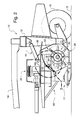
- FIG. 2 is a vertical section taken along line 2 — 2 of FIG. 1 with the area of the invention marked by circle area 3 ;
- FIG. 3 is circle area 3 of FIG. 2 enlarged
- FIG. 4 is a plan view of that portion of FIG. 3 indicated by the line 4 — 4 of FIG. 3 with one reimpactor module removed and the shock-absorbent portion of the two adjacent modules broken away;
- FIG. 5 is an enlarged sectional view taken along line 5 — 5 of FIG. 4 (reoriented to fit the page);
- FIG. 6 is a plan view of a reimpactor module
- FIG. 7 is an elevation view of FIG. 6, from the side 7 — 7 thereof;
- FIG. 8 is a sectional view of the module taken along line 8 — 8 of FIG. 7;
- FIG. 9 is a perspective view of the one piece multiple tine casting
- FIG. 10 is an enlarged schematic view similar to FIG. 3 showing a second reimpactor in position
- FIG. 11 is a view similar to FIG. 3 but showing the prior art reimpactor.
- FIG. 12 is an elevational view of the prior art reimpactor taken on line 12 — 12 of FIG. 11 .
- FIGS. 1 and 2 a hay-harvesting machine, commonly referred to as the pull-type flail-conditioner, incorporating the principles of the instant invention can best be seen.
- Any “left” and “right” references are used as a matter of convenience and are determined by standing at the rear of the machine, facing the forward end, in the direction of travel.
- Flail-conditioner 10 is provided with a frame 12 adapted for mobile movement over the ground G by wheels 13 rotatably mounted thereon.
- the frame 12 is provided with a pivotal drawbar 14 that extends forwardly therefrom for connection to a prime mover, such as a tractor T, in a conventional manner.
- the frame 12 supports a header 15 by flotation linkage 16 for a generally vertical movement relative to the ground G as is conventionally known.
- the header 15 includes a conventional disc cutterbar 17 operable to sever standing crop material from the ground G and convey it rearwardly to the conditioning mechanism 20 .
- the drive mechanism 22 is supported from the drawbar 14 and the frame 12 to transfer rotational power from the prime mover in conventional manner to the operable elements of conditioner 10 .
- the conditioning unit 30 is comprised of an elongated drum 32 rotatable about shaft 34 that is generally transverse to the direction of travel of conditioner 10 .
- the flail segments 40 are comprised of a plurality of flail elements 42 which are rigidly affixed to member 44 .
- the flail segments are pivotable about shaft 46 to the extent that they come into contact with drum 32 (see FIG. 10 ).
- the flail segments may be mounted on drum 32 in various configurations; however, the best arrangement seems to be staggered around the circumference of drum 32 such that they extend from one end of the drum to the other in a spiral fashion.
- the conditioning unit 30 sits within a flail-conditioning chamber 50 formed by curved sheet 52 , end sheets 54 (FIG. 1 ), and the ground G. There is a forward entrance into the flail-conditioning chamber above and to the rear of disc cutterbar 17 , an exit below and to the rear of baffle 56 . Curved sheet 52 and baffle 56 are generally the same length as conditioning unit 30 and extend between end sheets 54 . The baffle 56 is adjustably mounted to move into and out of the flow of condition crop material to control, among other things, the thickness of the windrow.
- Reimpactor 60 is affixed to the inside of curved sheet 52 .
- the conditioner 10 moves through the field, crop is engaged to by disc cutterbar 17 and severed from the ground. It then flows rearwardly into the conditioning unit 30 where it is broken and crushed in a normal manner.
- the crop material is treated it is thrown upwardly into and along curved sheet 52 where it engages reimpactor 60 .
- the reimpactor redirects the crop material to the conditioning unit for additional treatment, and then returned to curved sheet 52 , finally exiting onto the ground for drying.
- the reimpactor 60 may vary in construction and methods of incorporation into the flail-conditioner. The best mode is what is shown herein specifically; however, one of skill in the art will readily see alternatives and modifications. Attention is directed generally to FIGS. 3-8 and 10 , but initially to FIG. 5 which shows that reimpactor 60 has a general triangular cross-section. FIGS. 6 and 7 show that reimpactor 60 has slots 62 therein which accommodate flail elements 42 . Thus, referring briefly to FIG. 3, it can be seen that reimpactor 60 extends into and through the circular path 62 created by the tips of flail elements 42 , while the flail elements 42 pass through slots 62 . This arrangement assures that the crop material does not build up in front of, or merely bypass, the reimpactor.
- reimpactor 60 is constructed in segments 66 , each containing five slots.
- the material chosen for the main body of the reimpactor is polyurethane; however, other durable, elastic shock-absorbing materials such as, for example, rubber, are available and could fulfill this purpose quite adequately.
- the triangular shaped portion of the reimpactor is formed on a metal plate 68 having, in this particular embodiment, three flanges ( 72 , 73 and 74 ).
- An elongated plate 70 is mounted to curved sheet 52 and has therein regularly spaced slots 75 into which flanges 72 - 74 may be inserted.
- reimpactor 60 By then fitting the flanges and plate 68 properly on plate 70 , reimpactor 60 will be in the position previously described and may be fixed there by the application of bolts 78 . In this manner multiple reimpactor segments may be affixed to plate 70 along the longitudinal dimension of curved sheet 52 as shown in FIG. 4 .
- the size of the reimpactor, in this embodiment the height of the triangular cross-section, may, of course, vary. It is of primary importance that the height be adequate to extend into the path of the flail elements as previously described.
- FIG. 9 shows the flail segments 40 as having five finger-like elements 42 .
- This is a convenient structure for casting and, when considered in conjunction with a five-slotted reimpactor, presents a very convenient structure for retrofitting the instant invention onto older machines, as well as constructing new machines.
- the five-finger structure additionally allows greater tolerance between the flail elements 42 and the sides of the slots 62 , i.e., allows for larger slots. Cost effectiveness is thus improved.
- FIGS. 11 and 12 show one prior art device that employs the rigid reimpactor.
- the flail-conditioner includes finger-like elements 80 which generate a path 86 at the tips thereof, which pass through rods 82 rigidly affixed to shaft 88 .
- the shaft 88 may be rotated from a position 89 where there is no reimpaction provided, to position 90 . All of the elements of the reimpactor are rigid and may thus be broken, bent or deformed if contacted by a stone or other solid object during operation.
Landscapes
- Life Sciences & Earth Sciences (AREA)
- Environmental Sciences (AREA)
- Soil Working Implements (AREA)
Abstract
Description
Claims (20)
Priority Applications (1)
| Application Number | Priority Date | Filing Date | Title |
|---|---|---|---|
| US09/873,804 US6453654B1 (en) | 2001-06-04 | 2001-06-04 | Apparatus for conditioning crop materials |
Applications Claiming Priority (1)
| Application Number | Priority Date | Filing Date | Title |
|---|---|---|---|
| US09/873,804 US6453654B1 (en) | 2001-06-04 | 2001-06-04 | Apparatus for conditioning crop materials |
Publications (1)
| Publication Number | Publication Date |
|---|---|
| US6453654B1 true US6453654B1 (en) | 2002-09-24 |
Family
ID=25362355
Family Applications (1)
| Application Number | Title | Priority Date | Filing Date |
|---|---|---|---|
| US09/873,804 Expired - Fee Related US6453654B1 (en) | 2001-06-04 | 2001-06-04 | Apparatus for conditioning crop materials |
Country Status (1)
| Country | Link |
|---|---|
| US (1) | US6453654B1 (en) |
Cited By (13)
| Publication number | Priority date | Publication date | Assignee | Title |
|---|---|---|---|---|
| US20040168422A1 (en) * | 2001-06-05 | 2004-09-02 | Jean-Baptiste Ligouy | Processing element for agricultural machines |
| US20070068130A1 (en) * | 2003-05-23 | 2007-03-29 | Kuhn S.A. | Device for processing fodder |
| US20110202581A1 (en) * | 2000-12-07 | 2011-08-18 | Kazar Michael L | Method and system for responding to file system requests |
| US20120090288A1 (en) * | 2009-07-08 | 2012-04-19 | Kuhn S.A. | Plant mower-conditioner comprising a device for uniformly distributing plants thrown back to the ground |
| CN106612912A (en) * | 2016-12-29 | 2017-05-10 | 纪小坤 | Harvester with adjustable cutting blades and fixed lower header |
| CN106612896A (en) * | 2016-12-29 | 2017-05-10 | 纪小坤 | Harvester with hoisting type lower header and capable of crushing straws |
| CN106612911A (en) * | 2016-12-29 | 2017-05-10 | 纪小坤 | Harvester with protective ladder and lifting lower header capable of evenly chopping straws and preventing smashed straws from splashing |
| CN106612910A (en) * | 2016-12-29 | 2017-05-10 | 纪小坤 | Harvester with fixed lower cutting header and capable of evenly smashing straws |
| CN106664952A (en) * | 2016-12-29 | 2017-05-17 | 纪小坤 | Harvester with lifting lower header capable of crushing straws and preventing spatter of crushed straws |
| CN106852218A (en) * | 2016-12-29 | 2017-06-16 | 纪小坤 | The harvester of the lift lower cutting table that crushed stalk is uniform and breakage-proof stalk splashes |
| US20180213722A1 (en) * | 2017-01-28 | 2018-08-02 | Green Gold Development, Llc | Multipurpose leaf crop harvesting apparatus and processing method |
| US11096329B2 (en) | 2019-05-31 | 2021-08-24 | Deere & Company | Crop conditioner hood with integrated swathboard |
| US11234369B2 (en) * | 2017-03-31 | 2022-02-01 | Kverneland Group Kerteminde As | Mower-conditioner with a variable speed ratio |
Citations (8)
| Publication number | Priority date | Publication date | Assignee | Title |
|---|---|---|---|---|
| US3722191A (en) * | 1972-02-25 | 1973-03-27 | Gehl Co | Windrowing means for agricultural machine |
| US3835629A (en) * | 1973-03-08 | 1974-09-17 | Allis Chalmers | Crop conditioners |
| US4182099A (en) * | 1977-11-21 | 1980-01-08 | Deere & Company | Impeller mower-conditioner rotor |
| US4270338A (en) * | 1979-12-10 | 1981-06-02 | Sperry Corporation | Crop harvesting machine |
| US4637201A (en) * | 1984-07-24 | 1987-01-20 | Hesston Corporation | Wide-cut windrower-conditioner having uniform crop distribution and conditioning |
| US5894716A (en) * | 1996-06-28 | 1999-04-20 | New Holland North America, Inc. | Apparatus for macerating plant material |
| US5950406A (en) | 1996-06-28 | 1999-09-14 | New Holland North America, Inc. | Method and apparatus for macerating plant material |
| US6029432A (en) * | 1997-08-04 | 2000-02-29 | New Holland North America, Inc. | Apparatus for treating plant material |
-
2001
- 2001-06-04 US US09/873,804 patent/US6453654B1/en not_active Expired - Fee Related
Patent Citations (9)
| Publication number | Priority date | Publication date | Assignee | Title |
|---|---|---|---|---|
| US3722191A (en) * | 1972-02-25 | 1973-03-27 | Gehl Co | Windrowing means for agricultural machine |
| US3835629A (en) * | 1973-03-08 | 1974-09-17 | Allis Chalmers | Crop conditioners |
| US4182099A (en) * | 1977-11-21 | 1980-01-08 | Deere & Company | Impeller mower-conditioner rotor |
| US4270338A (en) * | 1979-12-10 | 1981-06-02 | Sperry Corporation | Crop harvesting machine |
| US4637201A (en) * | 1984-07-24 | 1987-01-20 | Hesston Corporation | Wide-cut windrower-conditioner having uniform crop distribution and conditioning |
| US5894716A (en) * | 1996-06-28 | 1999-04-20 | New Holland North America, Inc. | Apparatus for macerating plant material |
| US5950406A (en) | 1996-06-28 | 1999-09-14 | New Holland North America, Inc. | Method and apparatus for macerating plant material |
| US6101797A (en) | 1996-06-28 | 2000-08-15 | United States Of America | Method and apparatus for macerating plant material |
| US6029432A (en) * | 1997-08-04 | 2000-02-29 | New Holland North America, Inc. | Apparatus for treating plant material |
Non-Patent Citations (1)
| Title |
|---|
| Advertising brochure from Kuhn on the "ALTERNA 500". 7 Pages ( 4 Sheets of Paper ) Date 1999 Month is not known. |
Cited By (17)
| Publication number | Priority date | Publication date | Assignee | Title |
|---|---|---|---|---|
| US20110202581A1 (en) * | 2000-12-07 | 2011-08-18 | Kazar Michael L | Method and system for responding to file system requests |
| US20040168422A1 (en) * | 2001-06-05 | 2004-09-02 | Jean-Baptiste Ligouy | Processing element for agricultural machines |
| US6996965B2 (en) * | 2001-06-05 | 2006-02-14 | Kuhn S.A. | Processing element for agricultural machines |
| US20070068130A1 (en) * | 2003-05-23 | 2007-03-29 | Kuhn S.A. | Device for processing fodder |
| US7337599B2 (en) * | 2003-05-23 | 2008-03-04 | Kuhn S.A. | Device for processing fodder |
| US20120090288A1 (en) * | 2009-07-08 | 2012-04-19 | Kuhn S.A. | Plant mower-conditioner comprising a device for uniformly distributing plants thrown back to the ground |
| US8458997B2 (en) * | 2009-07-08 | 2013-06-11 | Kuhn S.A. | Plant mower-conditioner comprising a device for uniformly distributing plants thrown back to the ground |
| CN106612896A (en) * | 2016-12-29 | 2017-05-10 | 纪小坤 | Harvester with hoisting type lower header and capable of crushing straws |
| CN106612912A (en) * | 2016-12-29 | 2017-05-10 | 纪小坤 | Harvester with adjustable cutting blades and fixed lower header |
| CN106612911A (en) * | 2016-12-29 | 2017-05-10 | 纪小坤 | Harvester with protective ladder and lifting lower header capable of evenly chopping straws and preventing smashed straws from splashing |
| CN106612910A (en) * | 2016-12-29 | 2017-05-10 | 纪小坤 | Harvester with fixed lower cutting header and capable of evenly smashing straws |
| CN106664952A (en) * | 2016-12-29 | 2017-05-17 | 纪小坤 | Harvester with lifting lower header capable of crushing straws and preventing spatter of crushed straws |
| CN106852218A (en) * | 2016-12-29 | 2017-06-16 | 纪小坤 | The harvester of the lift lower cutting table that crushed stalk is uniform and breakage-proof stalk splashes |
| US20180213722A1 (en) * | 2017-01-28 | 2018-08-02 | Green Gold Development, Llc | Multipurpose leaf crop harvesting apparatus and processing method |
| US11026369B2 (en) * | 2017-01-28 | 2021-06-08 | Green Gold Development, Llc | Multipurpose leaf crop harvesting apparatus and processing method |
| US11234369B2 (en) * | 2017-03-31 | 2022-02-01 | Kverneland Group Kerteminde As | Mower-conditioner with a variable speed ratio |
| US11096329B2 (en) | 2019-05-31 | 2021-08-24 | Deere & Company | Crop conditioner hood with integrated swathboard |
Similar Documents
| Publication | Publication Date | Title |
|---|---|---|
| US6453654B1 (en) | Apparatus for conditioning crop materials | |
| US4077192A (en) | Conditioning crops | |
| US11666001B2 (en) | Weed seed destruction | |
| US6988352B2 (en) | Accelerator and crop processor movement | |
| US5145462A (en) | Infeed assembly for an axial-flow combine | |
| EP2168427B1 (en) | Harvesting machine | |
| CA2080969C (en) | Apparatus for chopping and discharging straw from a combine harvester | |
| US6616528B2 (en) | Vertical crop residue chopper and spreader | |
| US3092946A (en) | Rotary cutter | |
| US6325714B1 (en) | Rotor assembly for a combine | |
| US4031901A (en) | Concave for an axial flow type combine | |
| US7874133B2 (en) | Forage harvester having a blower | |
| US3035393A (en) | Crop reaper and chopper | |
| JPH047170B2 (en) | ||
| JPS60256310A (en) | Grain scraping rotor of harvester | |
| US3754384A (en) | Mowing, conditioning and windrowing machine | |
| DE8302421U1 (en) | Forage harvester | |
| GB2092086A (en) | Screw conveyor | |
| US3733796A (en) | Header having harvester reel with tangle-preventing filler plates thereon | |
| EP3315009B1 (en) | Mower-conditioner assembly, agricultural machine with such an assembly | |
| JPH0424003B2 (en) | ||
| US3546861A (en) | Forage harvester | |
| US3624987A (en) | Hay cutting and conditioning machine | |
| US5950406A (en) | Method and apparatus for macerating plant material | |
| EP0516889B1 (en) | Deflector means in front of the threshing mechanism of a combine harvester |
Legal Events
| Date | Code | Title | Description |
|---|---|---|---|
| AS | Assignment |
Owner name: NEW HOLLAND NORTH AMERICA, INC., PENNSYLVANIA Free format text: ASSIGNMENT OF ASSIGNORS INTEREST;ASSIGNORS:KRAUS, TIMOTHY J.;EKIS, IMANS;REEL/FRAME:011892/0731 Effective date: 20010604 |
|
| AS | Assignment |
Owner name: CNH AMERICA LLC, PENNSYLVANIA Free format text: ASSIGNMENT OF ASSIGNORS INTEREST;ASSIGNOR:NEW HOLLAND NORTH AMERICA, INC.;REEL/FRAME:014972/0164 Effective date: 20040805 |
|
| FPAY | Fee payment |
Year of fee payment: 4 |
|
| AS | Assignment |
Owner name: BLUE LEAF I.P., INC., DELAWARE Free format text: ASSIGNMENT OF ASSIGNORS INTEREST;ASSIGNOR:CNH AMERICA LLC;REEL/FRAME:017766/0484 Effective date: 20060606 Owner name: CNH AMERICA LLC, PENNSYLVANIA Free format text: ASSIGNMENT OF ASSIGNORS INTEREST;ASSIGNOR:CNH AMERICA LLC;REEL/FRAME:017766/0484 Effective date: 20060606 |
|
| FPAY | Fee payment |
Year of fee payment: 8 |
|
| REMI | Maintenance fee reminder mailed | ||
| LAPS | Lapse for failure to pay maintenance fees | ||
| STCH | Information on status: patent discontinuation |
Free format text: PATENT EXPIRED DUE TO NONPAYMENT OF MAINTENANCE FEES UNDER 37 CFR 1.362 |
|
| FP | Lapsed due to failure to pay maintenance fee |
Effective date: 20140924 |