US6453065B1 - Floating-point complementary depth buffer - Google Patents
Floating-point complementary depth buffer Download PDFInfo
- Publication number
- US6453065B1 US6453065B1 US09/778,355 US77835501A US6453065B1 US 6453065 B1 US6453065 B1 US 6453065B1 US 77835501 A US77835501 A US 77835501A US 6453065 B1 US6453065 B1 US 6453065B1
- Authority
- US
- United States
- Prior art keywords
- depth
- buffer
- camera
- pixel
- distance
- Prior art date
- Legal status (The legal status is an assumption and is not a legal conclusion. Google has not performed a legal analysis and makes no representation as to the accuracy of the status listed.)
- Expired - Fee Related
Links
- 239000000872 buffer Substances 0.000 title claims description 172
- 230000000295 complement effect Effects 0.000 title description 52
- 238000000034 method Methods 0.000 claims abstract description 31
- 230000007423 decrease Effects 0.000 claims abstract description 18
- 230000006870 function Effects 0.000 claims description 66
- 238000013507 mapping Methods 0.000 claims description 24
- 238000012360 testing method Methods 0.000 claims description 21
- 230000009466 transformation Effects 0.000 claims description 17
- 238000004364 calculation method Methods 0.000 claims description 10
- 230000001131 transforming effect Effects 0.000 claims description 8
- 238000013459 approach Methods 0.000 abstract description 3
- 230000008859 change Effects 0.000 description 18
- 238000005070 sampling Methods 0.000 description 17
- 238000009826 distribution Methods 0.000 description 15
- 238000009877 rendering Methods 0.000 description 11
- 239000011159 matrix material Substances 0.000 description 10
- 238000012545 processing Methods 0.000 description 10
- 239000012536 storage buffer Substances 0.000 description 7
- 230000008901 benefit Effects 0.000 description 6
- 238000006243 chemical reaction Methods 0.000 description 6
- 230000003247 decreasing effect Effects 0.000 description 6
- 238000010586 diagram Methods 0.000 description 5
- 230000008569 process Effects 0.000 description 3
- 230000000007 visual effect Effects 0.000 description 3
- 230000009286 beneficial effect Effects 0.000 description 2
- 230000001419 dependent effect Effects 0.000 description 2
- 230000008030 elimination Effects 0.000 description 2
- 238000003379 elimination reaction Methods 0.000 description 2
- 230000006872 improvement Effects 0.000 description 2
- 238000002156 mixing Methods 0.000 description 2
- 230000004048 modification Effects 0.000 description 2
- 238000012986 modification Methods 0.000 description 2
- 241000699670 Mus sp. Species 0.000 description 1
- 239000008186 active pharmaceutical agent Substances 0.000 description 1
- 230000006399 behavior Effects 0.000 description 1
- 230000005540 biological transmission Effects 0.000 description 1
- 230000003139 buffering effect Effects 0.000 description 1
- 230000000694 effects Effects 0.000 description 1
- 238000011156 evaluation Methods 0.000 description 1
- 230000002452 interceptive effect Effects 0.000 description 1
- 230000004044 response Effects 0.000 description 1
- 238000000844 transformation Methods 0.000 description 1
- 238000013519 translation Methods 0.000 description 1
- 230000014616 translation Effects 0.000 description 1
Images


Classifications
-
- G—PHYSICS
- G06—COMPUTING; CALCULATING OR COUNTING
- G06T—IMAGE DATA PROCESSING OR GENERATION, IN GENERAL
- G06T15/00—3D [Three Dimensional] image rendering
- G06T15/10—Geometric effects
- G06T15/40—Hidden part removal
- G06T15/405—Hidden part removal using Z-buffer
Definitions
- the invention relates generally to digital image processing and display of digitally rendered images.
- Rendering of three-dimensional scenes typically requires realistic representation of multiple objects in the field of view.
- the distance of each object from the point of view also known in 3D graphics as camera position
- Methods and apparatus used to resolve occlusions and eliminate hidden surfaces play an important role in the creation of realistic images of three-dimensional scenes.
- hidden surface elimination methods should have a depth resolution better than the minimal distance between the occluding object and the occluded object in the scene.
- Such a method should also be simple enough to be implemented in conventional low-cost graphics hardware that accelerates three-dimensional rendering, or in conventional software-only graphics renderers when a hardware accelerator is not available.
- depth buffer also known as a Z-buffer.
- Each new pixel at two-dimensional location X, Y on the screen is associated with depth value Z. This value is compared with a depth value stored in the depth buffer at the location corresponding to the same X, Y coordinate.
- a visibility test compares the new and stored depth values; if the visibility test passes, meaning the new object is closer and therefore blocks the portion of the prior object at the same coordinates, then the depth value in the depth buffer is updated.
- values of X, Y and Z are computed for each vertex of each triangle by transforming three-dimensional vertex coordinates from the view space (a regular three-dimensional space having an origin of the coordinates aligned with the camera position) to a screen space (a three-dimensional space with the X-Y plane parallel to the screen, but distorted as a result of perspective projection).
- the actual depth of the object in the camera field of view Zv is mapped to the depth Zs in the screen space.
- values Zs are computed for every vertex of a triangle, they are linearly interpolated for every pixel of the surface defined by the triangle during triangle rasterization. Then, interpolation results for each pixel are compared with the Zs values stored in the Z-buffer at the corresponding location to test the visibility of the current pixel. If the current pixel is located behind the current Zs value (i.e., the distance from the camera represented by Zs interpolated for the current pixel is greater than the distance from the camera represented by Zs stored in the depth buffer at the same coordinates X,Y), the pixel is not visible and will not be displayed.
- a pixel is defined as a set of parameters representing an area of the object's surface which correspond to a point of the raster grid associated with the screen coordinate space. These parameters can include the two-dimensional coordinates of the point in the raster grid, as well as its color and depth values which correspond to the locations for the area as stored in a color buffer and in a depth buffer. A pixel is visible if its color and depth values are stored at the corresponding locations in the color buffer and in the depth buffer after scene rendering is completed. A pixel is invisible if its parameters are overwritten by another pixel having a depth value corresponding to the smaller distance from the camera.
- mapping between Zv and Zs is non-linear because of the non-linear nature of a perspective projection.
- this mapping should satisfy certain constraints to avoid gross errors during linear interpolation and to fully utilize the precision of a Z-buffer.
- depth values Zs in the screen space should vary from the smallest to largest of the values that can be stored in the Z-buffer.
- the range between maximal and minimal values that can be stored in the Z-buffer is mapped to the interval [0,1]; in this case, Z is typically normalized to [0,1] range.
- f and d are, correspondingly, distances from the camera to the far and near clipping planes bounding the view volume in the screen space.
- Equation [1] is widely used in computer graphics to compute depth in the screen space, store results in the depth buffer and evaluate visibility of rendered surfaces.
- the equation suffers from the disadvantage that it is a non-linear mapping between Zv and Zs. This makes Zs less sensitive to changes in Zv which are close to the far end of the view volume as compared with changes in Zv which are close to the near end of the view volume.
- a ratio of distances between the far and near planes in excess of 100 is typical for three-dimensional applications that render large open spaces.
- this solution is satisfactory and provides good depth buffer resolution in the areas close to the viewer; however, in other instances blending of distant objects with fog can detract from the realism of the scene. It is often more desirable to provide high resolution throughout the view volume, whether close or far from the camera.
- One method for improving resolution of the depth buffer is to directly store the distance from the camera in fixed-point format (this solution is also known as a W-buffer, in reference to the parameter 1/W, supplied per each vertex for perspective-correct texture mapping and usually proportional to 1/Zv). To produce correct results, 1/W has to be interpolated for each pixel with a subsequent high-precision computation of the reciprocal value. These high-precision per-pixel operations make hardware implementations more difficult; generally, the implementations of this method are limited to software.
- one method described in the U.S. Pat No. 5,856,829 stores depth as an inverse distance to the camera (1/Zv or 1/W), without computing a high-precision Zv or W for each pixel. While this solution may increase precision in comparison with a standard Z-buffer, it does not typically utilize the full range of depth buffer values and may create incorrect visual artifacts for scenes with distances close to near and far planes.
- Another method for improving resolution of a depth buffer employs per-pixel reformatting operations on the Z value after interpolation, such as by using a square root or logarithm function (as shown in U.S. Pat. No. 5,808,618), or by using a block-fixed format (as described in U.S.
- Another way to increase resolution of the depth buffer includes storing a floating-point value of the depth instead of a fixed-point value.
- the floating-point value is stored as a combination of exponent and mantissa (with an optional sign bit, if the value can be negative).
- Floating-point storage improves effective resolution of the inverse W-buffer; however, this improvement is limited by the fact that the inverse W-buffer does not cover the entire available storage range, especially since it excludes from the representation of depth the smallest floating-point values having a rapidly changing exponent. Incomplete compensation of non-linear decrease of depth resolution for small 1/W values can make the precision of an inverse W-buffer significantly lower than that of a fixed-point W-buffer for the same per-pixel storage size.
- W-buffer and inverse W-buffers require depth values Zv linearly proportional to the distance from the camera for every vertex.
- 3D rendering APIs such as OpenGL or Direct3D
- a graphics application can omit parameter W, for instance if it does not require perspective-correct texture mapping, or can use a non-linear W in relation to Zv, as in case of projected textures. Therefore, both W-buffer and inverse W-buffer methods can only be used generally in a subset of 3D rendering applications and cannot be considered universal solutions.
- the invention features a method for evaluating the depth of a pixel in a scene, the scene enclosed in a view volume, the scene to be rendered from a camera position, the view volume having a near and a far plane, including calculating a depth value for a pixel in the scene, the depth value being generated by a depth function of view distance within the view volume from the camera position, and storing the depth value in a floating-point format, the floating-point format including a mantissa and exponent, where, as the distance of the pixel to the far plane decreases, the absolute magnitude of the depth value generated by the depth function approaches the minimum non-negative number representable by the floating-point format.
- Embodiments of the invention may include one or more of the following features.
- the depth value For a pixel within the view volume having the minimal non-zero distance to the far plane represented by a unique stored depth value, the depth value can be stored as the smallest positive floating-point number representable by the floating-point format.
- the depth value For a pixel at the far plane, the depth value can be stored as 0 in the floating-point representation.
- the depth value can be stored as the second largest floating-point number representable by the floating-point format.
- the depth value For a pixel at the near plane, the depth value can be stored as the largest floating-point number representable by the floating-point format.
- the depth function can generate depth values whose values or magnitudes decrease with increasing distance from the camera in the view volume.
- a new depth value can be calculated for a new pixel in the scene, the new pixel corresponding to a same location on a raster grid as the pixel, the new depth value being generated by the depth function, and the new depth value for the new pixel can be compared with a stored depth value for the pixel.
- the comparing step can further include determining whether the new depth value is greater, equal to, or less than the stored depth value for the pixel, and depending upon whether it is greater, equal to, or less than the stored depth value, indicating that the new pixel is visible or invisible.
- d is the distance to a near plane of the view volume
- f is the distance to a far plane of the view volume
- Zv is the distance to a particular pixel in the view volume
- A is a constant.
- A can be equal to 1.
- the invention features a method for evaluating the depth of a pixel in a scene, the scene enclosed in a view volume, the scene to be rendered from a camera position, the view volume having a near and a far plane, including calculating a depth value for a pixel in the scene, the depth value being generated by a depth function of view distance within the view volume from the camera position, and storing the depth value in a floating-point format, the floating-point format including a mantissa and exponent, where substantially the entire set of points of view distance, from the near to far plane in the view volume, is mapped by the depth function to substantially the entire set of floating-point numbers representable in the floating-point format.
- Embodiments of the invention may include one or more of the following features.
- a pixel located at the near plane can be mapped to the floating-point number with the maximum absolute magnitude representable in the floating-point format and a pixel located at the far plane can be mapped to the floating-point number with the minimum absolute magnitude representable in the floating-point format.
- the pixel located at the near plane can be mapped to the largest positive or to the largest negative floating-point value representable in the floating-point format and the pixel located at the far plane can be mapped to 0 in the floating-point format.
- the pixel parameters can be derived from one or more polygons having vertices.
- the depth value for the pixel can be generated by transforming vertex coordinates of a polygon of the object using the depth function and then interpolating one or more vertex coordinates of the object in the screen space to determine the depth value of the pixel.
- the depth function can compute the depth value by subtracting a depth value interpolated per pixel from a constant value.
- the constant value can be equal to the maximum depth value that can be stored in the floating-point format.
- the depth function can compute the depth value by subtracting a constant value from the reciprocal of the homogeneous coordinate W of the view distance corresponding to the pixel.
- the constant value can be equal to the reciprocal of the homogenous coordinate W corresponding to the view distance from the camera to the far plane.
- the depth function can compute the depth value by multiplying the homogeneous coordinate W of the view distance corresponding to the pixel by a scale factor, and subtracting a constant value.
- the constant value and scale factor can be selected such that the depth function generates, for the near and far planes respectively, depth values that have, respectively, the maximum and minimum absolute magnitude that can be represented by the floating point format.
- the invention features a method for evaluating the depth of a pixel in a scene, the scene enclosed in a view volume, the scene to be rendered from a camera position, the view volume having a near and a far plane, the method including calculating one or more depth values for pixels in the scene, the depth values being generated by a piece-wise continuous function of distance within the view volume from the camera position, and storing the depth values as floating-point numbers in a depth buffer using a floating-point format, such that for at least one pixel inside the view volume at which the derivative of the depth value function over the distance within the view volume has the smallest absolute magnitude over the view volume, its depth value is stored using a floating-point number having the smallest absolute magnitude representable in the floating-point format.
- the invention features a method for visibility testing of pixels rendered during rasterization of a scene in a sequence of scenes, each scene consisting of objects having points represented by coordinates in a view volume, the scene to be rendered from a camera position into a screen space having an associated raster grid, the view volume having a near and a far plane, the method including generating depth values for at least one pixel of an object using a depth function, and comparing the generated depth value with a depth value stored in a depth buffer for the same location on the raster grid, where said stored depth value represents distance to the location from the camera, where the stored depth values for a location on the raster grid, with respect to two different scenes, are stored in at least two different numerical formats having the same number of bits per pixel, respectively.
- Embodiments of the invention may include one or more of the following features.
- At least one of the numerical formats can be a floating-point representation including a mantissa and an exponent.
- the at least two different numerical formats can be floating-point formats having the same total number of bits but with different numbers of bits for exponent and mantissa.
- the number of bits for exponent and mantissa for the depth values for a scene can be selected based upon one or more known parameters of the scene.
- One of the known parameters of the scene can be the ratio of distances from the camera of the far and near planes.
- One of the known parameters of the scene can be a distribution of the distances from the camera to the surfaces of the objects in the scene.
- One of the known parameters of the scene can be the location of an area of interest inside the view volume.
- the size of the exponent used for a scene with a larger ratio of distances to the far and near planes can be larger than for a scene with a smaller ratio of distances to the far and near planes, both scenes having substantially the same distribution of the distances from the camera to the surfaces of the objects in the scene.
- the size of the exponent used for a scene with an area of interest more distant from the camera can be larger than for a scene with an area of interest less distant from the camera, both scenes having substantially the same ratio of the distances to the far and near planes.
- the invention features a method for visibility testing of pixels rendered during rasterization of a scene in a sequence of scenes, each scene consisting of objects having points represented by coordinates in a view volume, the scene to be rendered from a camera position into a screen space having an associated raster grid, the view volume having a near and a far plane, the method including generating depth values for at least one pixel corresponding to a point in the view volume using a depth function, and comparing the generated depth value with a depth value stored in a depth buffer for the same location on the raster grid, where said stored depth value represents distance from the camera to the point in the view volume, where depth values for the same location on the raster grid for the same scene can be stored using at least two selectable different modes of operation, the two selectable modes of operation generating different stored depth values for the same distance from the camera to the point in the view volume to and for the same distances from the camera to the near and far planes in the view volume.
- Embodiments of the invention may include one or more of the following features.
- the at least two selectable different modes of operation can be at least two different functions for mapping view distance of the pixel from the camera to the stored depth value.
- a selection between the at least two different functions can include switching between two different matrices that transform pixel coordinates from the view space to the screen space.
- the depth value of the vertex can be generated by transforming coordinates of the vertex to screen space, the transformation producing positive preliminary depth values that increase with increase of distance to the camera, where for a first mode of operation the preliminary depth value of the vertex is modified such that the absolute value of the result of the first mode of operation decreases with an increase of the distance to the camera, while for a second mode of operation the resulting depth value of the vertex is substantially unchanged from the preliminary depth value.
- the depth value of a pixel can be generated by transforming vertex coordinates of the object to screen space, the transformation producing positive depth values that increase with increase of distance to the camera and by interpolating per-vertex depth values to determine a preliminary depth value of the pixel, where for a first mode of operation the preliminary depth value of the pixel is modified such that the absolute value of the result of the first mode of operation decreases with an increase of the distance to the camera, while for a second mode of operation the depth of a vertex is substantially unchanged from the preliminary depth value.
- the invention features apparatus for evaluating the depth of a pixel in a scene, the scene enclosed in a view volume, the scene to be rendered from a camera position, the view volume having a near and a far plane, including a depth value calculation module configured to calculate a depth value for a pixel in the scene, the depth value being generated by a depth function of view distance within the view volume from the camera position, and a depth storage module configured to store the depth value in a depth value storage buffer using a floating-point format, the floating-point format including a mantissa and exponent, the depth value calculation module configured to calculate the depth value for the pixel such that, as the distance of the pixel to the far plane decreases, the absolute magnitude of the depth value generated by the depth function approaches the minimum non-negative number representable by the floating-point format of the depth value storage buffer.
- the invention features apparatus for visibility testing of pixels rendered during rasterization of a scene in a sequence of scenes, each scene consisting of objects having points represented by coordinates in a view volume, the scene to be rendered from a camera position into a screen space having an associated raster grid, the view volume having a near and a far plane, including a depth value calculation module configured to generate depth values for at least one pixel of an object using a depth function, and a visibility test module configured to compare the generated depth value with a depth value stored in a depth value storage buffer for the same location on the raster grid, where said stored depth value represents distance to the location from the camera, where the stored depth values for a location on the raster grid, with respect to two different scenes, are stored in at least two different numerical formats having the same number of bits per pixel, respectively.
- the invention features apparatus for visibility testing of pixels rendered during rasterization of a scene in a sequence of scenes, each scene consisting of objects having points represented by coordinates in a view volume, the scene to be rendered from a camera position into a screen space having an associated raster grid, the view volume having a near and a far plane, including a depth value calculation module configured to generate depth values for at least one pixel corresponding to a point in the view volume using a depth function, and a visibility test module configured to compare the generated depth value with a depth value stored in a depth value storage buffer for the same location on the raster grid, where said stored depth value represents distance from the camera to the point in the view volume, where depth values for the same location on the raster grid for the same scene can be stored using at least two selectable different modes of operation, said functions producing different stored depth values for the same distance of the point in the view volume from the camera and same distances of the far and near planes of the view volume from the camera.
- Advantages of the invention may include one or more of the following.
- Depth resolution of objects located close to the far plane of the view volume can be increased.
- the maximal ratio between distances to the far plane and to the near plane of the view volume corresponding to pre-determined depth resolution of objects in the view volume can also be increased.
- the dependency of the depth resolution on the ratio between distances to the far plane and to the near plane of the view volume can be decreased.
- the dependency of the depth resolution on the position of the object inside the view volume can be decreased. Further, depth resolution can be improved without requiring additional per-pixel operations that can slow down rendering or increase complexity of a hardware implementation.
- the full range between minimal and maximal values that can be stored in the depth buffer can be utilized for each three dimensional scene, independent of the ratio of distances between the far and near planes of the view volume.
- the invention can provide for user-controlled selection between highest depth resolution for objects close to the far plane of the view volume or close to the near plane of the view volume.
- depth values do not need to be linearly proportional to distance or inverse distance in the view space, as required by W-buffers and inverse W-buffers, thereby supporting a larger set of 3D rendering applications.
- FIG. 1 a is a schematic diagram of a view volume in view space.
- FIG. 1 b is a schematic diagram of a view volume transposed into screen space.
- FIG. 2 is a chart displaying average depth error as a function of the far-to-near distance ratio, for a prior art fixed-point 16-bit Z-buffer.
- FIG. 3 is a chart displaying average depth error as a function of the far-to-near distance ratio, for a prior art floating-point 16-bit Z-buffer.
- FIG. 4 is a chart displaying average depth error as a function of the far-to-near distance ratio, for a prior art fixed-point 16-bit W-buffer.
- FIG. 5 is a chart displaying average depth error as a function of the far-to-near distance ratio, for a prior art floating-point 16-bit W-buffer.
- FIG. 6 is a chart displaying average depth error as a function of the far-to-near distance ratio, for a prior art fixed-point 16-bit inverse W-buffer.
- FIG. 7 is a chart displaying average depth error as a function of the far-to-near distance ratio, for a prior art floating-point 16-bit inverse W-buffer.
- FIG. 8 is a chart displaying average depth error as a function of the far-to-near distance ratio, for a prior art fixed-point 1 6-bit Z-buffer and a complementary 16-bit floating-point Z-buffer in accordance with the present invention.
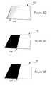
- FIGS. 9 a through 9 f are depictions of 2 planes intersecting at a known angle (16 degrees for 9 ( a ), 9 ( b ) and 9 ( c ); 0.8 degrees for 9 ( d ), 9 ( e ) and 9 ( f )) rendered using a prior-art fixed-point 16-bit Z-buffer ( 9 ( a ), 9 ( d )), a prior art floating-point 16-bit 1/W buffer with 4 bits of exponent ( 9 ( b ), 9 ( e )) and a complementary floating-point 16-bit Z-buffer with 4 bits of exponent ( 9 ( c ), 9 ( f )).
- FIG. 10 is a chart displaying average depth error as a function of the far-to-near distance ratio, for a complementary floating-point 16-bit Z-buffer in accordance with the present invention.
- FIG. 11 is a chart displaying average depth error as a function of the far-to-near distance ratio, for a complementary floating-point 16-bit Z-buffer with different numbers of bits of exponent and mantissa.
- FIG. 12 is a chart displaying average depth error as a function of the far-to-near distance ratio, for a floating-point 16-bit inverse W-buffer with different numbers of bits of exponent and mantissa.
- FIG. 13 is a chart comparing the average depth errors as a function of the far-to-near distance ratio, for the following 16-bit buffers: a prior art Z-buffer, a prior art W-buffer, a prior art inverse W-buffer, and a complementary Z-buffer.
- FIG. 14 is a chart comparing the average depth errors as a function of the far-to-near distance ratio, for the following 24-bit buffers: a prior art Z-buffer, a prior art W-buffer, a prior art inverse W-buffer, and a complementary Z-buffer.
- FIG. 15 is a chart comparing the average depth errors as a function of the far-to-near distance ratio, for the following 32-bit buffers: a prior art Z-buffer, a prior art W-buffer, a prior art inverse W-buffer, and a complementary Z-buffer.
- FIG. 16 is a schematic diagram of a view volume transposed into screen space using a floating-point complementary depth buffer.
- FIG. 17 is a schematic diagram of one embodiment for implementing a complementary depth buffer in a computer system.
- FIG. 1 a the geometry 10 of a scene rendered in 3-dimensional space with a camera positioned at the origin of coordinates, also known as the view space, is schematically shown. Elements of the scene are rendered only if they are located inside of view volume 12 .
- View volume 12 has the shape of a truncated pyramid (or frustum) bounded by six planes: four sides of the pyramid intersect at the common origin of the camera location 14 , and two planes bound the near 16 and far 18 distances from the camera.
- FIG. 1 a shows two side planes of the pyramid projected as solid lines 20 a and 20 b to plane Y-Z, and the two planes 16 and 18 that bound distances from the camera: near plane 16 at distance d and far plane 18 at distance f.
- Depth storage implementations affect the error of the depth buffer storage, which can be defined as the change of the distance in the view space 12 corresponding to the minimal change of the value stored in the depth buffer. The smaller the depth buffer storage error, the better its precision and resolution. Depth buffer error typically changes with distance from the camera; therefore, to compare different depth buffer implementations, one can compare average depth errors for different scene parameters and areas of interest.
- the error of the Zs representation is estimated as the largest of two factors. First, there is a per-vertex error of Zs representation after computation of normalized device coordinates.
- the standard input format for Zs values, as for other per-vertex coordinates, is typically a 32-bit IEEE floating point format.
- Equation [3] represents a mapping of the stored depth values to the normalized range of values in a particular floating-point storage format, from 0 to 1.0. It is one of the possible representations of a floating-point storage format, which may differ, for instance, by the presence or absence of the sign bit or by the particular mapping of the stored depth value to the normalized distance 1.0 in the screen space.
- a single storage value is reserved to represent 1.0
- normalized distance in the screen space corresponding to this storage value according to equation [3] can be mapped to the storage value closest to that reserved to represent 1.0.
- Variations in representation of the single normalized distance by the storage format do not typically change the qualitative relationship between depth errors computed for different depth mapping functions with the same floating-point format.
- the sign bit if present, decreases the total number of bits for mantissa or exponent for the same per-pixel buffer size, but does not typically change the qualitative relationship between depth errors computed for different depth mapping functions with the same floating-point format.
- f is the distance from the camera to the far plane 18 of the view frustum and d is the distance from the camera to the near plane 16 of the view frustum.
- S(Zv) is a number of samples collected at the distance Zv from the camera. Depth error depends on the mapping functions (e.g., equations [4] to [6]) and the maximum of per-vertex (dZs_v) and per-pixel (dZs_p) representation errors:
- Equations [2] through [8] are sufficient to evaluate average normalized depth error for known sampling distribution S(Zv).
- FIGS. 2 and 3 show average depth error as a function of the ratio between distances to the far and near plane for a 16-bit Z-buffer (as defined by equation [4]) for 3 different sampling functions: uniform, increasing from 0 at the near plane (most of the samples are close to far plane), and decreasing to 0 at the far plane (most of the samples are close to the near plane).
- Data for fixed-point storage zero exponent, 16-bit mantissa
- data for floating-point storage (4-bit exponent, 12-bit mantissa) are presented in FIG. 3 .
- the data shows that average depth error in typical prior art Z-buffer methods increases significantly with the increase of the far/near ratio, that it is dependent on the distribution of samples in the 3-dimensional space, and that floating-point storage format decreases average precision.
- FIGS. 4 and 5 show average depth error for a W-buffer (as defined by equation [5]) and the same combinations of sampling distributions and storage formats as in FIGS. 2 and 3.
- FIGS. 6 and 7 show average depth error for an inverse W-buffer (as defined by equation [6]) and the same combinations of sampling distributions and storage formats as for Z and W-buffers.
- mapping function Zv(Zs) is linear because Zs is proportional to Zv (see equation [5]), and the representation function is linear due to fixed-point storage: error does not depend on the stored W value. As a result, error of the distance from the camera to the sampling point remains generally independent from the value of this distance.
- the present invention achieves precision results similar to those produced with a W-buffer—that is, close-to-linear correspondence between Zv and stored depth values—without maintaining linearity for both mapping and representation functions. Instead, the present invention uses non-linear mapping and representation functions that compensate the non-linear behavior of each other, providing nearly linear correspondence between distance from the camera and stored depth.
- each screen depth value Zs described by equation [9] is stored in floating point format, for instance, using representation [3].
- Such compensation is effective enough to make depth error almost independent of the distance to the camera, making it orders of magnitude smaller than for a prior art Z-buffer of the same size (FIG. 8 ).
- FIGS. 9 a through 9 f show a black plane 60 and white plane 62 intersecting at a known angle and rendered using three different types of depth buffers with the same per-pixel storage size of 16 bits.
- the intersection 64 of two planes 60 and 62 should be a straight line for any non-zero angle. Decrease of the intersection angle brings planes closer together, increasing the depth precision required to properly resolve intersection area.
- FIGS. 9 a , 9 b and 9 c depict planes 60 and 62 intersecting at a 16 degree angle.
- Use of prior art fixed-point Z buffer (FIG. 9 a ) shows significant errors due to its lack of precision (see, for example, the jagged pattern at the intersection 64 a ).
- Prior art floating-point 1/W buffer with 4 bits of exponent (FIG. 9 b ) and complementary floating-point Z-buffer with 4 bits of exponent (FIG. 9 c ) show adequate precision to render the intersection region ( 64 b and 64 c ) as a substantially straight line.
- FIGS. 9 d , 9 e and 9 f depict planes 60 and 62 intersecting at a 0.8 degree angle, which roughly corresponds to a 20 ⁇ increase in required depth precision compared with a 16-degree angle.
- prior art fixed-point Z-buffer (FIG. 9 d ) fails to resolve plane intersection, creating a semi-random pattern 64 d instead of a correctly ordered linear intersection.
- Using a prior-art inverse W buffer with 4-bits of exponent (FIG. 9 e ) provides significantly better precision, but still exhibits severe visual artifacts in the intersection area 64 e (jagged pattern).
- Using a complementary floating-point Z-buffer with 4-bits of exponent (FIG. 9f) produces an intersection area 64 f as a substantially ideal straight line, demonstrating significantly better depth precision compared with both prior art solutions.
- FIG. 10 shows average depth error in the 16-bit complementary screen depth Zs (or floating-point Zs) buffer (4 bits exponent, 12 bits mantissa) as a function of the ratio between distances to the far and near planes and three different sampling functions: uniform, increasing from 0 at the near plane (most of the samples are close to far plane), and decreasing to 0 at the far plane (most of the samples are at the near plane).
- Data for fixed-point storage zero exponent, 16-bit mantissa
- FIG. 2 for the fixed-point storage prior art Z-buffer.
- FIG. 11 shows average depth error as a function of the far/near ratio for different sizes of mantissa and exponent in the same 16-bit buffer. The results are shown for a uniform sampling distribution.
- scene parameters may include a known ratio of the distances to the far and near planes and the sampling distribution. Equation [7] can be used to determine average depth error for different sizes of exponent and to select the best exponent size.
- Selection of the exponent size based on known scene parameters can also handle a fixed-point format as a special case with the number of bits of exponent equal to zero or one. As the results of FIG. 11 show, a fixed-point format can be selected for very small far/near ratios or when the area of interest is very close to the near plane.
- exponent size is not confined to the complementary Z-buffer proposed in the present invention and described by equation [9]. While the prior art Z-buffer (equation [4]) and W-buffer (equation [5]) always produce best resolution with fixed-point storage, test results indicate that inverse W-buffer (equation [6]) may benefit from per-frame selection of exponent size.
- FIG. 12 shows results for a 16-bit inverse W-buffer at different sizes of exponent and uniform sampling distribution (e.g., “13.3” denotes 13 bits mantissa and 3 bits exponent).
- FIGS. 13, 14 and 15 compare results for 3 prior art depth buffers and the complementary Z-buffer accordingly to the present invention. In all cases results are produced for uniform sampling distribution. Results for inverse W-buffer and complementary Z-buffer are shown for the exponent sizes specially selected for each far/near ratio, to increase precision in accordance with present invention.
- FIG. 13 shows comparison results for a 16-bit buffer.
- FIG. 14 shows results for a 24-bit buffer.
- FIG. 15 shows results for a 32-bit buffer.
- FIGS. 13 and 14 demonstrate that a complementary Z-buffer, as described in the current invention, typically has better resolution than either the prior art Z-buffer or inverse W-buffer. For 16 bit/pixel and 24 bit/pixel depth buffer sizes, the resolution of a complementary Z-buffer remains up to 2 times lower than for a fixed-point W-buffer. However, a complementary Z-buffer is simpler to implement than a W-buffer and does not require additional per-pixel operations that may decrease overall hardware performance.
- a complementary Z-buffer over a prior art inverse W-buffer can be explained by the fact that a complementary Z-buffer most effectively uses increased resolution of floating-point storage for small storage values by mapping the largest distance from the camera (Zv close to f) to the smallest stored depth values (Zs close to 0).
- An inverse W-buffer mapping is especially ineffective when d/f is close to 1; in this case, most of the range of the stored depth values may remain unused.
- a complementary Z-buffer according to the present invention does not have this disadvantage because it generally maps the range of distances from the camera [d, f] to substantially the full range of stored depth values [0,1].
- FIG. 15 show that at large size of per-pixel depth storage (e.g., 32 bits) a complementary Z-buffer provides the best depth precision in comparison with previous solutions.
- a complementary Z-buffer provides the best depth precision in comparison with previous solutions.
- average depth errors of both the W-buffer and inverse W-buffer become very close, because they are influenced by per-vertex precision of the input (IEEE 32-bit floating-point) rather than storage format precision.
- Precision of the W-buffer is generally optimal with fixed-point storage, but the floating-point input format limits its effective resolution by decreasing the number of mantissa bits in comparison with a fixed point format.
- 32-bit IEEE floating point input format is optimal for current CPUs.
- a complementary Z-buffer provides best depth precision in comparison with prior art solutions, when error of depth representation is limited by the input floating-point format but not by the storage format.
- a complementary Z-buffer in accordance with present invention can be implemented using a variety of possible embodiments.
- a complementary Z value described by equation [9] is computed by modifying a conventional transformation matrix from view to screen space.
- An embodiment that uses a modification of the perspective-projection matrix can generally avoid this loss of precision by using small floating-point values, proportional to d/(f-d), during the computation of complementary Z.
- the resulting Zs values will cover range [ ⁇ 1,0], but the absolute value of the depth will still decrease with an increase of the distance to the camera.
- the sign bit only the absolute value is stored in the depth buffer; the sign can be restored when the depth value is read for visibility test comparisons.
- a depth comparison function used for visibility testing should reverse its testing condition: for instance, instead of determining that “a pixel is visible if new Z is less than or equal to old Z” the function should determine that “a pixel is visible if new Z is greater than or equal to old Z”. Such a change is not required if the depth value is computed as prior_art_Zs ⁇ 1 with the negative sign restored after reading the value from the depth buffer.
- the size of the exponent in the floating-point format used to store the depth value of a given size can be selected for each frame based on known scene parameters. This selection can also be extended to the choice between floating-point format and fixed-point format.
- depth values are always calculated with a large number of exponent and mantissa bits (for instance, depth values can be interpolated using 8 bits of exponent and 28 bits of mantissa) and the calculation result is converted to a value with the number of exponent and mantissa bits selected for storage format (for instance, a floating-point value with 4 bits of exponent and 12 bits of mantissa, or a floating-point value with 5 bits of exponent and 19 bits of mantissa, or a 24-bit integer value).
- depth values can be computed with precision corresponding to selected storage format (for instance, depth values can be interpolated using the same number of bits of exponent as used for the storage of the result as a floating-point value, or depth values can be interpolated as integers if the result is stored as an integer value).
- a complementary Z-buffer generally produces better results than prior art Z-buffer or inverse W-buffer implementations, it may be beneficial to allow an application to use a variety depth buffer methods for compatibility reasons. Therefore, a complementary Z-buffer might be enabled or disabled based on a control signal coming from an application or from an end user. Enabling or disabling of complementary Z-buffer can be accomplished in multiple ways, depending upon implementation.
- the matrix can be reversed to the values used for, e.g., a prior art Z-buffer; if implemented with a per-vertex 1 ⁇ prior_art_Zs computation, the module can be bypassed; if using Z bias to compute prior_art_Zs ⁇ 1 and ignoring the sign, disabling of the complementary Z-buffer can be accomplished by returning Z bias to the prior art value.
- FIG. 17 shows a block-diagram of one possible computer system 100 for rendering three-dimensional objects onto a display 130 , using depth evaluations and visibility testing in accordance with the present invention.
- Several optional blocks are also shown in dotted line (blocks 114 and 120 ) that can be included to perform calculations for certain alternative embodiments of the invention.
- One or more input devices 102 receive information regarding objects within a computer graphics scene. These devices can include, among other things, keyboards, computer mice, tablets, and the like, for use by a computer programmer in devising a scene, or joysticks and the like by a user operating a computer graphics program, such as a game.
- a per-object processing module 106 performs high-level processing of each object in the scene, based upon its inputted characteristics. Per-object processing module 106 then provides one or more transformation matrices 108 that provide complete information about transforming the local coordinate information of each object into the common coordinate system of the screen space, given a particular camera angle, field of view, and other parameters.
- a per-vertex processing module 110 uses the transformation matrices 108 , and the inputted object information to transform each vertex of each polygon constituting the scene objects into final screen coordinates. That information can then be downloaded to a graphics subsystem 112 , provided, for example, in a specialized graphics processing chip set or card attached to the CPU subsystem 104 .
- per-vertex depth converter 114 transforms, e.g., the prior-art depth Z for each vertex provided by per-vertex processing module 110 into a complementary depth, e.g., 1 ⁇ Z (or Z ⁇ 1), for use in the methods of the present invention.
- the complementary depth function can be provided in the transformation matrices 110 themselves, eliminating the need to perform further transformations in the graphics subsystem 112 .
- Polygon setup and rasterizing module 116 takes the polygon information provided by per-vertex processing module, and begins the process of final rasterization, including computing gradients across a polygon, the slopes at edges, and positions of pixels.
- Depth interpolator 118 takes the vertex coordinates of each polygon and interpolates the depth of a pixel based upon the depths of its surrounding vertices. If vertex depths have already been transformed to complementary depth values by a per-vertex depth converter 1 14 , then the interpolated pixel depths produced by depth interpolator 118 will already be complementary depth values.
- a per-pixel depth converter 120 can, at this stage, transform, e.g., an interpolated Z value of a pixel into a complementary interpolated value (e.g., 1 ⁇ Z or Z ⁇ 1). Even if the per-vertex depth values are already transformed into complementary depth values, the per-pixel converter 120 can provide additional functions, such as reversing the sign of depth (e.g., transforming negative Z ⁇ 1 values into positive 1 ⁇ Z complementary depth values). The per-pixel converter 120 can also perform format conversions (from, e.g., a high precision integer or floating-point number (from the depth interpolation process) into the final precision integer or floating-point number that will be compared and stored with the values in the depth storage buffer 124 ).
- format conversions from, e.g., a high precision integer or floating-point number (from the depth interpolation process) into the final precision integer or floating-point number that will be compared and stored with the values in the depth storage buffer 124 ).
- the resulting interpolated complementary depth value for a pixel is then compared by the visibility test and depth storage module 122 with the complementary depth value stored in the depth storage buffer 124 for the same location. Depending upon the convention used for the complementary depth values, if the current complementary depth value is greater than or less than the stored complementary depth value, the pixel is either visible or not.
- the result of the visibility test is provided to the color computation and storage module 126 , which produces final color for each visible pixel using information provided by the polygon setup and rasterizer module, which is then stored in color storage buffer 128 , for display upon display 130 .
- Each module can be implemented as a software program stored on a tangible memory (e.g., random access memory, read only memory, CD-ROM memory, hard disk drive) to be read by a central processing unit to implement the functions of the present invention.
- the modules can comprise programming instructions transmitted to a general purpose computer or to graphics processing hardware via a transmission carrier wave.
- the modules can be implemented as hardware logic circuitry implementing the functions encompassed by the present invention.
Landscapes
- Physics & Mathematics (AREA)
- Engineering & Computer Science (AREA)
- Geometry (AREA)
- Computer Graphics (AREA)
- General Physics & Mathematics (AREA)
- Theoretical Computer Science (AREA)
- Image Generation (AREA)
Abstract
Description


Claims (8)
Priority Applications (1)
| Application Number | Priority Date | Filing Date | Title |
|---|---|---|---|
| US09/778,355 US6453065B1 (en) | 1999-08-02 | 2001-02-06 | Floating-point complementary depth buffer |
Applications Claiming Priority (2)
| Application Number | Priority Date | Filing Date | Title |
|---|---|---|---|
| US09/365,685 US6285779B1 (en) | 1999-08-02 | 1999-08-02 | Floating-point complementary depth buffer |
| US09/778,355 US6453065B1 (en) | 1999-08-02 | 2001-02-06 | Floating-point complementary depth buffer |
Related Parent Applications (1)
| Application Number | Title | Priority Date | Filing Date |
|---|---|---|---|
| US09/365,685 Division US6285779B1 (en) | 1999-08-02 | 1999-08-02 | Floating-point complementary depth buffer |
Publications (1)
| Publication Number | Publication Date |
|---|---|
| US6453065B1 true US6453065B1 (en) | 2002-09-17 |
Family
ID=23439908
Family Applications (2)
| Application Number | Title | Priority Date | Filing Date |
|---|---|---|---|
| US09/365,685 Expired - Fee Related US6285779B1 (en) | 1999-08-02 | 1999-08-02 | Floating-point complementary depth buffer |
| US09/778,355 Expired - Fee Related US6453065B1 (en) | 1999-08-02 | 2001-02-06 | Floating-point complementary depth buffer |
Family Applications Before (1)
| Application Number | Title | Priority Date | Filing Date |
|---|---|---|---|
| US09/365,685 Expired - Fee Related US6285779B1 (en) | 1999-08-02 | 1999-08-02 | Floating-point complementary depth buffer |
Country Status (3)
| Country | Link |
|---|---|
| US (2) | US6285779B1 (en) |
| AU (1) | AU6398900A (en) |
| WO (1) | WO2001009761A1 (en) |
Cited By (6)
| Publication number | Priority date | Publication date | Assignee | Title |
|---|---|---|---|---|
| US6724394B1 (en) * | 2000-05-31 | 2004-04-20 | Nvidia Corporation | Programmable pixel shading architecture |
| US20070040832A1 (en) * | 2003-07-31 | 2007-02-22 | Tan Tiow S | Trapezoidal shadow maps |
| US20070216710A1 (en) * | 2006-03-15 | 2007-09-20 | Microsoft Corporation | Automatically generating appropriate near and far clipping planes for a 3D scene while guaranteeing minimum of Z-buffer precision |
| US20080089607A1 (en) * | 2006-10-11 | 2008-04-17 | Kazuhiro Hirade | Semiconductor integrated circuit device and rendering processing display system |
| US20090322746A1 (en) * | 2008-06-27 | 2009-12-31 | Microsoft Corporation | Rational z-buffer for decreasing a likelihood of z-buffer collisions |
| US8914801B2 (en) * | 2010-05-27 | 2014-12-16 | International Business Machine Corporation | Hardware instructions to accelerate table-driven mathematical computation of reciprocal square, cube, forth root and their reciprocal functions, and the evaluation of exponential and logarithmic families of functions |
Families Citing this family (43)
| Publication number | Priority date | Publication date | Assignee | Title |
|---|---|---|---|---|
| US6727900B1 (en) * | 1998-09-07 | 2004-04-27 | Renesas Technology Corp. | Semiconductor integrated circuit device |
| US6732259B1 (en) | 1999-07-30 | 2004-05-04 | Mips Technologies, Inc. | Processor having a conditional branch extension of an instruction set architecture |
| US7242414B1 (en) * | 1999-07-30 | 2007-07-10 | Mips Technologies, Inc. | Processor having a compare extension of an instruction set architecture |
| US7346643B1 (en) | 1999-07-30 | 2008-03-18 | Mips Technologies, Inc. | Processor with improved accuracy for multiply-add operations |
| US6912559B1 (en) | 1999-07-30 | 2005-06-28 | Mips Technologies, Inc. | System and method for improving the accuracy of reciprocal square root operations performed by a floating-point unit |
| US6697832B1 (en) | 1999-07-30 | 2004-02-24 | Mips Technologies, Inc. | Floating-point processor with improved intermediate result handling |
| US6631392B1 (en) | 1999-07-30 | 2003-10-07 | Mips Technologies, Inc. | Method and apparatus for predicting floating-point exceptions |
| US6714197B1 (en) | 1999-07-30 | 2004-03-30 | Mips Technologies, Inc. | Processor having an arithmetic extension of an instruction set architecture |
| US6618048B1 (en) * | 1999-10-28 | 2003-09-09 | Nintendo Co., Ltd. | 3D graphics rendering system for performing Z value clamping in near-Z range to maximize scene resolution of visually important Z components |
| US6717577B1 (en) | 1999-10-28 | 2004-04-06 | Nintendo Co., Ltd. | Vertex cache for 3D computer graphics |
| US6476813B1 (en) | 1999-11-30 | 2002-11-05 | Silicon Graphics, Inc. | Method and apparatus for preparing a perspective view of an approximately spherical surface portion |
| US6650325B1 (en) * | 1999-12-06 | 2003-11-18 | Nvidia Corporation | Method, apparatus and article of manufacture for boustrophedonic rasterization |
| US6628281B1 (en) * | 2000-02-24 | 2003-09-30 | International Business Machines Corporation | Method and system for computing the intersection of a bounding volume and screen-aligned plane |
| US6996596B1 (en) | 2000-05-23 | 2006-02-07 | Mips Technologies, Inc. | Floating-point processor with operating mode having improved accuracy and high performance |
| US6670958B1 (en) * | 2000-05-26 | 2003-12-30 | Ati International, Srl | Method and apparatus for routing data to multiple graphics devices |
| GB2364234A (en) * | 2000-07-04 | 2002-01-23 | D D S A Internat Ltd | Child's garment |
| US7196710B1 (en) | 2000-08-23 | 2007-03-27 | Nintendo Co., Ltd. | Method and apparatus for buffering graphics data in a graphics system |
| US7538772B1 (en) | 2000-08-23 | 2009-05-26 | Nintendo Co., Ltd. | Graphics processing system with enhanced memory controller |
| US6700586B1 (en) | 2000-08-23 | 2004-03-02 | Nintendo Co., Ltd. | Low cost graphics with stitching processing hardware support for skeletal animation |
| US6636214B1 (en) | 2000-08-23 | 2003-10-21 | Nintendo Co., Ltd. | Method and apparatus for dynamically reconfiguring the order of hidden surface processing based on rendering mode |
| US6811489B1 (en) | 2000-08-23 | 2004-11-02 | Nintendo Co., Ltd. | Controller interface for a graphics system |
| US7576748B2 (en) | 2000-11-28 | 2009-08-18 | Nintendo Co. Ltd. | Graphics system with embedded frame butter having reconfigurable pixel formats |
| US6707458B1 (en) | 2000-08-23 | 2004-03-16 | Nintendo Co., Ltd. | Method and apparatus for texture tiling in a graphics system |
| US20030063087A1 (en) * | 2001-09-28 | 2003-04-03 | Doyle Peter L. | Variable-formatable width buffer and method of use |
| KR100446635B1 (en) * | 2001-11-27 | 2004-09-04 | 삼성전자주식회사 | Apparatus and method for depth image-based representation of 3-dimensional object |
| US6982713B2 (en) * | 2003-01-13 | 2006-01-03 | Xgi Technology Inc. | System and method for clearing depth and color buffers in a real-time graphics rendering system |
| US7403201B2 (en) * | 2003-01-20 | 2008-07-22 | Sanyo Electric Co., Ltd. | Three-dimensional video providing method and three-dimensional video display device |
| US7139005B2 (en) * | 2003-09-13 | 2006-11-21 | Microsoft Corporation | Optimized fixed-point mathematical library and graphics functions for a software-implemented graphics rendering system and method using a normalized homogenous coordinate system |
| US7593010B2 (en) * | 2003-09-18 | 2009-09-22 | Microsoft Corporation | Software-implemented transform and lighting module and pipeline for graphics rendering on embedded platforms using a fixed-point normalized homogenous coordinate system |
| US8744198B1 (en) * | 2007-11-20 | 2014-06-03 | Lucasfilm Entertainment Company Ltd. | Image compression and decompression |
| US9294751B2 (en) | 2009-09-09 | 2016-03-22 | Mattel, Inc. | Method and system for disparity adjustment during stereoscopic zoom |
| US9426441B2 (en) | 2010-03-08 | 2016-08-23 | Dolby Laboratories Licensing Corporation | Methods for carrying and transmitting 3D z-norm attributes in digital TV closed captioning |
| TWI420413B (en) * | 2010-07-15 | 2013-12-21 | Chunghwa Picture Tubes Ltd | Depth map enhancing method and computer-readable medium therefor |
| US20130010077A1 (en) * | 2011-01-27 | 2013-01-10 | Khang Nguyen | Three-dimensional image capturing apparatus and three-dimensional image capturing method |
| US9519994B2 (en) * | 2011-04-15 | 2016-12-13 | Dolby Laboratories Licensing Corporation | Systems and methods for rendering 3D image independent of display size and viewing distance |
| US9336240B2 (en) * | 2011-07-15 | 2016-05-10 | Apple Inc. | Geo-tagging digital images |
| US9747519B2 (en) * | 2015-04-24 | 2017-08-29 | Microsoft Technology Licensing, Llc | Classifying ambiguous image data |
| US11170294B2 (en) * | 2016-01-07 | 2021-11-09 | Intel Corporation | Hardware accelerated machine learning |
| US10102668B2 (en) * | 2016-05-05 | 2018-10-16 | Nvidia Corporation | System, method, and computer program product for rendering at variable sampling rates using projective geometric distortion |
| US11120329B2 (en) | 2016-05-07 | 2021-09-14 | Intel Corporation | Multicast network and memory transfer optimizations for neural network hardware acceleration |
| US10817802B2 (en) | 2016-05-07 | 2020-10-27 | Intel Corporation | Apparatus for hardware accelerated machine learning |
| CN109685885B (en) * | 2017-10-18 | 2023-05-23 | 上海质尊电子科技有限公司 | Rapid method for converting 3D image by using depth map |
| MX2020007663A (en) | 2018-01-19 | 2020-09-14 | Interdigital Vc Holdings Inc | Processing a point cloud. |
Citations (9)
| Publication number | Priority date | Publication date | Assignee | Title |
|---|---|---|---|---|
| US5301263A (en) * | 1990-09-18 | 1994-04-05 | Hewlett-Packard Company | High memory bandwidth system for updating z-buffer values |
| US5359704A (en) * | 1991-10-30 | 1994-10-25 | International Business Machines Corporation | Method for selecting silhouette and visible edges in wire frame images in a computer graphics display system |
| US5542032A (en) * | 1993-10-04 | 1996-07-30 | Loral Federal Systems Company | Fast display of images of three-dimensional surfaces without aliasing |
| US5748863A (en) * | 1995-10-06 | 1998-05-05 | International Business Machines Corporation | Method and system for fast interpolation of depth buffer values in a computer graphics display system |
| US5808618A (en) * | 1994-10-21 | 1998-09-15 | Matsushita Electric Industrial Co., Ltd. | Three-dimensional displaying apparatus having frame buffer and depth buffer |
| US5819017A (en) * | 1995-08-22 | 1998-10-06 | Silicon Graphics, Inc. | Apparatus and method for selectively storing depth information of a 3-D image |
| US5856829A (en) * | 1995-05-10 | 1999-01-05 | Cagent Technologies, Inc. | Inverse Z-buffer and video display system having list-based control mechanism for time-deferred instructing of 3D rendering engine that also responds to supervisory immediate commands |
| US6046746A (en) * | 1996-07-01 | 2000-04-04 | Sun Microsystems, Inc. | Method and apparatus implementing high resolution rendition of Z-buffered primitives |
| US6115047A (en) * | 1996-07-01 | 2000-09-05 | Sun Microsystems, Inc. | Method and apparatus for implementing efficient floating point Z-buffering |
-
1999
- 1999-08-02 US US09/365,685 patent/US6285779B1/en not_active Expired - Fee Related
-
2000
- 2000-08-02 AU AU63989/00A patent/AU6398900A/en not_active Abandoned
- 2000-08-02 WO PCT/US2000/021233 patent/WO2001009761A1/en active Application Filing
-
2001
- 2001-02-06 US US09/778,355 patent/US6453065B1/en not_active Expired - Fee Related
Patent Citations (9)
| Publication number | Priority date | Publication date | Assignee | Title |
|---|---|---|---|---|
| US5301263A (en) * | 1990-09-18 | 1994-04-05 | Hewlett-Packard Company | High memory bandwidth system for updating z-buffer values |
| US5359704A (en) * | 1991-10-30 | 1994-10-25 | International Business Machines Corporation | Method for selecting silhouette and visible edges in wire frame images in a computer graphics display system |
| US5542032A (en) * | 1993-10-04 | 1996-07-30 | Loral Federal Systems Company | Fast display of images of three-dimensional surfaces without aliasing |
| US5808618A (en) * | 1994-10-21 | 1998-09-15 | Matsushita Electric Industrial Co., Ltd. | Three-dimensional displaying apparatus having frame buffer and depth buffer |
| US5856829A (en) * | 1995-05-10 | 1999-01-05 | Cagent Technologies, Inc. | Inverse Z-buffer and video display system having list-based control mechanism for time-deferred instructing of 3D rendering engine that also responds to supervisory immediate commands |
| US5819017A (en) * | 1995-08-22 | 1998-10-06 | Silicon Graphics, Inc. | Apparatus and method for selectively storing depth information of a 3-D image |
| US5748863A (en) * | 1995-10-06 | 1998-05-05 | International Business Machines Corporation | Method and system for fast interpolation of depth buffer values in a computer graphics display system |
| US6046746A (en) * | 1996-07-01 | 2000-04-04 | Sun Microsystems, Inc. | Method and apparatus implementing high resolution rendition of Z-buffered primitives |
| US6115047A (en) * | 1996-07-01 | 2000-09-05 | Sun Microsystems, Inc. | Method and apparatus for implementing efficient floating point Z-buffering |
Cited By (9)
| Publication number | Priority date | Publication date | Assignee | Title |
|---|---|---|---|---|
| US6724394B1 (en) * | 2000-05-31 | 2004-04-20 | Nvidia Corporation | Programmable pixel shading architecture |
| US20070040832A1 (en) * | 2003-07-31 | 2007-02-22 | Tan Tiow S | Trapezoidal shadow maps |
| US20070216710A1 (en) * | 2006-03-15 | 2007-09-20 | Microsoft Corporation | Automatically generating appropriate near and far clipping planes for a 3D scene while guaranteeing minimum of Z-buffer precision |
| US7525542B2 (en) * | 2006-03-15 | 2009-04-28 | Microsoft Corporation | Automatically generating appropriate near and far clipping planes for a 3D scene while guaranteeing minimum of Z-buffer precision |
| US20080089607A1 (en) * | 2006-10-11 | 2008-04-17 | Kazuhiro Hirade | Semiconductor integrated circuit device and rendering processing display system |
| US7953292B2 (en) * | 2006-10-11 | 2011-05-31 | Renesas Electronics Corporation | Semiconductor integrated circuit device and rendering processing display system |
| US20090322746A1 (en) * | 2008-06-27 | 2009-12-31 | Microsoft Corporation | Rational z-buffer for decreasing a likelihood of z-buffer collisions |
| US8154546B2 (en) * | 2008-06-27 | 2012-04-10 | Microsoft Corporation | Rational Z-buffer for decreasing a likelihood of Z-buffer collisions |
| US8914801B2 (en) * | 2010-05-27 | 2014-12-16 | International Business Machine Corporation | Hardware instructions to accelerate table-driven mathematical computation of reciprocal square, cube, forth root and their reciprocal functions, and the evaluation of exponential and logarithmic families of functions |
Also Published As
| Publication number | Publication date |
|---|---|
| US6285779B1 (en) | 2001-09-04 |
| AU6398900A (en) | 2001-02-19 |
| WO2001009761A1 (en) | 2001-02-08 |
Similar Documents
| Publication | Publication Date | Title |
|---|---|---|
| US6453065B1 (en) | Floating-point complementary depth buffer | |
| US5704024A (en) | Method and an apparatus for generating reflection vectors which can be unnormalized and for using these reflection vectors to index locations on an environment map | |
| US7116337B2 (en) | Transparent depth sorting | |
| EP0622747B1 (en) | Method and apparatus for an adaptive texture mapping controller | |
| US6677945B2 (en) | Multi-resolution depth buffer | |
| US7432936B2 (en) | Texture data anti-aliasing method and apparatus | |
| US9208605B1 (en) | Temporal antialiasing in a multisampling graphics pipeline | |
| US7292242B1 (en) | Clipping with addition of vertices to existing primitives | |
| US6292192B1 (en) | System and method for the direct rendering of curve bounded objects | |
| Ewins et al. | Mip-map level selection for texture mapping | |
| US6437781B1 (en) | Computer graphics system having per pixel fog blending | |
| JPH0778267A (en) | Method for display of shadow and computer-controlled display system | |
| US7903121B2 (en) | System and method for image-based rendering with object proxies | |
| US5841443A (en) | Method for triangle subdivision in computer graphics texture mapping to eliminate artifacts in high perspective polygons | |
| US7158133B2 (en) | System and method for shadow rendering | |
| US5977983A (en) | Method and apparatus for adjusting graphics processing procedures based on a selectable speed/quality gauge | |
| JPH07101462B2 (en) | Display method and device in computer graphics system | |
| Wang et al. | Second-depth shadow mapping | |
| Darsa et al. | Walkthroughs of complex environments using image-based simplification | |
| US6756989B1 (en) | Method, system, and computer program product for filtering a texture applied to a surface of a computer generated object | |
| JP3349871B2 (en) | Image processing device | |
| US20080012852A1 (en) | Volume rendering processing distribution in a graphics processing unit | |
| US5748863A (en) | Method and system for fast interpolation of depth buffer values in a computer graphics display system | |
| US20030184546A1 (en) | Image processing method | |
| US5926183A (en) | Efficient rendering utilizing user defined rooms and windows |
Legal Events
| Date | Code | Title | Description |
|---|---|---|---|
| AS | Assignment |
Owner name: TRIDENT MICROSYSTEMS, INC., CALIFORNIA Free format text: ASSIGNMENT OF ASSIGNORS INTEREST;ASSIGNORS:LAPIDOUS, EUGENE;JIAO, GUOFANG;REEL/FRAME:011542/0469 Effective date: 19990802 |
|
| AS | Assignment |
Owner name: XGI TECHNOLOGY INC., CAYMAN ISLANDS Free format text: ASSIGNMENT OF ASSIGNORS INTEREST;ASSIGNOR:TRIDENT MICROSYSTEMS, INC.;REEL/FRAME:015582/0376 Effective date: 20040621 |
|
| REMI | Maintenance fee reminder mailed | ||
| REIN | Reinstatement after maintenance fee payment confirmed | ||
| FP | Lapsed due to failure to pay maintenance fee |
Effective date: 20060917 |
|
| FEPP | Fee payment procedure |
Free format text: PETITION RELATED TO MAINTENANCE FEES FILED (ORIGINAL EVENT CODE: PMFP); ENTITY STATUS OF PATENT OWNER: LARGE ENTITY Free format text: PETITION RELATED TO MAINTENANCE FEES GRANTED (ORIGINAL EVENT CODE: PMFG); ENTITY STATUS OF PATENT OWNER: LARGE ENTITY Free format text: PAT HOLDER CLAIMS SMALL ENTITY STATUS, ENTITY STATUS SET TO SMALL (ORIGINAL EVENT CODE: LTOS); ENTITY STATUS OF PATENT OWNER: LARGE ENTITY |
|
| FEPP | Fee payment procedure |
Free format text: PAYER NUMBER DE-ASSIGNED (ORIGINAL EVENT CODE: RMPN); ENTITY STATUS OF PATENT OWNER: LARGE ENTITY Free format text: PAYOR NUMBER ASSIGNED (ORIGINAL EVENT CODE: ASPN); ENTITY STATUS OF PATENT OWNER: LARGE ENTITY |
|
| PRDP | Patent reinstated due to the acceptance of a late maintenance fee |
Effective date: 20080307 |
|
| FPAY | Fee payment |
Year of fee payment: 4 |
|
| SULP | Surcharge for late payment | ||
| FPAY | Fee payment |
Year of fee payment: 8 |
|
| FEPP | Fee payment procedure |
Free format text: PAT HOLDER NO LONGER CLAIMS SMALL ENTITY STATUS, ENTITY STATUS SET TO UNDISCOUNTED (ORIGINAL EVENT CODE: STOL); ENTITY STATUS OF PATENT OWNER: LARGE ENTITY |
|
| AS | Assignment |
Owner name: SILICON INTEGRATED SYSTEMS CORP., TAIWAN Free format text: MERGER;ASSIGNOR:XGI TECHNOLOGY INC.;REEL/FRAME:027358/0078 Effective date: 20101111 |
|
| FEPP | Fee payment procedure |
Free format text: PAYER NUMBER DE-ASSIGNED (ORIGINAL EVENT CODE: RMPN); ENTITY STATUS OF PATENT OWNER: LARGE ENTITY Free format text: PAYOR NUMBER ASSIGNED (ORIGINAL EVENT CODE: ASPN); ENTITY STATUS OF PATENT OWNER: LARGE ENTITY |
|
| REMI | Maintenance fee reminder mailed | ||
| LAPS | Lapse for failure to pay maintenance fees | ||
| STCH | Information on status: patent discontinuation |
Free format text: PATENT EXPIRED DUE TO NONPAYMENT OF MAINTENANCE FEES UNDER 37 CFR 1.362 |
|
| FP | Lapsed due to failure to pay maintenance fee |
Effective date: 20140917 |