US6452735B1 - Disk drive that monitors the flying height of a dual element transducer using a thermally induced signal during write operations - Google Patents
Disk drive that monitors the flying height of a dual element transducer using a thermally induced signal during write operations Download PDFInfo
- Publication number
- US6452735B1 US6452735B1 US09/357,094 US35709499A US6452735B1 US 6452735 B1 US6452735 B1 US 6452735B1 US 35709499 A US35709499 A US 35709499A US 6452735 B1 US6452735 B1 US 6452735B1
- Authority
- US
- United States
- Prior art keywords
- write
- signal
- disk drive
- induced signal
- read
- Prior art date
- Legal status (The legal status is an assumption and is not a legal conclusion. Google has not performed a legal analysis and makes no representation as to the accuracy of the status listed.)
- Expired - Lifetime
Links
Images


Classifications
-
- G—PHYSICS
- G11—INFORMATION STORAGE
- G11B—INFORMATION STORAGE BASED ON RELATIVE MOVEMENT BETWEEN RECORD CARRIER AND TRANSDUCER
- G11B27/00—Editing; Indexing; Addressing; Timing or synchronising; Monitoring; Measuring tape travel
- G11B27/36—Monitoring, i.e. supervising the progress of recording or reproducing
-
- G—PHYSICS
- G11—INFORMATION STORAGE
- G11B—INFORMATION STORAGE BASED ON RELATIVE MOVEMENT BETWEEN RECORD CARRIER AND TRANSDUCER
- G11B21/00—Head arrangements not specific to the method of recording or reproducing
- G11B21/16—Supporting the heads; Supporting the sockets for plug-in heads
- G11B21/20—Supporting the heads; Supporting the sockets for plug-in heads while the head is in operative position but stationary or permitting minor movements to follow irregularities in surface of record carrier
- G11B21/21—Supporting the heads; Supporting the sockets for plug-in heads while the head is in operative position but stationary or permitting minor movements to follow irregularities in surface of record carrier with provision for maintaining desired spacing of head from record carrier, e.g. fluid-dynamic spacing, slider
-
- G—PHYSICS
- G11—INFORMATION STORAGE
- G11B—INFORMATION STORAGE BASED ON RELATIVE MOVEMENT BETWEEN RECORD CARRIER AND TRANSDUCER
- G11B5/00—Recording by magnetisation or demagnetisation of a record carrier; Reproducing by magnetic means; Record carriers therefor
- G11B5/127—Structure or manufacture of heads, e.g. inductive
- G11B5/33—Structure or manufacture of flux-sensitive heads, i.e. for reproduction only; Combination of such heads with means for recording or erasing only
- G11B5/39—Structure or manufacture of flux-sensitive heads, i.e. for reproduction only; Combination of such heads with means for recording or erasing only using magneto-resistive devices or effects
- G11B5/3903—Structure or manufacture of flux-sensitive heads, i.e. for reproduction only; Combination of such heads with means for recording or erasing only using magneto-resistive devices or effects using magnetic thin film layers or their effects, the films being part of integrated structures
- G11B5/3906—Details related to the use of magnetic thin film layers or to their effects
- G11B5/3945—Heads comprising more than one sensitive element
- G11B5/3948—Heads comprising more than one sensitive element the sensitive elements being active read-out elements
-
- G—PHYSICS
- G11—INFORMATION STORAGE
- G11B—INFORMATION STORAGE BASED ON RELATIVE MOVEMENT BETWEEN RECORD CARRIER AND TRANSDUCER
- G11B5/00—Recording by magnetisation or demagnetisation of a record carrier; Reproducing by magnetic means; Record carriers therefor
- G11B5/48—Disposition or mounting of heads or head supports relative to record carriers ; arrangements of heads, e.g. for scanning the record carrier to increase the relative speed
- G11B5/58—Disposition or mounting of heads or head supports relative to record carriers ; arrangements of heads, e.g. for scanning the record carrier to increase the relative speed with provision for moving the head for the purpose of maintaining alignment of the head relative to the record carrier during transducing operation, e.g. to compensate for surface irregularities of the latter or for track following
- G11B5/60—Fluid-dynamic spacing of heads from record-carriers
- G11B5/6005—Specially adapted for spacing from a rotating disc using a fluid cushion
- G11B5/6011—Control of flying height
- G11B5/6029—Measurement using values derived from the data signal read from the disk
-
- G—PHYSICS
- G11—INFORMATION STORAGE
- G11B—INFORMATION STORAGE BASED ON RELATIVE MOVEMENT BETWEEN RECORD CARRIER AND TRANSDUCER
- G11B5/00—Recording by magnetisation or demagnetisation of a record carrier; Reproducing by magnetic means; Record carriers therefor
- G11B5/48—Disposition or mounting of heads or head supports relative to record carriers ; arrangements of heads, e.g. for scanning the record carrier to increase the relative speed
- G11B5/58—Disposition or mounting of heads or head supports relative to record carriers ; arrangements of heads, e.g. for scanning the record carrier to increase the relative speed with provision for moving the head for the purpose of maintaining alignment of the head relative to the record carrier during transducing operation, e.g. to compensate for surface irregularities of the latter or for track following
- G11B5/60—Fluid-dynamic spacing of heads from record-carriers
- G11B5/6005—Specially adapted for spacing from a rotating disc using a fluid cushion
- G11B5/6011—Control of flying height
- G11B5/6076—Detecting head-disk contact
-
- G—PHYSICS
- G11—INFORMATION STORAGE
- G11B—INFORMATION STORAGE BASED ON RELATIVE MOVEMENT BETWEEN RECORD CARRIER AND TRANSDUCER
- G11B5/00—Recording by magnetisation or demagnetisation of a record carrier; Reproducing by magnetic means; Record carriers therefor
- G11B2005/0002—Special dispositions or recording techniques
- G11B2005/0005—Arrangements, methods or circuits
- G11B2005/001—Controlling recording characteristics of record carriers or transducing characteristics of transducers by means not being part of their structure
- G11B2005/0013—Controlling recording characteristics of record carriers or transducing characteristics of transducers by means not being part of their structure of transducers, e.g. linearisation, equalisation
- G11B2005/0016—Controlling recording characteristics of record carriers or transducing characteristics of transducers by means not being part of their structure of transducers, e.g. linearisation, equalisation of magnetoresistive transducers
-
- G—PHYSICS
- G11—INFORMATION STORAGE
- G11B—INFORMATION STORAGE BASED ON RELATIVE MOVEMENT BETWEEN RECORD CARRIER AND TRANSDUCER
- G11B2220/00—Record carriers by type
- G11B2220/20—Disc-shaped record carriers
Definitions
- the present invention relates to digital storage devices and, more particularly, to disk drives which monitor the flying height of dual element transducers that employ magneto-resistive (MR) read elements.
- MR magneto-resistive
- a disk drive is a digital data storage device that stores information within concentric tracks on a storage disk.
- the storage disk is coated on both of its primary surfaces with a magnetic material that is capable of changing its magnetic orientation in response to an applied magnetic field.
- the disk is rotated about a central axis at a constant rate.
- a magnetic transducer or head is positioned above (or below) a desired track of the disk while the disk is spinning.
- Writing is performed by delivering a polarity-switching write current signal to the transducer while the transducer is positioned above (or below) the desired track.
- the write signal creates a variable magnetic field at a gap portion of the transducer that induces magnetically polarized transitions into the desired track.
- the magnetically polarized transitions are representative of the data being stored.
- Reading is performed by sensing the magnetically polarized transitions on a track with the transducer. As the disk spins below (or above) the transducer, the magnetically polarized transitions on the track induce a varying magnetic field into the transducer.
- the transducer converts the varying magnetic field into an analog read signal that is delivered to a preamplifier and then to a read channel for appropriate processing.
- the read channel converts the analog read signal into a digital signal that is processed and then provided by a controller to a host computer system.
- FIG. 1 illustrates a standard disk drive, generally designated 10 .
- the disk drive 10 includes a disk 12 that is rotated by a spin motor 14 .
- the spin motor 14 is mounted to a base plate 16 .
- An actuator arm assembly 18 is also mounted to the base plate 16 .
- the actuator arm assembly 18 includes a transducer 20 mounted to a flexure arm 22 , which is attached to an actuator arm 24 that can rotate about a bearing assembly 26 .
- the actuator arm assembly 18 includes a voice coil motor (VCM) 28 , which radially positions the transducer 20 relative to the disk 12 .
- VCM voice coil motor
- the spin motor 14 , transducer 20 and VCM 28 are coupled to electronic circuits 30 mounted to a printed circuit board 32 .
- the electronic circuits 30 typically include a preamplifier, a read channel, a servo control unit, a microprocessor-based controller and a random access memory (RAM).
- the disk drive 10 may include a plurality of disks 12 , each with two recording surfaces.
- two actuator arm assemblies 18 are provided for each disk 12 .
- the transducer 20 is a dual element transducer that includes separate read and write elements.
- Single element transducers usually contain a single inductive element that performs both read and write functions, whereas dual element transducers usually contain a magneto-resistive (MR) read element and an inductive write element.
- the MR read element can be a conventional magneto-resistive element, a giant magneto-resistive (GMR) element, or a similar component.
- the read and write elements can be optimized for their respective functions. For example, MR read elements are more sensitive than inductive read elements to small variable magnetic fields, which permits MR read elements to read much fainter signals from the disk surface. Employing an MR read element permits data to be more densely packed on the disk surface.
- MR read elements generally include a strip of magneto-resistive material between two magnetic shields. When properly biased, the resistance of the magneto-resistive material varies almost linearly with an applied magnetic field.
- the MR strip is positioned above (or below) a desired track within the varying magnetic field caused by magnetic transitions on the track and a constant bias current is passed through the strip.
- the variable voltage provides an analog read signal which is then amplified by the preamplifier, processed and converted into digital form by the read channel, and transferred by the controller to a host computer.
- FIG. 2 is a diagrammatic representation of an air bearing surface of the transducer 20 which faces the disk 12 .
- the transducer 20 includes an inductive write element 34 , a write gap 36 , a first shield 38 , a second shield 40 , a read gap 42 , and an MR read element 44 .
- the magnetically polarized transitions previously written onto the disk 12 are read by the MR read element 44 .
- the first and second shields 38 and 40 form the read gap 42 which serves to focus the flux from the magnetically polarized transitions onto the MR read element 44 by shielding the MR element 44 from other sources of magnetic flux (e.g., sources of magnetic flux not associated with the particular location from which information is being read).
- the first and second shields 38 and 40 shunt extraneous magnetic flux away from the MR read element 44 as reading occurs.
- variable current is applied to write coils (not shown) in the transducer 20 which induce magnetic flux across the write gap 36 between the write element 34 and the first shield 38 .
- the write element 34 and first shield 38 act as poles for an electromagnet which induces the magnetic flux across the write gap 36 that records magnetically polarized transitions on the disk 12 .
- the magnetic flux in the write gap 36 has relatively high intensity, and the MR read element 44 is in close proximity to the write gap 36 , a large amount of the magnetic flux across the write gap 36 strikes the MR read element 44 during a write operation. Consequently, the MR read element 44 is typically not used to read data from the disk 12 during a write operation.
- FIG. 3 is a simplified diagrammatic representation of a cross-sectional view of an air bearing slider 46 that includes the transducer 20 flying above a disk surface 48 of the disk 12 .
- the slider 46 is located at the distal end (opposite VCM 28 ) of the actuator arm assembly 18 .
- the slider 46 includes a leading edge 50 and a trailing edge 52 .
- the transducer 20 is located proximate the trailing edge 52 .
- the disk 12 is rotated in the direction of arrow A from the leading edge 50 to the trailing edge 52 .
- the slider 46 is aerodynamically designed so that when the disk 12 revolves at its normal operating speed, a small cushion of air between the slider 46 and the disk surface 48 lifts the slider 46 (and hence the transducer 20 ) a predetermined distance above the disk surface 48 .
- the distance between the transducer 20 and the disk surface 48 is known as the flying height (h f ) of the transducer 20 .
- the performance of the disk drive 10 will depend, to a large extent, on whether the flying height of the transducer 20 stays within a predetermined flying height range.
- transducer 20 might crash, engage in excessive contact with the disk surface 48 resulting in damage to the transducer 20 and/or disk 12 , or accumulate excessive debris or lubricant from disk surface 48 .
- the flying height of transducer 20 is too high then data errors might occur during read and write operations. More particularly, if the transducer 20 flies too high during a read operation then the transducer 20 might not adequately sense the magnetic polarity transitions on the disk 12 , and if the transducer 20 flies too high during a write operation then the transducer 20 might not adequately induce the magnetic polarity transitions onto the disk 12 .
- the slider 46 may strike contaminants 54 on the disk surface 48 which temporarily stick to the slider 46 and change its aerodynamic characteristics.
- the slider 46 may strike and bounce off contaminants 54 or aberrations 56 in the disk surface 48 .
- the flying height may change for other reasons. For instance, gradual accumulation of debris onto the slider 46 can increase the flying height.
- the present invention is directed to alleviating the problem of high fly writing which occurs when the disk drive 10 performs a write operation while the transducer 20 flies too high.
- FIG. 4 is a simplified diagrammatic representation of a cross-sectional view of the slider 46 during high fly writing.
- the flying height (h f ) of the transducer 20 exceeds a predetermined maximum flying height (h max ) by a distance x.
- h f h max +x.
- the write element 34 is higher than the predetermined maximum flying height, the magnetically polarized transitions (data) written onto the disk surface 48 are faintly or poorly written. Consequently, the poorly written data is not properly read by the MR read element 44 when such data is sought to be recovered.
- the write element 34 since the write element 34 is higher than the predetermined maximum flying height, the write element 34 may also write over parts of tracks adjacent to the track onto which the data is sought to be written. This may render previously written data on the adjacent tracks to be unreadable.
- the resistance of MR read elements varies not only in response to an applied magnetic field, but also in response to temperature changes. That is, the resistance of the MR read element is temperature dependent. Accordingly, an increase in the temperature (T+ ⁇ T) of the MR read element increases the resistance (R+ ⁇ R) of the MR read element. Since the analog read signal (in volts) is proportional to the resistance of the MR read element, increasing the temperature of the MR read element causes the analog read voltage to increase.
- thermally induced signals in MR read elements there are several known phenomena that cause thermally induced signals in MR read elements during disk drive operations. For instance, when the MR read element 44 strikes contaminants 54 or aberrations 56 on the disk surface 48 , the temperature of MR read element 44 rises and creates a thermally induced signal known as a thermal asperity. As another example, the bias current that flows through the MR read element 44 increases the temperature of the MR read element 44 , however the disk 12 operates at essentially the ambient temperature. As a result, the disk 12 provides a heat sink for the MR read element 44 . The ability of the disk 12 to draw heat from the MR read element 44 is related to the distance between the disk 12 and the MR read element 44 . Therefore, as the flying height of the MR read element changes, the temperature of the MR read element 44 also changes, which causes a thermally induced signal in the MR read element 44 .
- thermal asperities during read operations in order to prevent read errors. For instance, the detection of a thermal asperity during a read operation may result in an error recovery operation.
- the bias current is applied to the MR read element during read and write operations to ensure that the MR read element is maintained at a relatively steady-state temperature to avoid unwanted thermally induced signals during the read operation.
- the MR read element is often in close proximity to the write element and not used to read data from the disk during a write operation due to interference from the magnetic flux generated by the write element during the write operation.
- the MR read element would be disrupted in its normally useable frequency range by the magnetic fields generated by the write element, which would prevent the MR read element from providing an analog read signal indicative of data being read from the disk.
- a flying height monitoring system monitors the flying height of a dual element transducer by monitoring a thermally induced signal generated by the read element during a write operation.
- the thermally induced signal can be separated from a magnetically induced signal using a filter.
- a filter For instance, data storage systems with sufficiently high data transfer rates create magnetically induced signals with higher frequency contents than thermally induced signals.
- a low pass filter coupled to the read element can isolate the thermally induced signal from the magnetically induced signal, and a detector coupled to the filter can determine whether the thermally induced signal exceeds a threshold value. If the thermally induced signal exceeds the threshold value, the detector can send a warning signal to a controller so that appropriate measures, such as repeating the write operation, can be taken.
- a flying height monitoring system includes a recording media for storing information, a transducer including a write element for writing information to the recording media and a read element for reading information from the recording media, and a monitoring circuit for monitoring a thermally induced signal generated by the read element while the write element is writing information to the recording media.
- a disk drive in another embodiment, includes a disk for storing information and an air bearing slider with a transducer that includes a write element for writing information to the disk during a write operation and a magneto-resistive (MR) read element for reading information from the disk during a read operation.
- the MR read element generates a readback signal during the write operation that includes a thermally induced signal caused by thermal changes in the MR read element and a magnetically induced signal caused by magnetic flux applied by the write element to the MR read element.
- the disk drive also includes a filter for receiving the readback signal and isolating the thermally induced signal from the magnetically induced signal, a threshold detector for receiving the thermally induced signal from the filter and generating a high fly write detection signal when the thermally induced signal exceeds a threshold value, and a controller for modifying the write operation in response to the high fly write detection signal.
- the thermally induced signal has a frequency content of at most 3 MHz
- the magnetically induced signal has a frequency content of at least 5 MHz
- the filter is a low pass filter.
- the thermally induced signal can be a thermal asperity which occurs when the transducer strikes an object, such as contamination or an aberration on the disk.
- the thermally induced signal can occur due to a change in flying height when the disk provides a heat sink for the transducer.
- the controller stores a first set of data related to the thermally induced signal provided by the MR read element at a first time during normal operation of the disk drive, the controller stores a second set of data related to the thermally induced signal provided by the MR read element at a second time during normal operation of the disk drive, and the controller compares the first and second sets of data to determine whether debris has accumulated on the transducer. In the event the controller determines that debris has accumulated, the controller can issue a command that causes the transducer to vibrate in an effort to shake off the accumulated debris, or alternatively, the controller can notify a user.
- FIG. 1 is a perspective view of a standard disk drive
- FIG. 2 is a diagrammatic representation of an air-bearing surface of a transducer
- FIG. 3 is a simplified diagrammatic representation of a slider flying over a disk surface
- FIG. 4 is a simplified diagrammatic representation of a slider flying too high over a disk surface
- FIG. 5 is a block diagram of the flying height monitoring system of the present invention.
- FIG. 6 is a flowchart illustrating an example of modifications to a write operation in response to a high fly write detection signal
- FIG. 7 is a flowchart illustrating another example of modifications to a write operation in response to a high fly write detection signal.
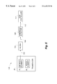
- FIG. 8 is a block diagram of components of a disk drive for purposes of illustrating where the filter and threshold detector of the present invention may be located.
- FIG. 5 is a block diagram of the flying height monitoring system, generally designated 100 , which monitors the flying height of the transducer 20 during a write operation in accordance with the present invention.
- the system 100 includes the transducer 20 that contains the write element 34 and the MR read element 44 .
- the MR read element 44 generates a readback signal, which is an analog voltage signal, at line 102 .
- the readback signal includes a thermally induced signal with a relatively low frequency content and a magnetically induced signal with a relatively high frequency content.
- the thermally induced signal is caused by temperatures changes of the MR read element 44
- the magnetically induced signal is caused by magnetic flux in the MR read element 44 generated by the write element 34 to record data on the disk 12 .
- System 100 also includes a filter 104 for receiving the readback signal and filtering out the magnetically induced signal to provide the thermally induced signal at line 106 , a threshold detector 108 for receiving the thermally induced signal and generating a digital high fly write detection signal at line 110 when the magnitude of the thermally induced signal exceeds a threshold value, and a disk controller 112 for modifying the write operation in response to the high fly write detection signal.
- a filter 104 for receiving the readback signal and filtering out the magnetically induced signal to provide the thermally induced signal at line 106
- a threshold detector 108 for receiving the thermally induced signal and generating a digital high fly write detection signal at line 110 when the magnitude of the thermally induced signal exceeds a threshold value
- a disk controller 112 for modifying the write operation in response to the high fly write detection signal.
- the write element 34 and the MR read element 44 are mechanically coupled to one another and fly at roughly the same height above the disk surface 48 .
- the write element 34 and the MR read element 44 are located in close proximity to one another, and a bias current is applied to the MR read element during the write operation.
- the write element 34 generates magnetic flux that not only records magnetic polarity transitions on the disk 12 , but also creates the magnetically induced signal in the MR read element 44 .
- the magnetic flux, and ensuing magnetically induced signal have a frequency content of about 5 MHz.
- the MR read element 44 generates a thermally induced signal that arises from temperature changes of the MR read element 44 .
- the thermally induced signal can be a thermal asperity, which occurs when the MR read element strikes an object, such as contamination or an aberration on the surface of the disk 12 .
- the thermally induced signal can also result from changes in flying height of the MR read element 44 since the disk 12 provides a heat sink for the MR read element 44 .
- the frequency content of the thermally induced signal depends on various factors, such as the thermal time constant of the MR read element 44 , and in the case of a thermal asperity, the force of the collision or friction between the MR read element 44 and the object it strikes. However, in the system 100 , the frequency content of the thermally induced signal is at most 3 MHz, which the inventors believe to be a typical upper limit for thermally induced signals from MR read elements in disk drives.
- the MR read element 44 undergoes a rapid increase in flying height, and therefore has less of its heat absorbed by the disk 12 , the rapid temperature increase of the MR read element 44 induces a thermal signal that indicates it is likely (or at least a significant possibility) that the transducer 20 shall fly too high.
- rapid decreases in flying height are often followed by rapid increases in flying height. For instance, if the transducer 20 undergoes a rapid decrease in flying height and strikes an object on the surface of the disk 12 , causing a thermal asperity in the MR read element 44 , it is likely (or at least a significant possibility) that the transducer 20 shall bounce off the object and fly too high. Likewise, if the transducer 20 undergoes a rapid decrease in flying height and the MR read element 44 rapidly cools due to its close proximity to the disk 12 , it is likely (or at least a significant possibility) that the transducer 20 shall bounce off the disk 12 and fly too high.
- the present invention utilizes this phenomena to take appropriate corrective measures, thereby increasing the reliability and integrity of the write operation.
- the filter 104 isolates the relatively low frequency content thermally induced signal from the relatively high frequency content magnetically induced signal.
- the filter 104 is a low pass filter designed to have a high-frequency cutoff great enough to transfer thermally induced signals, such as thermal asperities, but lower than the frequency content of the magnetic flux reversals used for writing data to the disk 12 .
- the high-frequency cutoff of the filter 104 is sufficient to discriminate between the low frequency content thermal component and the high frequency content magnetic component of the readback signal.
- a bandpass filter may be used instead of a lowpass filter.
- a Butterworth-type filter having a steep cutoff is preferred as an analog filtering technique. The steep cutoff features of Butterworth-type filters may also be obtained using known digital techniques.
- the frequency response of the filter 104 may also be programmable using known analog or digital techniques.
- the thermally induced signal at line 106 is applied to the threshold detector 108 .
- the threshold detector 108 compares the magnitude of the thermally induced signal with a predetermined threshold value, which may be programmable, and which is based upon a thermal event that is expected to produce a flying height that exceeds a predetermined maximum value, that is, a high fly write. If the magnitude of the thermally induced signal is greater than the threshold value, the threshold detector 108 generates the fly high write detection signal at line 110 . This is accomplished by asserting a logical one at line 110 . Otherwise, the threshold detector 108 indicates the absence of high fly write detection by asserting a logical zero at line 110 .
- the disk controller 112 which is a microprocessor, performs the necessary modifications to the write operation.
- FIGS. 6 and 7 are flowcharts which describe examples of modifications to the write operation that the disk controller 112 performs in response to the high fly write detection signal.
- step 120 the write element 34 begins writing to a sector of the disk 12 .
- the threshold detector 108 determines whether the thermally induced signal exceeds the threshold value. If not, decision step 124 determines whether the entire sector has been written to. If so, decision step 124 branches to completion step 126 ; if not, decision step 124 branches back to decision step 122 . If, on the other hand, in decision step 122 , the threshold detector 108 determines that the thermally induced signal exceeds the threshold value, then in step 128 the write element 34 stops writing, in step 130 the disk makes one revolution, and in step 132 the write element 34 begins writing to the same sector.
- decision step 134 the threshold detector 108 determines whether the thermally induced signal exceeds the threshold value. If not, decision step 136 determines whether the entire sector has been written to. If so, decision step 136 branches to completion step 126 ; if not, decision step 136 branches back to decision step 134 . If, on the other hand, in decision step 134 , the threshold detector 108 determines that the thermally induced signal exceeds the threshold value, then in step 138 the write element 34 stops writing to the sector, in step 140 the sector is marked as defective in a bad sector bit map (in which case the disk drive no longer writes to that sector), in step 142 a new sector is selected, and in step 120 the write operation begins again at the new sector.
- step 144 a counter is initialized to zero.
- step 146 the write element 34 begins writing to a sector of the disk 12 .
- step 148 the threshold detector 108 determines whether the thermally induced signal exceeds the threshold value. If not, decision step 150 determines whether the entire sector has been written to. If so, decision step 150 branches to completion step 152 ; if not, decision step 150 branches back to decision step 148 .
- step 148 the threshold detector 108 determines that the thermally induced signal exceeds the threshold value
- step 154 the write element 34 continues writing data to the disk 12 until the entire sector has been written to, and in step 156 , the written data continues to be retained in a buffer memory in the disk controller 112 .
- step 158 the MR read element 44 reads the data from the sector previously written to, and decision step 160 , the read data is compared with the buffer memory data to determine whether or not they match.
- the read verification operation in step 160 can be performed by evaluating the read data with error correction code data stored in the buffer memory. If the read data and buffer memory data match, decision step 160 branches to completion step 152 ; if not, decision step 160 branches to step 162 where the counter is incremented, and decision step 164 determines whether the counter is greater than one. If not (in which case less than two unsuccessful attempts have been made to write to the sector), decision step 164 branches to step 146 and another attempt is made at writing to the sector.
- step 166 the sector is marked as defective in a bad sector bit map, in step 168 a new sector is selected, and in step 144 the write operation begins again at the new sector.
- the write element 34 may also write over parts of adjacent tracks and render data on the adjacent tracks unreadable. This may result in the data on adjacent tracks becoming permanently unrecoverable, thereby severely degrading the reliability of the disk drive 10 . In order to reduce the likelihood of this occuring, the write operation can be aborted immediately and the sector marked as bad in response to the first high fly write detection signal arising from that sector.
- a preamplifier which includes the filter 104 and the threshold detector 108 can terminate the write signal to the write element 34 in response to the high fly write detection signal, independently of the disk controller 112 or other circuitry external to the preamplifier, thereby reducing the time that the write element 34 writes to the disk 12 after the high fly write detection signal occurs.
- the preamplifier is an integrated circuit chip, separate from other circuitry in the disk drive 10 , which includes a write driver connected to the write element 34 and a read amplifier connected to the MR read element 44 .
- the write driver converts a digital write signal into a polarity-switching write signal with sufficient current to drive the write element 34 , and the read amplifier amplifies the readback signal from the MR read element 44 , as is conventional.
- the preamplifier can contain control logic which prevents the write signal from driving the write element 34 , thereby terminating the magnetic flux generated by the write element 34 , in response to the high fly write detection signal, independently of any control signals from circuitry external to the preamplifier.
- the preamplifier can prevent the write element 34 from writing further to the disk 12 without waiting for the disk controller 112 or other external circuitry to process the high fly write detection signal and send the preamplifier appropriate instructions. Thereafter, the preamplifier can allow a subsequent write signal to drive the write element 34 in response to a control signal from the disk controller 112 .
- the sensitivity of the system 100 to thermally induced signals can be increased by increasing the bias current in the MR read element 44 during the write operation. That is, instead of using the same bias current during the read and write operations, the bias current can be increased during the write operation. Increasing the bias current effectively cubes the thermal sensitivity of the MR read element 44 .
- the readback signal (in volts) is equal to the bias current (I) through the MR read element 44 multiplied by the resistance (R) of the MR read element 44 . Furthermore, the change in temperature of the MR read element 44 is proportional to I 2 . Since the change in resistance is proportional to the change in temperature, the change in resistance is also proportional to I 2 . Accordingly, by multiplying the current, I, by the change in resistance, which is proportional to I 2 , the readback signal changes by a value proportional to the current cubed, I 3 .
- the bias current makes the system 100 more sensitive to changes in flying height.
- increasing the bias current tends to reduce the life span of the MR read element 44 .
- the bias current can be increased during write operations.
- the bias current is increased by a relatively small amount for a relatively short time period in order to reduce or eliminate unwanted thermal effects and avoid significantly reducing the life span of the MR read element 44 .
- the readback signal should be used for read operations and the flying height monitoring function after it has reached a steady-state temperature. If, for instance, a typical bias current is increased by 20% for a period of 100 nanoseconds, the MR read element 44 reaches a steady-state temperature in approximately 2 nanoseconds after the bias current is increased, at which point it can be used for the flying height monitoring function.
- this approach increases the sensitivity of MR read element 44 by about 73% without injecting thermally induced signals due to bias current changes during the flying height monitoring function or significantly reducing the life span of MR read element 44 .
- the MR read element 44 when the bias current is subsequently decreased to the baseline bias current used during the read operation, the MR read element 44 rapidly reaches a steady-state temperature to avoid thermal asperities induced by bias current changes during the read operation.
- the bias current can be increased by other amounts, such as 50%, depending on factors such as the magnitude of the thermally induced signal, the sensitivity of the threshold detector 108 , the ability of the read channel to identify thermal asperities during read operations, and so on.
- the thermally induced signal is created by relatively rapid changes to the flying height of the transducer 20 . Over time, however, debris may gradually accumulate on the transducer 20 which result in high fly writes without creating a thermally induced signal that exceeds the threshold value of the threshold detector 108 . The gradual accumulation of debris on the transducer 20 can be ascertained, for instance, by detecting an increase in the number of retries during servo or data read operations.
- thermal signal measurements based on the thermally induced signals generated by the MR read element 44 are taken the first time disk drive 10 becomes operational. Such measurements may be taken over sections of the disk 12 and recorded as reference values on the disk 12 or in non-volatile memory of a host computer. Periodically (for example, every three months), additional measurements can be taken during normal operation of the disk drive 10 , and a comparison can be made between the stored reference values and the subsequent measurements. If the differences between the stored reference values and the subsequent measurements exceed a predetermined value, an end user of the disk drive 10 can be notified to back up the data contained in the disk drive 10 and/or bring the disk drive 10 in for servicing. As another alternative, the transducer 20 can be instructed to vibrate in an effort to shake off the accumulated debris. If such vibration is not successful, the aforementioned notification may be provided to the user. Of course, the above are only examples of actions that may be taken.
- FIG. 8 shows portions of the disk drive 10 which include the MR read element 44 , a preamplifier 200 , a read channel 202 , the disk controller 112 , and an interface 204 .
- a host computer 206 which is external to the disk drive 10 , communicates with the disk drive 10 via the interface 204 .
- the filter 104 and the threshold detector 108 may be located in either the preamplifier 200 or the read channel 202 . Of course, these components may placed in other locations in the disk drive 10 .
- control logic can be added between the threshold detector 108 and the disk controller 112 which receives other warning signals, such as a shock detection signal from a shock sensor, and generates a write unsafe signal (WUS) in response to any of the warning signals.
- WUS write unsafe signal
- the high fly write detection signal can be treated as a write unsafe signal or an interrupt signal by the disk controller 112 .
- the thermally induced signal can be evaluated for positive threshold detection, negative threshold detection, or both. Accordingly, the threshold detector can generate a warning signal indicative of a high fly write, a low fly write, or both.
- the thermally induced signal may have a maximum frequency content of 2 MHz, 1 MHz, or lower, and as the bit transfer rate increases, the flux reversals during the write operation may have a minimum frequency content of 6 MHz, 10 MHz, or higher.
- the invention is well-suited for disk drives with a variety of data transfer rates, and more particularly, a variety of frequency contents in the thermally induced signal and the magnetically induced signal.
- other observed differences between the thermally induced signal and the magnetically induced signal can be used to isolate the thermally induced signal from the magnetically induced signal.
Abstract
Description
Claims (60)
Priority Applications (1)
| Application Number | Priority Date | Filing Date | Title |
|---|---|---|---|
| US09/357,094 US6452735B1 (en) | 1999-07-19 | 1999-07-19 | Disk drive that monitors the flying height of a dual element transducer using a thermally induced signal during write operations |
Applications Claiming Priority (1)
| Application Number | Priority Date | Filing Date | Title |
|---|---|---|---|
| US09/357,094 US6452735B1 (en) | 1999-07-19 | 1999-07-19 | Disk drive that monitors the flying height of a dual element transducer using a thermally induced signal during write operations |
Publications (1)
| Publication Number | Publication Date |
|---|---|
| US6452735B1 true US6452735B1 (en) | 2002-09-17 |
Family
ID=23404267
Family Applications (1)
| Application Number | Title | Priority Date | Filing Date |
|---|---|---|---|
| US09/357,094 Expired - Lifetime US6452735B1 (en) | 1999-07-19 | 1999-07-19 | Disk drive that monitors the flying height of a dual element transducer using a thermally induced signal during write operations |
Country Status (1)
| Country | Link |
|---|---|
| US (1) | US6452735B1 (en) |
Cited By (62)
| Publication number | Priority date | Publication date | Assignee | Title |
|---|---|---|---|---|
| US20020071196A1 (en) * | 2000-11-02 | 2002-06-13 | Chapin Mark A. | Fly height detector |
| US20030156340A1 (en) * | 2002-02-15 | 2003-08-21 | International Business Machines Corporation | Method and apparatus for predicting write failure resulting from flying height modulation |
| US20030182070A1 (en) * | 2002-03-20 | 2003-09-25 | Jun Zhu | New defect detection technique for media certification |
| US20030210486A1 (en) * | 2002-05-07 | 2003-11-13 | International Business Machines Corporation | Method for look-ahead thermal sensing in a data storage device |
| US6687081B1 (en) * | 2000-05-15 | 2004-02-03 | Maxtor Corporation | Disk drive using seek profile to enhance fly height control |
| US6711628B1 (en) * | 2002-02-22 | 2004-03-23 | Western Digital Technologies, Inc. | Disk drive aborting a write command before a last target sector reached if an abnormal condition detected and selecting a second command according to a rotational positioning optimization algorithm |
| US20040075942A1 (en) * | 2002-05-30 | 2004-04-22 | Bajorek Christopher H. | Lapping a head while powered up to eliminate expansion of the head due to heating |
| US20040085670A1 (en) * | 2002-11-05 | 2004-05-06 | Seagate Technology Llc | Method for measuring pad wear of padded slider with MRE cooling effect |
| US6751038B1 (en) * | 1999-10-29 | 2004-06-15 | Kabushiki Kaisha Toshiba | Data write control system and method therefor |
| US6764006B1 (en) * | 2002-07-30 | 2004-07-20 | Storage Technology Corporation | Apparatus and/or method to reduce bias current for MR reader during read only operation |
| US20040160693A1 (en) * | 2003-02-07 | 2004-08-19 | Meyer Dallas W. | Method of calibrating magnetic storage medium bi-directional recording head |
| US20050024761A1 (en) * | 2003-07-31 | 2005-02-03 | Seagate Technology Llc | Dynamic measurement of head media spacing modulation |
| US6854022B1 (en) * | 2002-02-22 | 2005-02-08 | Western Digital Technologies, Inc. | Disk drive using rotational position optimization algorithm to facilitate write verify operations |
| US20050046983A1 (en) * | 2003-08-29 | 2005-03-03 | Walton Fong | Method, apparatus and program storage device for sensing increased resistance changes in an MR element to detect MR sensor events |
| US20050094300A1 (en) * | 2003-10-31 | 2005-05-05 | Kabushiki Kaisha Toshiba | Method and apparatus for write control in a disk drive |
| US20050129090A1 (en) * | 2003-09-02 | 2005-06-16 | Texas Instruments, Inc. | Temperature compensation systems and methods for use with read/write heads in magnetic storage devices |
| US6975467B1 (en) | 2000-10-11 | 2005-12-13 | Maxtor Corporation | Method and apparatus for high fly write detection in a disk drive |
| US7023645B1 (en) * | 2002-05-03 | 2006-04-04 | Maxtor Corporation | Read error recovery method and apparatus |
| US7027251B1 (en) | 2002-01-04 | 2006-04-11 | Maxtor Corporation | Method and apparatus to control pole tip protrusion |
| US20060092550A1 (en) * | 2004-11-02 | 2006-05-04 | Hitachi Global Storage Technologies Netherlands B.V. | Data reliability improvement at low temperature |
| US7076604B1 (en) | 2002-12-24 | 2006-07-11 | Western Digital Technologies, Inc. | Disk drive employing a disk command data structure for tracking a write verify status of a write command |
| US7124625B1 (en) | 2005-05-17 | 2006-10-24 | Hitachi Global Storage Technologies Netherlands B.V. | Glide-height disk-tester and method of operation |
| US7139141B1 (en) | 2003-05-12 | 2006-11-21 | Storage Technology Corporation | System and method for read/write optimization |
| US20070002486A1 (en) * | 2005-05-09 | 2007-01-04 | Samsung Electronics Co., Ltd. | Method of controlling write strength of HDD and recording medium having recorded thereon program suitable for same |
| US7199960B1 (en) | 2001-12-11 | 2007-04-03 | Maxtor Corporation | Disk drive with AC exciter for head/disk interface |
| US7224548B1 (en) | 2002-01-04 | 2007-05-29 | Maxtor Corporation | Determining contact write current in disk drive using position error signal variance |
| US20070217051A1 (en) * | 2006-03-14 | 2007-09-20 | Yong Shen | System and method for determining head-disk contact in a magnetic recording disk drive by magnetoresistive signal amplitude |
| US20070268624A1 (en) * | 2006-05-22 | 2007-11-22 | Hitachi Global Storage Technologies | Dual polarity bias for prolonging the life of a heating element in magnetic data storage devices |
| US20080100954A1 (en) * | 2006-10-25 | 2008-05-01 | Samsung Electronics Co., Ltd. | Control method to reduce settle TMR in hard disk drives |
| US20080130156A1 (en) * | 2006-09-13 | 2008-06-05 | Hitachi Global Storage Technologies Netherlands B.V. | Disk drive with nonvolatile memory for storage of failure-related data |
| US20080247095A1 (en) * | 2007-04-05 | 2008-10-09 | Samsung Electronics Co., Ltd. | Method and apparatus for temperature sensing in a hard disk drive |
| US20080278835A1 (en) * | 2006-08-25 | 2008-11-13 | Seagate Technology, Llc | Monitoring transducer potential to detect an operating condition |
| CN100461267C (en) * | 2005-12-27 | 2009-02-11 | 日立环球储存科技荷兰有限公司 | System and method for calibrating and controlling a fly-height actuator in a magnetic recording disk drive |
| US20090046547A1 (en) * | 2007-08-17 | 2009-02-19 | Thomas Robert Albrecht | System, method, and apparatus for characterizing, tracking, and segregating known defective disk regions on patterned disks |
| US7551384B1 (en) * | 2005-10-07 | 2009-06-23 | Seagate Technology Llc | Systems and methods for calibrating a read/write channel of a hard disk drive |
| US20090195936A1 (en) * | 2008-02-04 | 2009-08-06 | Western Digital Technologies, Inc. | Disk drive servoing off of first head while determining fly height for second head |
| US7595948B1 (en) * | 2003-10-24 | 2009-09-29 | Marvell International Ltd. | Thermal asperity detection for perpendicular magnetic recording |
| US20090296264A1 (en) * | 2003-07-29 | 2009-12-03 | Meyer Dallas W | Integrated recording head with bidirectional actuation |
| US7675707B1 (en) | 2008-11-21 | 2010-03-09 | Western Digital Technologies, Inc. | Disk drive employing repeatable disturbance compensation for fly height control |
| US7724461B1 (en) | 2007-12-21 | 2010-05-25 | Western Digital Technologies, Inc. | Determining head non-linearity in a disk drive |
| US7760458B1 (en) | 2008-08-12 | 2010-07-20 | Western Digital Technologies, Inc. | Disk drive adjusting head bias during servo synchronization to compensate for over/under sensitivity |
| US7796356B1 (en) | 2009-05-04 | 2010-09-14 | Western Digital (Fremont), Llc | Head integrated touchdown sensor for hard disk drives |
| US7800858B1 (en) | 2009-05-04 | 2010-09-21 | Western Digital (Fremont), Llc | Differential head integrated touchdown sensors for hard disk drives |
| US7804657B1 (en) | 2007-06-11 | 2010-09-28 | Western Digital Technologies, Inc. | Setting an operating bias current for a magnetoresistive head using ratio of target voltage and measured voltage |
| US7839595B1 (en) | 2008-01-25 | 2010-11-23 | Western Digital Technologies, Inc. | Feed forward compensation for fly height control in a disk drive |
| US7849585B1 (en) | 2004-04-05 | 2010-12-14 | Meyer Dallas W | Micropositioning recording head for a magnetic storage device |
| US7872824B1 (en) * | 2007-06-11 | 2011-01-18 | Western Digital (Fremont), Llc | Setting an operating bias current for a magnetoresistive head by computing a target operating voltage |
| US7916420B1 (en) | 2010-05-14 | 2011-03-29 | Western Digital Technologies, Inc. | Disk drive employing comb filter for repeatable fly height compensation |
| US8059357B1 (en) | 2010-03-18 | 2011-11-15 | Western Digital Technologies, Inc. | Disk drive adjusting fly height when calibrating head/disk contact |
| US8139310B1 (en) | 2010-01-06 | 2012-03-20 | Western Digital Technologies, Inc. | Fly height sensor control circuit |
| US8279559B1 (en) | 2009-01-02 | 2012-10-02 | Meyer Dallas W | Process for creating discrete track magnetic recording media including an apparatus having a stylus selectively applying stress to a surface of the recording media |
| US8300338B1 (en) | 2010-09-30 | 2012-10-30 | Western Digital Technologies, Inc. | Disk drive correlating different fly height measurements to verify disk warpage |
| US8320069B1 (en) | 2010-03-18 | 2012-11-27 | Western Digital Technologies, Inc. | Disk drive detecting positive correlation in fly height measurements |
| US8427770B1 (en) | 2011-09-02 | 2013-04-23 | WD Media, LLC | Discriminating between protrusion defects and recess defects on a disk recording medium |
| US8482873B1 (en) | 2008-02-18 | 2013-07-09 | Western Digital Technologies, Inc. | Disk drive employing pulse width modulation of head control signal |
| US8665547B1 (en) | 2012-08-17 | 2014-03-04 | Western Digital Technologies, Inc. | Disk drive multiplexing read signal and fly height signal to a transmission line |
| EP2704144A3 (en) * | 2012-08-29 | 2014-04-23 | Seagate Technology LLC | Magnetic element with multiple selective transducing elements |
| US8837081B1 (en) | 2011-12-06 | 2014-09-16 | Western Digital (Fremont), Llc | Laminated touchdown sensor for hard disk drives |
| US9047902B1 (en) | 2011-06-15 | 2015-06-02 | Western Digital (Fremont), Llc | Touchdown sensor having a more stable crystal structure for use in hard disk drives |
| US9947353B1 (en) * | 2017-07-26 | 2018-04-17 | Seagate Technology Llc | Magnetic recording system employing passive thermal asperity avoidance |
| US10147455B1 (en) * | 2017-10-31 | 2018-12-04 | Avago Technologies International Sales Pte. Limited | Sensor circuit supporting multiple transducers with dedicated and shared terminals |
| US10217481B1 (en) * | 2018-03-19 | 2019-02-26 | Western Digital Technologies, Inc. | Data storage device employing low duty cycle square wave to detect head touchdown |
Citations (20)
| Publication number | Priority date | Publication date | Assignee | Title |
|---|---|---|---|---|
| US3979775A (en) | 1975-09-08 | 1976-09-07 | International Business Machines Corporation | Magnetoresistive multitransducer assembly with compensation elements for thermal drift and bias balancing |
| US4669011A (en) * | 1985-05-03 | 1987-05-26 | Eastman Kodak Company | Slider assembly with dynamically positionable transducer |
| US4703378A (en) | 1984-03-01 | 1987-10-27 | Sony Corporation | Magnetic transducer head utilizing magnetoresistance effect |
| US4777544A (en) | 1986-08-15 | 1988-10-11 | International Business Machine Corporation | Method and apparatus for in-situ measurement of head/recording medium clearance |
| US5082827A (en) | 1990-06-01 | 1992-01-21 | University Of Colorado Foundation, Inc. | Recording head suspension utilizing superconductor means |
| US5130866A (en) | 1990-07-17 | 1992-07-14 | International Business Machines Corporation | Method and circuitry for in-situ measurement of transducer/recording medium clearance and transducer magnetic instability |
| US5168413A (en) | 1990-11-30 | 1992-12-01 | Ibm Corporation | Transducer head flying height monitoring methods and apparatus for disk drive system |
| US5260836A (en) | 1989-11-29 | 1993-11-09 | Sony Corporation | Apparatus for reproducing digital and analog audio signals |
| US5309295A (en) | 1992-10-08 | 1994-05-03 | International Business Machines Corporation | Method and apparatus for biasing a magneto-resistive head |
| US5377058A (en) | 1992-12-31 | 1994-12-27 | International Business Machines Corporation | Fly height servo control of read/write head suspension |
| US5410439A (en) | 1992-05-19 | 1995-04-25 | International Business Machines Corporation | Disk file with clearance and glide measurement and early head crash warning |
| US5412519A (en) | 1993-08-26 | 1995-05-02 | International Business Machines Corporation | Optimization of disk drive spindle speed during low power mode |
| US5436773A (en) | 1994-06-10 | 1995-07-25 | International Business Machines Corporation | Enhanced linearity range for magneto resistive transducer servo by changing the direction of the bias current |
| US5461517A (en) | 1993-01-22 | 1995-10-24 | Hitachi, Ltd. | Magneto-resistance effect type of recording/reproducing head |
| US5909330A (en) | 1996-12-12 | 1999-06-01 | Maxtor Corporation | Method and apparatus for detecting head flying height in a disk drive |
| US6088176A (en) * | 1993-04-30 | 2000-07-11 | International Business Machines Corporation | Method and apparatus for separating magnetic and thermal components from an MR read signal |
| US6104563A (en) * | 1998-01-30 | 2000-08-15 | Maxtor Corporation | Bias modulated MR head used to minimize or eliminate thermal signals |
| US6104557A (en) * | 1996-05-31 | 2000-08-15 | Fujitsu Limited | Magnetic disk reproduction with offset compensation for thermal asperity |
| US6130793A (en) * | 1996-09-30 | 2000-10-10 | Fujitsu Limited | Thermal asperity detection method, thermal asperity compensation method, magnetic disk unit and retry method therefor |
| US6216242B1 (en) * | 1998-01-08 | 2001-04-10 | Seagate Technology Llc | Multiple-track magneto-resistive certification and thermal asperity test head |
-
1999
- 1999-07-19 US US09/357,094 patent/US6452735B1/en not_active Expired - Lifetime
Patent Citations (20)
| Publication number | Priority date | Publication date | Assignee | Title |
|---|---|---|---|---|
| US3979775A (en) | 1975-09-08 | 1976-09-07 | International Business Machines Corporation | Magnetoresistive multitransducer assembly with compensation elements for thermal drift and bias balancing |
| US4703378A (en) | 1984-03-01 | 1987-10-27 | Sony Corporation | Magnetic transducer head utilizing magnetoresistance effect |
| US4669011A (en) * | 1985-05-03 | 1987-05-26 | Eastman Kodak Company | Slider assembly with dynamically positionable transducer |
| US4777544A (en) | 1986-08-15 | 1988-10-11 | International Business Machine Corporation | Method and apparatus for in-situ measurement of head/recording medium clearance |
| US5260836A (en) | 1989-11-29 | 1993-11-09 | Sony Corporation | Apparatus for reproducing digital and analog audio signals |
| US5082827A (en) | 1990-06-01 | 1992-01-21 | University Of Colorado Foundation, Inc. | Recording head suspension utilizing superconductor means |
| US5130866A (en) | 1990-07-17 | 1992-07-14 | International Business Machines Corporation | Method and circuitry for in-situ measurement of transducer/recording medium clearance and transducer magnetic instability |
| US5168413A (en) | 1990-11-30 | 1992-12-01 | Ibm Corporation | Transducer head flying height monitoring methods and apparatus for disk drive system |
| US5410439A (en) | 1992-05-19 | 1995-04-25 | International Business Machines Corporation | Disk file with clearance and glide measurement and early head crash warning |
| US5309295A (en) | 1992-10-08 | 1994-05-03 | International Business Machines Corporation | Method and apparatus for biasing a magneto-resistive head |
| US5377058A (en) | 1992-12-31 | 1994-12-27 | International Business Machines Corporation | Fly height servo control of read/write head suspension |
| US5461517A (en) | 1993-01-22 | 1995-10-24 | Hitachi, Ltd. | Magneto-resistance effect type of recording/reproducing head |
| US6088176A (en) * | 1993-04-30 | 2000-07-11 | International Business Machines Corporation | Method and apparatus for separating magnetic and thermal components from an MR read signal |
| US5412519A (en) | 1993-08-26 | 1995-05-02 | International Business Machines Corporation | Optimization of disk drive spindle speed during low power mode |
| US5436773A (en) | 1994-06-10 | 1995-07-25 | International Business Machines Corporation | Enhanced linearity range for magneto resistive transducer servo by changing the direction of the bias current |
| US6104557A (en) * | 1996-05-31 | 2000-08-15 | Fujitsu Limited | Magnetic disk reproduction with offset compensation for thermal asperity |
| US6130793A (en) * | 1996-09-30 | 2000-10-10 | Fujitsu Limited | Thermal asperity detection method, thermal asperity compensation method, magnetic disk unit and retry method therefor |
| US5909330A (en) | 1996-12-12 | 1999-06-01 | Maxtor Corporation | Method and apparatus for detecting head flying height in a disk drive |
| US6216242B1 (en) * | 1998-01-08 | 2001-04-10 | Seagate Technology Llc | Multiple-track magneto-resistive certification and thermal asperity test head |
| US6104563A (en) * | 1998-01-30 | 2000-08-15 | Maxtor Corporation | Bias modulated MR head used to minimize or eliminate thermal signals |
Cited By (90)
| Publication number | Priority date | Publication date | Assignee | Title |
|---|---|---|---|---|
| US6751038B1 (en) * | 1999-10-29 | 2004-06-15 | Kabushiki Kaisha Toshiba | Data write control system and method therefor |
| US6687081B1 (en) * | 2000-05-15 | 2004-02-03 | Maxtor Corporation | Disk drive using seek profile to enhance fly height control |
| US6975467B1 (en) | 2000-10-11 | 2005-12-13 | Maxtor Corporation | Method and apparatus for high fly write detection in a disk drive |
| US20020071196A1 (en) * | 2000-11-02 | 2002-06-13 | Chapin Mark A. | Fly height detector |
| US6785081B2 (en) * | 2000-11-02 | 2004-08-31 | Seagate Technology Llc | Fly height detector |
| US7199960B1 (en) | 2001-12-11 | 2007-04-03 | Maxtor Corporation | Disk drive with AC exciter for head/disk interface |
| US7224548B1 (en) | 2002-01-04 | 2007-05-29 | Maxtor Corporation | Determining contact write current in disk drive using position error signal variance |
| US7027251B1 (en) | 2002-01-04 | 2006-04-11 | Maxtor Corporation | Method and apparatus to control pole tip protrusion |
| US7486457B2 (en) * | 2002-02-15 | 2009-02-03 | Hitachi Global Storage Technologies Netherlands B.V. | Method and apparatus for predicting write failure resulting from flying height modulation |
| US20030156340A1 (en) * | 2002-02-15 | 2003-08-21 | International Business Machines Corporation | Method and apparatus for predicting write failure resulting from flying height modulation |
| US6711628B1 (en) * | 2002-02-22 | 2004-03-23 | Western Digital Technologies, Inc. | Disk drive aborting a write command before a last target sector reached if an abnormal condition detected and selecting a second command according to a rotational positioning optimization algorithm |
| US6854022B1 (en) * | 2002-02-22 | 2005-02-08 | Western Digital Technologies, Inc. | Disk drive using rotational position optimization algorithm to facilitate write verify operations |
| US20030182070A1 (en) * | 2002-03-20 | 2003-09-25 | Jun Zhu | New defect detection technique for media certification |
| US7023645B1 (en) * | 2002-05-03 | 2006-04-04 | Maxtor Corporation | Read error recovery method and apparatus |
| US6956707B2 (en) * | 2002-05-07 | 2005-10-18 | Hitachi Global Storage Technologies Netherlands B.V. | Method for look-ahead thermal sensing in a data storage device |
| US20030210486A1 (en) * | 2002-05-07 | 2003-11-13 | International Business Machines Corporation | Method for look-ahead thermal sensing in a data storage device |
| US7911736B2 (en) | 2002-05-30 | 2011-03-22 | Wd Media, Inc. | Storage device and method of using a head that has a concave surface when powered down |
| US6857937B2 (en) | 2002-05-30 | 2005-02-22 | Komag, Inc. | Lapping a head while powered up to eliminate expansion of the head due to heating |
| US20050164607A1 (en) * | 2002-05-30 | 2005-07-28 | Bajorek Christopher H. | Lapping a head while powered up to eliminate expansion of the head due to heating |
| US20040075942A1 (en) * | 2002-05-30 | 2004-04-22 | Bajorek Christopher H. | Lapping a head while powered up to eliminate expansion of the head due to heating |
| US6764006B1 (en) * | 2002-07-30 | 2004-07-20 | Storage Technology Corporation | Apparatus and/or method to reduce bias current for MR reader during read only operation |
| US20040085670A1 (en) * | 2002-11-05 | 2004-05-06 | Seagate Technology Llc | Method for measuring pad wear of padded slider with MRE cooling effect |
| US7120737B1 (en) | 2002-12-24 | 2006-10-10 | Western Digital Technologies, Inc. | Disk drive employing a disk command data structure for tracking a write verify status of a write command |
| US7076604B1 (en) | 2002-12-24 | 2006-07-11 | Western Digital Technologies, Inc. | Disk drive employing a disk command data structure for tracking a write verify status of a write command |
| US7092194B2 (en) * | 2003-02-07 | 2006-08-15 | Meyer Dallas W | Method of calibrating magnetic storage medium bi-directional recording head |
| US20040160693A1 (en) * | 2003-02-07 | 2004-08-19 | Meyer Dallas W. | Method of calibrating magnetic storage medium bi-directional recording head |
| US7139141B1 (en) | 2003-05-12 | 2006-11-21 | Storage Technology Corporation | System and method for read/write optimization |
| US20110038078A1 (en) * | 2003-07-29 | 2011-02-17 | Meyer Dallas W | Integrated recording head with selective movement |
| US8284524B2 (en) | 2003-07-29 | 2012-10-09 | Meyer Dallas W | Integrated recording head with selective movement |
| US7835115B2 (en) | 2003-07-29 | 2010-11-16 | Meyer Dallas W | Integrated recording head with selective movement |
| US9070413B2 (en) | 2003-07-29 | 2015-06-30 | Dallas W. Meyer | Integrated recording head with selective movement |
| US9659594B2 (en) | 2003-07-29 | 2017-05-23 | Dallas W. Meyer | Integrated recording head with selective movement |
| US20090296264A1 (en) * | 2003-07-29 | 2009-12-03 | Meyer Dallas W | Integrated recording head with bidirectional actuation |
| US20050024761A1 (en) * | 2003-07-31 | 2005-02-03 | Seagate Technology Llc | Dynamic measurement of head media spacing modulation |
| US7038875B2 (en) | 2003-07-31 | 2006-05-02 | Seagate Technology Llc | Dynamic measurement of head media spacing modulation |
| US7054084B2 (en) * | 2003-08-29 | 2006-05-30 | Hitachi Global Storage Technologies Netherlands B.V. | Method, apparatus and program storage device for sensing increased resistance changes in an MR element to detect MR sensor events |
| US20050046983A1 (en) * | 2003-08-29 | 2005-03-03 | Walton Fong | Method, apparatus and program storage device for sensing increased resistance changes in an MR element to detect MR sensor events |
| US7097110B2 (en) | 2003-09-02 | 2006-08-29 | Texas Instruments Incorporated | Temperature compensation systems and methods for use with read/write heads in magnetic storage devices |
| US20050129090A1 (en) * | 2003-09-02 | 2005-06-16 | Texas Instruments, Inc. | Temperature compensation systems and methods for use with read/write heads in magnetic storage devices |
| US7595948B1 (en) * | 2003-10-24 | 2009-09-29 | Marvell International Ltd. | Thermal asperity detection for perpendicular magnetic recording |
| US20050094300A1 (en) * | 2003-10-31 | 2005-05-05 | Kabushiki Kaisha Toshiba | Method and apparatus for write control in a disk drive |
| US7849585B1 (en) | 2004-04-05 | 2010-12-14 | Meyer Dallas W | Micropositioning recording head for a magnetic storage device |
| US8307542B2 (en) | 2004-04-05 | 2012-11-13 | Meyer Dallas W | Micropositioning recording head for a magnetic storage device |
| US20060092550A1 (en) * | 2004-11-02 | 2006-05-04 | Hitachi Global Storage Technologies Netherlands B.V. | Data reliability improvement at low temperature |
| US7277251B2 (en) * | 2004-11-02 | 2007-10-02 | Hitachi Global Storage Technologies Netherlands B.V. | Data reliability improvement at low temperature |
| US7660059B2 (en) * | 2005-05-09 | 2010-02-09 | Samsung Electronics Co., Ltd. | Method of controlling write strength of HDD and recording medium having recorded thereon program suitable for same |
| US20070002486A1 (en) * | 2005-05-09 | 2007-01-04 | Samsung Electronics Co., Ltd. | Method of controlling write strength of HDD and recording medium having recorded thereon program suitable for same |
| US7124625B1 (en) | 2005-05-17 | 2006-10-24 | Hitachi Global Storage Technologies Netherlands B.V. | Glide-height disk-tester and method of operation |
| US7551384B1 (en) * | 2005-10-07 | 2009-06-23 | Seagate Technology Llc | Systems and methods for calibrating a read/write channel of a hard disk drive |
| CN100461267C (en) * | 2005-12-27 | 2009-02-11 | 日立环球储存科技荷兰有限公司 | System and method for calibrating and controlling a fly-height actuator in a magnetic recording disk drive |
| US20070217051A1 (en) * | 2006-03-14 | 2007-09-20 | Yong Shen | System and method for determining head-disk contact in a magnetic recording disk drive by magnetoresistive signal amplitude |
| US7292401B2 (en) * | 2006-03-14 | 2007-11-06 | Hitachi Global Storage Technologies Netherlands B.V. | System and method for determining head-disk contact in a magnetic recording disk drive by magnetoresistive signal amplitude |
| US7330336B2 (en) | 2006-05-22 | 2008-02-12 | Hitachi Global Storage Technologies Netherlands B. V. | Dual polarity bias for prolonging the life of a heating element in magnetic data storage devices |
| US20070268624A1 (en) * | 2006-05-22 | 2007-11-22 | Hitachi Global Storage Technologies | Dual polarity bias for prolonging the life of a heating element in magnetic data storage devices |
| US7656600B2 (en) | 2006-08-25 | 2010-02-02 | Seagate Technology Llc | Monitoring transducer potential to detect an operating condition |
| US20080278835A1 (en) * | 2006-08-25 | 2008-11-13 | Seagate Technology, Llc | Monitoring transducer potential to detect an operating condition |
| US8015433B2 (en) * | 2006-09-13 | 2011-09-06 | Hitachi Global Storage Technologies Netherlands B.V. | Disk drive with nonvolatile memory for storage of failure-related data |
| US20080130156A1 (en) * | 2006-09-13 | 2008-06-05 | Hitachi Global Storage Technologies Netherlands B.V. | Disk drive with nonvolatile memory for storage of failure-related data |
| US7394614B2 (en) * | 2006-10-25 | 2008-07-01 | Samsung Electronics Co., Ltd. | Control method to reduce settle TMR in hard disk drives |
| US20080100954A1 (en) * | 2006-10-25 | 2008-05-01 | Samsung Electronics Co., Ltd. | Control method to reduce settle TMR in hard disk drives |
| US20080247095A1 (en) * | 2007-04-05 | 2008-10-09 | Samsung Electronics Co., Ltd. | Method and apparatus for temperature sensing in a hard disk drive |
| US7872824B1 (en) * | 2007-06-11 | 2011-01-18 | Western Digital (Fremont), Llc | Setting an operating bias current for a magnetoresistive head by computing a target operating voltage |
| US7804657B1 (en) | 2007-06-11 | 2010-09-28 | Western Digital Technologies, Inc. | Setting an operating bias current for a magnetoresistive head using ratio of target voltage and measured voltage |
| US7852717B2 (en) * | 2007-08-17 | 2010-12-14 | Hitachi Global Storage Technologies Netherlands B.V. | System, method, and apparatus for characterizing, tracking, and segregating known defective disk regions on patterned disks |
| US20090046547A1 (en) * | 2007-08-17 | 2009-02-19 | Thomas Robert Albrecht | System, method, and apparatus for characterizing, tracking, and segregating known defective disk regions on patterned disks |
| US7724461B1 (en) | 2007-12-21 | 2010-05-25 | Western Digital Technologies, Inc. | Determining head non-linearity in a disk drive |
| US7839595B1 (en) | 2008-01-25 | 2010-11-23 | Western Digital Technologies, Inc. | Feed forward compensation for fly height control in a disk drive |
| US8780473B1 (en) | 2008-02-04 | 2014-07-15 | Western Digital Technologies, Inc. | Disk drive selecting a global digital-to-analog setting for a plurality of heads |
| US7630162B2 (en) | 2008-02-04 | 2009-12-08 | Western Digital Technologies, Inc. | Disk drive servoing off of first head while determining fly height for second head |
| US20090195936A1 (en) * | 2008-02-04 | 2009-08-06 | Western Digital Technologies, Inc. | Disk drive servoing off of first head while determining fly height for second head |
| US8482873B1 (en) | 2008-02-18 | 2013-07-09 | Western Digital Technologies, Inc. | Disk drive employing pulse width modulation of head control signal |
| US7760458B1 (en) | 2008-08-12 | 2010-07-20 | Western Digital Technologies, Inc. | Disk drive adjusting head bias during servo synchronization to compensate for over/under sensitivity |
| US7675707B1 (en) | 2008-11-21 | 2010-03-09 | Western Digital Technologies, Inc. | Disk drive employing repeatable disturbance compensation for fly height control |
| US8279559B1 (en) | 2009-01-02 | 2012-10-02 | Meyer Dallas W | Process for creating discrete track magnetic recording media including an apparatus having a stylus selectively applying stress to a surface of the recording media |
| US7796356B1 (en) | 2009-05-04 | 2010-09-14 | Western Digital (Fremont), Llc | Head integrated touchdown sensor for hard disk drives |
| US7800858B1 (en) | 2009-05-04 | 2010-09-21 | Western Digital (Fremont), Llc | Differential head integrated touchdown sensors for hard disk drives |
| US8279550B1 (en) | 2010-01-06 | 2012-10-02 | Western Digital Technologies, Inc. | Fly height sensor control circuit |
| US8139310B1 (en) | 2010-01-06 | 2012-03-20 | Western Digital Technologies, Inc. | Fly height sensor control circuit |
| US8320069B1 (en) | 2010-03-18 | 2012-11-27 | Western Digital Technologies, Inc. | Disk drive detecting positive correlation in fly height measurements |
| US8059357B1 (en) | 2010-03-18 | 2011-11-15 | Western Digital Technologies, Inc. | Disk drive adjusting fly height when calibrating head/disk contact |
| US7916420B1 (en) | 2010-05-14 | 2011-03-29 | Western Digital Technologies, Inc. | Disk drive employing comb filter for repeatable fly height compensation |
| US8300338B1 (en) | 2010-09-30 | 2012-10-30 | Western Digital Technologies, Inc. | Disk drive correlating different fly height measurements to verify disk warpage |
| US9047902B1 (en) | 2011-06-15 | 2015-06-02 | Western Digital (Fremont), Llc | Touchdown sensor having a more stable crystal structure for use in hard disk drives |
| US8427770B1 (en) | 2011-09-02 | 2013-04-23 | WD Media, LLC | Discriminating between protrusion defects and recess defects on a disk recording medium |
| US8837081B1 (en) | 2011-12-06 | 2014-09-16 | Western Digital (Fremont), Llc | Laminated touchdown sensor for hard disk drives |
| US8665547B1 (en) | 2012-08-17 | 2014-03-04 | Western Digital Technologies, Inc. | Disk drive multiplexing read signal and fly height signal to a transmission line |
| EP2704144A3 (en) * | 2012-08-29 | 2014-04-23 | Seagate Technology LLC | Magnetic element with multiple selective transducing elements |
| US9947353B1 (en) * | 2017-07-26 | 2018-04-17 | Seagate Technology Llc | Magnetic recording system employing passive thermal asperity avoidance |
| US10147455B1 (en) * | 2017-10-31 | 2018-12-04 | Avago Technologies International Sales Pte. Limited | Sensor circuit supporting multiple transducers with dedicated and shared terminals |
| US10217481B1 (en) * | 2018-03-19 | 2019-02-26 | Western Digital Technologies, Inc. | Data storage device employing low duty cycle square wave to detect head touchdown |
Similar Documents
| Publication | Publication Date | Title |
|---|---|---|
| US6452735B1 (en) | Disk drive that monitors the flying height of a dual element transducer using a thermally induced signal during write operations | |
| US7097110B2 (en) | Temperature compensation systems and methods for use with read/write heads in magnetic storage devices | |
| US7292401B2 (en) | System and method for determining head-disk contact in a magnetic recording disk drive by magnetoresistive signal amplitude | |
| US5818656A (en) | Circuitry for correction of thermal transients in the analog signal from a magnetoresistive sensor | |
| JP3645054B2 (en) | Method and apparatus for positioning a dual element magnetoresistive head | |
| US6504662B2 (en) | Apparatus for measuring and characterizing thermal asperities in a mass data storage device | |
| US6266199B1 (en) | Method of apparatus to characterize and limit the effect of disk damage in a hard disk drive | |
| JP2878257B2 (en) | Magnetic data storage device and method for removing protrusions on disk surface | |
| US5808825A (en) | Read error recovery method and apparatus for use in disk storage system | |
| US7027263B2 (en) | Apparatus for look-ahead thermal sensing in a data storage device | |
| EP2372708B1 (en) | Systems and methods for detecting head contact | |
| US6956707B2 (en) | Method for look-ahead thermal sensing in a data storage device | |
| US7656600B2 (en) | Monitoring transducer potential to detect an operating condition | |
| US6373647B1 (en) | Method of self-testing magneto-resistive heads for instability in a disk drive | |
| US6822814B2 (en) | Write head collision detection using MR read element in disc drives | |
| EP1585130A2 (en) | Read head preamplifier with thermal asperity transient control | |
| US6724550B2 (en) | Adaptive dampening of thermal asperity events in disc drives | |
| US6421193B1 (en) | Method and apparatus for detecting, logging and recovering from errors caused by multiple thermal asperities in a sector | |
| US20080291564A1 (en) | Detecting head-disk contact during off-track operations | |
| US7224548B1 (en) | Determining contact write current in disk drive using position error signal variance | |
| US7486457B2 (en) | Method and apparatus for predicting write failure resulting from flying height modulation | |
| US7054084B2 (en) | Method, apparatus and program storage device for sensing increased resistance changes in an MR element to detect MR sensor events | |
| US7525771B2 (en) | GMR spin-valve element evaluation method, magnetic head manufacturing method, and magnetic storage device | |
| KR20020045544A (en) | Hard disk drive, method and circuit for driving thereof | |
| US7259931B2 (en) | Slider design for high fly write immunity |
Legal Events
| Date | Code | Title | Description |
|---|---|---|---|
| AS | Assignment |
Owner name: MAXTOR CORPORATION, COLORADO Free format text: ASSIGNMENT OF ASSIGNORS INTEREST;ASSIGNORS:EGAN, CURTIS;LIN, GANG HERBERT;REEL/FRAME:010203/0388;SIGNING DATES FROM 19990817 TO 19990819 |
|
| STCF | Information on status: patent grant |
Free format text: PATENTED CASE |
|
| FPAY | Fee payment |
Year of fee payment: 4 |
|
| AS | Assignment |
Owner name: JPMORGAN CHASE BANK, N.A., AS ADMINISTRATIVE AGENT Free format text: SECURITY AGREEMENT;ASSIGNORS:MAXTOR CORPORATION;SEAGATE TECHNOLOGY LLC;SEAGATE TECHNOLOGY INTERNATIONAL;REEL/FRAME:022757/0017 Effective date: 20090507 Owner name: WELLS FARGO BANK, NATIONAL ASSOCIATION, AS COLLATE Free format text: SECURITY AGREEMENT;ASSIGNORS:MAXTOR CORPORATION;SEAGATE TECHNOLOGY LLC;SEAGATE TECHNOLOGY INTERNATIONAL;REEL/FRAME:022757/0017 Effective date: 20090507 |
|
| FPAY | Fee payment |
Year of fee payment: 8 |
|
| AS | Assignment |
Owner name: SEAGATE TECHNOLOGY INTERNATIONAL, CALIFORNIA Free format text: RELEASE;ASSIGNOR:JPMORGAN CHASE BANK, N.A., AS ADMINISTRATIVE AGENT;REEL/FRAME:025662/0001 Effective date: 20110114 Owner name: SEAGATE TECHNOLOGY HDD HOLDINGS, CALIFORNIA Free format text: RELEASE;ASSIGNOR:JPMORGAN CHASE BANK, N.A., AS ADMINISTRATIVE AGENT;REEL/FRAME:025662/0001 Effective date: 20110114 Owner name: SEAGATE TECHNOLOGY LLC, CALIFORNIA Free format text: RELEASE;ASSIGNOR:JPMORGAN CHASE BANK, N.A., AS ADMINISTRATIVE AGENT;REEL/FRAME:025662/0001 Effective date: 20110114 Owner name: MAXTOR CORPORATION, CALIFORNIA Free format text: RELEASE;ASSIGNOR:JPMORGAN CHASE BANK, N.A., AS ADMINISTRATIVE AGENT;REEL/FRAME:025662/0001 Effective date: 20110114 |
|
| AS | Assignment |
Owner name: THE BANK OF NOVA SCOTIA, AS ADMINISTRATIVE AGENT, Free format text: SECURITY AGREEMENT;ASSIGNOR:SEAGATE TECHNOLOGY LLC;REEL/FRAME:026010/0350 Effective date: 20110118 |
|
| AS | Assignment |
Owner name: SEAGATE TECHNOLOGY US HOLDINGS, INC., CALIFORNIA Free format text: TERMINATION AND RELEASE OF SECURITY INTEREST IN PATENT RIGHTS;ASSIGNOR:WELLS FARGO BANK, NATIONAL ASSOCIATION, AS COLLATERAL AGENT AND SECOND PRIORITY REPRESENTATIVE;REEL/FRAME:030833/0001 Effective date: 20130312 Owner name: EVAULT INC. (F/K/A I365 INC.), CALIFORNIA Free format text: TERMINATION AND RELEASE OF SECURITY INTEREST IN PATENT RIGHTS;ASSIGNOR:WELLS FARGO BANK, NATIONAL ASSOCIATION, AS COLLATERAL AGENT AND SECOND PRIORITY REPRESENTATIVE;REEL/FRAME:030833/0001 Effective date: 20130312 Owner name: SEAGATE TECHNOLOGY LLC, CALIFORNIA Free format text: TERMINATION AND RELEASE OF SECURITY INTEREST IN PATENT RIGHTS;ASSIGNOR:WELLS FARGO BANK, NATIONAL ASSOCIATION, AS COLLATERAL AGENT AND SECOND PRIORITY REPRESENTATIVE;REEL/FRAME:030833/0001 Effective date: 20130312 Owner name: SEAGATE TECHNOLOGY INTERNATIONAL, CAYMAN ISLANDS Free format text: TERMINATION AND RELEASE OF SECURITY INTEREST IN PATENT RIGHTS;ASSIGNOR:WELLS FARGO BANK, NATIONAL ASSOCIATION, AS COLLATERAL AGENT AND SECOND PRIORITY REPRESENTATIVE;REEL/FRAME:030833/0001 Effective date: 20130312 |
|
| FPAY | Fee payment |
Year of fee payment: 12 |