US6433749B1 - Antenna assembly - Google Patents
Antenna assembly Download PDFInfo
- Publication number
- US6433749B1 US6433749B1 US09/719,799 US71979901A US6433749B1 US 6433749 B1 US6433749 B1 US 6433749B1 US 71979901 A US71979901 A US 71979901A US 6433749 B1 US6433749 B1 US 6433749B1
- Authority
- US
- United States
- Prior art keywords
- antennas
- vehicle
- antenna module
- signals
- antenna
- Prior art date
- Legal status (The legal status is an assumption and is not a legal conclusion. Google has not performed a legal analysis and makes no representation as to the accuracy of the status listed.)
- Expired - Fee Related
Links
Images


Classifications
-
- H—ELECTRICITY
- H01—ELECTRIC ELEMENTS
- H01Q—ANTENNAS, i.e. RADIO AERIALS
- H01Q1/00—Details of, or arrangements associated with, antennas
- H01Q1/36—Structural form of radiating elements, e.g. cone, spiral, umbrella; Particular materials used therewith
- H01Q1/38—Structural form of radiating elements, e.g. cone, spiral, umbrella; Particular materials used therewith formed by a conductive layer on an insulating support
-
- H—ELECTRICITY
- H01—ELECTRIC ELEMENTS
- H01Q—ANTENNAS, i.e. RADIO AERIALS
- H01Q1/00—Details of, or arrangements associated with, antennas
- H01Q1/12—Supports; Mounting means
- H01Q1/1271—Supports; Mounting means for mounting on windscreens
-
- H—ELECTRICITY
- H01—ELECTRIC ELEMENTS
- H01Q—ANTENNAS, i.e. RADIO AERIALS
- H01Q1/00—Details of, or arrangements associated with, antennas
- H01Q1/27—Adaptation for use in or on movable bodies
- H01Q1/32—Adaptation for use in or on road or rail vehicles
-
- H—ELECTRICITY
- H01—ELECTRIC ELEMENTS
- H01Q—ANTENNAS, i.e. RADIO AERIALS
- H01Q1/00—Details of, or arrangements associated with, antennas
- H01Q1/44—Details of, or arrangements associated with, antennas using equipment having another main function to serve additionally as an antenna, e.g. means for giving an antenna an aesthetic aspect
-
- H—ELECTRICITY
- H01—ELECTRIC ELEMENTS
- H01Q—ANTENNAS, i.e. RADIO AERIALS
- H01Q21/00—Antenna arrays or systems
- H01Q21/28—Combinations of substantially independent non-interacting antenna units or systems
-
- H—ELECTRICITY
- H01—ELECTRIC ELEMENTS
- H01Q—ANTENNAS, i.e. RADIO AERIALS
- H01Q23/00—Antennas with active circuits or circuit elements integrated within them or attached to them
Definitions
- This invention relates to an antenna assembly of modular form for use in road vehicles.
- Car-designers generally impose severe constraints in terms of the allocated space, the permitted locations, the mechanical interfaces, the electrical interfaces, etc for these antennas.
- Glass antenna technology is used by the original equipment manufacturer and the antenna cannot be replaced or modified without replacing the window glass itself. Thus glass antenna technology is not appropriate for the upgrading of the antenna systems that may later be required when new services are introduced, or for the after-market.
- U.S. Pat. No. 5,400,039 discloses an integrated multi-layered microwave circuit in which conductive layers and dielectric layers are alternately laminated.
- a first conductive layer on one major face forms an antenna interface
- a second conductive layer on the other major face forms a circuit pattern to which discrete parts are fitted.
- the first and second conductive layers are connected to feed an antenna signal.
- Dielectric layers separate a ground layer and power source layer from each other and from the first and second conductive layers.
- the first conductive layer forming the antenna interface has three circular antenna radiators connected together with phase shifters.
- European Patent Appln. 0 590 955 (Loral Aerospace) discloses an antenna for receiving signals in a plurality of frequency bands
- European Patent Appln. 0 806 851 (Becker GmbH) discloses that an optical data bus may be in vehicular communications.
- the present invention seeks to avoid at least some of disadvantages mentioned above. In principle, it is applicable equally to transmitting antennas and receiving antennas, and the claims are to be interpreted accordingly.
- the antennas may provide for reception and/or transmission of two or more signals of the following types: FM broadcast radio, AM broadcast radio, digital audio broadcasts, analogue broadcast television, digital broadcast television, telephony, other two-way radio communications, position fixing, station keeping, vehicle guidance, vehicle security, vehicle identification, tolling, emergency calls.
- Broadcast includes both terrestrial and satellite transmissions, whether free-on-air or pay-to-receive.
- the structure may contain active systems for signal processing before transmission or after reception.
- connection means may be adapted for conveying signals relating to vehicle security to or from the vehicle separately from other signals.
- the data bus may be an optical bus.
- the structure is of material substantially transparent to electromagnetic radiation.
- At least one said antenna may be integrated into or disposed on the fabric of the structure.
- the structure may be a housing within which at least one said antenna is contained.
- the module may comprise means for mounting it on an external surface of the vehicle, and shaped to conform with the styling thereof, and/or to perform a aerodynamic function.
- At least one said active system may be disposed within the housing.
- the module may be configured as a spoiler, fairing, airdam or fin.
- At least one of the antennas may be a pattern of conductive material printed, etched or otherwise disposed on a dielectric substrate.
- the module may be shaped to conform to a surface (eg. an inner surface) of a window, window surround or body panel of the vehicle.
- the module may be mounted on an external surface of the vehicle, and shaped to conform with the styling thereof.
- the module may be configured as a spoiler, fairing or fin for mounting towards the rear of the vehicle.
- FIG. 1 illustrates the concept of the invention.
- FIG. 2 shows some possible locations in a vehicle for an antenna module according to the invention
- FIG. 3 is a system diagram of a module according to the invention.
- FIG. 4 shows an antenna module according to the invention.
- FIGS. 1 and 3 are fully captioned, reference numerals are not used in these figures. Instead the description of those figures will proceed using the captioned terms.
- the antenna module consists of a pod or other structure shaped to conform to a suitable radio-transparent inner surface of the vehicle such as a window, a non-metallic panel such as a boot (trunk) lid, roof, wing or bumper (fender).
- a suitable radio-transparent inner surface of the vehicle such as a window, a non-metallic panel such as a boot (trunk) lid, roof, wing or bumper (fender).
- the antenna systems pod contains all the antennas necessary for the reception of signals which are required for the vehicle's in-car multimedia and communication facilities such as AM/FM radio, analogue/digital television, digital audio broadcasts (DAB), global positioning system (GPS), mobile telephony (GSM), keyless entry, etc.
- AM/FM radio analogue/digital television
- DAB digital audio broadcasts
- GPS global positioning system
- GSM mobile telephony
- keyless entry etc.
- the pod also contains the electronic sub-systems, including RF amplifiers, diversity chips, switches, tuner chips and transmitters that are required to provide some or all of the in-car facilities mentioned above.
- the pod has few electrical interfaces: e,g. a 12 V or other low voltage supply, a principal network connection for a single data bus (either an optical fibre or wire bus), and a separate connection to a keyless entry security system of the vehicle.
- FIG. 2 some possible mounting positions are shown for the pod in a typical modern vehicle, here a Volkswagen Passat. VOLKSWAGEN, PASSAT and the VW logo visible in FIG. 2 are registered trade marks.
- the locations illustrated are the top of the windscreen 20 , the top 21 or bottom 22 of the rear window, the top of the fascia 23 , and a rear Spoiler 24 .
- the pod is to be mounted on a window, it conveniently can consist of an antenna portion in which the antenna patterns are formed on a transparent flexible substrate for attachment to the window and a systems portion which is located just outside the window area, e.g. along the window frame or under an adjacent head lining.
- a vehicle which employs composite panels presents a larger number of options for mounting positions.
- the pod could be incorporated in, or conformably mounted against the airdam or fairing often fitted to the cab roof of an articulated tractor unit to reduce the drag or turbulence of a tall semi-trailer.
- it could be conformably mounted behind the bumper or one of the several other glass-fibre body panels of a truck cab.
- FIG. 3 is a system block diagram of the functional units contained within the envelope of the pod.
- Optical signals containing control data generated by a man machine interface in the vehicle (MMI, shown in FIG. 1) are received, via the single optical bus, by a fibre optic transceiver and converted to electrical signals before being passed to a codec optical transceiver.
- the codec optical transceiver routes this control data to a microprocessor which then controls an AM/FM diversity tuner, a TV diversity tuners a GPS receiver and engine, a GSM transmit/receive (TX/RX) module, a DAB tuner and other service items that are connected to an I 2 C bus within the pod.
- TX/RX GSM transmit/receive
- the AM/FM diversity tuner receives its signals either from an AM antenna or from one of four FM antennas according to band selection.
- the diversity electronics of the FM tuner selects the antenna that offers the signal with the least multipath distortion.
- the diversity electronics may apply amplitude and phase weighting to some or all of the signals received by the FM antennas in order to minimise the effects of multipath distortion.
- Radio data system (RDS) information (information regarding the identity of the received station, traffic information etc) is passed to the codec optical transceiver via the RDS pre-processor and the microprocessor. Audio signals are also passed to the codec optical transceiver.
- RDS Radio data system
- the diversity electronics of the TV tuner selects one of four TV antennas that offers the signal with the least multipath distortion. Alternatively the diversity electronics may apply amplitude and phase weighting to some or all of the signals received by the TV antennas in order to minimise the effects of the nultipath distortion. Video and audio signals from the TV diversity tuner are passed to the codes optical transceiver.
- the GPS receiver and engine, GSM TX/RX module, DAB tuner and the other services each receive signals from their respective antennas.
- Other services envisaged for the future are road tolling, station keeping relative to the preceding vehicle (the pod would then be mounted to accommodate the necessary forward-looking antenna) and vehicle guidance when the necessary highway infrastructure systems are in place.
- the codec optical transceiver receives GPS data, GSM data, DAB data and other data from the GPS receiver and engine, GSM TX/RX module, DAB tuner and other services respectively.
- All the data, including status data, received by the codec optical transceiver is processed (in particular digitised, if not already digital) and packed into frames if necessary for the transmission protocol before being passed to a second fibre optic transceiver for transmission to the other devices (shown in FIG. 1) are connected to the single optical network (bus).
- control signal from the keyless entry receiver and decoder preferably is not sent with the other data over the optical network but is sent separately to the car security system.
- the keyless entry signals may be sent via the optical network.
- the single network connection carries communications from all the antennas to the control unit and other devices on the network.
- the data is coded and transmitted using a common protocol for the devices.
- MOST Media Orientated Systems Transport.
- the network passes the coded digital information in a common format so that the central processor can communicate with all other devices.
- the MOST network is wide bandwidth so that the multimedia data can be transferred using a single system clock. Alternatively asynchronous packet data can be handled as well.
- the bandwidth is programmable in real time and one node can communicate with another unencumbered. Since the intelligence is in the network it is suitable for consumer electronics applications.
- the network can be optimised for the chosen peripheral devices connected.
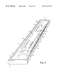
- FIG. 4 shows an open view of the pod. It comprises a two-part housing or casing, the upper part of the casing (not shown) having been removed from the lower part of the casing 1 , to reveal an antenna board 2 and the system electronics modules 3 .
- the casing of the pod is made of plastics or other suitably rigid composite material that is transparent to electromagnetic radiation.
- the casing is shaped to conform to the window and body of the cat or, when mounted as a spoiler, to the aerodynamic and aesthetic requirements.
- the antenna board comprises a copper clad laminate and provides the numerous antennas. These are formed either by etching the copper of the antenna board or by mounting separate antennas on the antenna board. Other known methods of antenna construction may be used, e.g. screen printing a silver layer in the required patterns.
- the AM antenna comprises wire windings on a ferrite rod 4 .
- the FM antennas consist of a bow-tie dipole antenna 5 , and fractal antennas 6 , 7 and 8 .
- the TV antennas are shown as bow-tie dipoles 9 , 10 , 11 and 12 .
- the GPS antenna is a patch antenna 13
- the GSM antenna is formed by a slot 14
- the keyless entry antenna is also formed by a slot 15 .
- the antennas for the other services would take the appropriate form according to the frequency of operation and radiation pattern requirements.
- Connecting lines (not shown) from the numerous antennas to electronics modules are made either by means of tracks etched in the copper of the antenna board or by means of coaxial cables or by a combination of these means.
- some or all of the antennas may be printed or etched on the surface of the casing itself, or may be integrated into it (potted) when the casing is manufactured, e.g. by injection moulding.
- All antennas and sub-systems can be tested prior to installation in the vehicle.
- Mounting can be either internal or external.
- the concept can be applied both to the OEM and after-markets.
- the invention also includes any novel features or combination of features disclosed in the specification (which term includes the claims) whether or not presently claimed.
Abstract
An antenna module for a road vehicle comprising a structure including a plurality of antennas having different functions and configured to be mounted on or conform to a surface of the vehicle, a data bus for conveying in a digital format, signals received by or to be transmitted by the antenna between the module and equipment comprised in the vehicle, and means for converting received signals into said format and for converting signals to be transmitted from that format into a form for transmission.
Description
This invention relates to an antenna assembly of modular form for use in road vehicles.
For many years a single antenna was considered sufficient to satisfy the signal reception requirements of the AM/FM radio which is commonly installed in motor vehicles. In recent years additional antennas and associated diversity electronics have been introduced in order to eliminate or reduce the audio distortions that can be experienced when driving in a multipath signal environment.
As other services, such as mobile telephone (e.g, GSM) and global positioning by satellite (GPS), have been introduced, it has been necessary to add other antennas to the motor vehicle. Further services are planned which will lead to numerous other antennas also being added to the vehicle, More than twelve antenna elements could be required for the reception of existing and currently envisaged services.
The integration of so many antennas into a vehicle presents a number of problems in the design, manufacture, installation, test, servicing and upgrading phases of the product life-cycle,.
Car-designers generally impose severe constraints in terms of the allocated space, the permitted locations, the mechanical interfaces, the electrical interfaces, etc for these antennas.
For a number of years car manufacturers have provided vehicles with antennas integrated into the rear windows, so-called glass antennas, in order to offer a lower cost alternative to the more familiar external whip or telescopic mast antennas. However, the system performance obtained with these glass antennas is often compromised because the shape or form of antennas for good electrical performance is generally not compatible with the dominant aesthetic requirements. This situation is aggravated when a large number of antennas are required. Connecting tracks are used to route the signals from (or to) the glass antenna elements. Cross-over connections to these tracks are difficult to avoid and connections to screened cables and associated electronic assemblies are relatively expensive to implement reliably.
Glass antenna technology is used by the original equipment manufacturer and the antenna cannot be replaced or modified without replacing the window glass itself. Thus glass antenna technology is not appropriate for the upgrading of the antenna systems that may later be required when new services are introduced, or for the after-market.
U.S. Pat. No. 5,400,039 (Hitachi, Ltd.) discloses an integrated multi-layered microwave circuit in which conductive layers and dielectric layers are alternately laminated. A first conductive layer on one major face forms an antenna interface, and a second conductive layer on the other major face forms a circuit pattern to which discrete parts are fitted. The first and second conductive layers are connected to feed an antenna signal. Dielectric layers separate a ground layer and power source layer from each other and from the first and second conductive layers. The first conductive layer forming the antenna interface has three circular antenna radiators connected together with phase shifters.
European Patent Appln. 0 590 955 (Loral Aerospace) discloses an antenna for receiving signals in a plurality of frequency bands, and European Patent Appln. 0 806 851 (Becker GmbH) discloses that an optical data bus may be in vehicular communications.
The present invention, at least in its preferred embodiments, seeks to avoid at least some of disadvantages mentioned above. In principle, it is applicable equally to transmitting antennas and receiving antennas, and the claims are to be interpreted accordingly.
In one aspect, the invention provides an antenna module for a road vehicle comprises a structure including a plurality of antennas for receiving and/or transmitting different types of signals, and configured to be mounted in or on the vehicle, a data bus for conveying in a digital format signals received by and/or to be transmitted by the antennas between the module and equipment comprised in the vehicle, and means for converting received signals into said format and/or for converting signals to be transmitted from that format into a form for transmission.
The antennas may provide for reception and/or transmission of two or more signals of the following types: FM broadcast radio, AM broadcast radio, digital audio broadcasts, analogue broadcast television, digital broadcast television, telephony, other two-way radio communications, position fixing, station keeping, vehicle guidance, vehicle security, vehicle identification, tolling, emergency calls. ‘Broadcast’ includes both terrestrial and satellite transmissions, whether free-on-air or pay-to-receive.
The structure may contain active systems for signal processing before transmission or after reception.
The connection means may be adapted for conveying signals relating to vehicle security to or from the vehicle separately from other signals.
The data bus may be an optical bus.
Preferably the structure is of material substantially transparent to electromagnetic radiation.
At least one said antenna may be integrated into or disposed on the fabric of the structure.
Alternatively or in addition the structure may be a housing within which at least one said antenna is contained. The module may comprise means for mounting it on an external surface of the vehicle, and shaped to conform with the styling thereof, and/or to perform a aerodynamic function.
At least one said active system may be disposed within the housing. The module may be configured as a spoiler, fairing, airdam or fin.
At least one of the antennas may be a pattern of conductive material printed, etched or otherwise disposed on a dielectric substrate.
The module may be shaped to conform to a surface (eg. an inner surface) of a window, window surround or body panel of the vehicle.
Alternatively there may be means for mounting the module on an external surface of the vehicle, and shaped to conform with the styling thereof.
The module may be configured as a spoiler, fairing or fin for mounting towards the rear of the vehicle.
The invention will now be described merely by way of example with reference to the accompanying drawings, wherein
FIG. 1 illustrates the concept of the invention.
FIG. 2 shows some possible locations in a vehicle for an antenna module according to the invention
FIG. 3 is a system diagram of a module according to the invention, and
FIG. 4 shows an antenna module according to the invention.
Because FIGS. 1 and 3 are fully captioned, reference numerals are not used in these figures. Instead the description of those figures will proceed using the captioned terms.
The antenna module consists of a pod or other structure shaped to conform to a suitable radio-transparent inner surface of the vehicle such as a window, a non-metallic panel such as a boot (trunk) lid, roof, wing or bumper (fender).
Referring to FIG. 1, the antenna systems pod contains all the antennas necessary for the reception of signals which are required for the vehicle's in-car multimedia and communication facilities such as AM/FM radio, analogue/digital television, digital audio broadcasts (DAB), global positioning system (GPS), mobile telephony (GSM), keyless entry, etc.
The pod also contains the electronic sub-systems, including RF amplifiers, diversity chips, switches, tuner chips and transmitters that are required to provide some or all of the in-car facilities mentioned above.
The pod has few electrical interfaces: e,g. a 12 V or other low voltage supply, a principal network connection for a single data bus (either an optical fibre or wire bus), and a separate connection to a keyless entry security system of the vehicle.
Referring to FIG. 2, some possible mounting positions are shown for the pod in a typical modern vehicle, here a Volkswagen Passat. VOLKSWAGEN, PASSAT and the VW logo visible in FIG. 2 are registered trade marks.
The locations illustrated are the top of the windscreen 20, the top 21 or bottom 22 of the rear window, the top of the fascia 23, and a rear Spoiler 24.
To reduce costs, these positions should be considered as alternatives. However more than one pod may be used if optimisation of the performance of the various systems require it.
Where the pod is to be mounted on a window, it conveniently can consist of an antenna portion in which the antenna patterns are formed on a transparent flexible substrate for attachment to the window and a systems portion which is located just outside the window area, e.g. along the window frame or under an adjacent head lining.
A vehicle which employs composite panels presents a larger number of options for mounting positions. For example, the pod could be incorporated in, or conformably mounted against the airdam or fairing often fitted to the cab roof of an articulated tractor unit to reduce the drag or turbulence of a tall semi-trailer. Alternatively it could be conformably mounted behind the bumper or one of the several other glass-fibre body panels of a truck cab.
FIG. 3 is a system block diagram of the functional units contained within the envelope of the pod. Optical signals, containing control data generated by a man machine interface in the vehicle (MMI, shown in FIG. 1) are received, via the single optical bus, by a fibre optic transceiver and converted to electrical signals before being passed to a codec optical transceiver. The codec optical transceiver routes this control data to a microprocessor which then controls an AM/FM diversity tuner, a TV diversity tuners a GPS receiver and engine, a GSM transmit/receive (TX/RX) module, a DAB tuner and other service items that are connected to an I2C bus within the pod.
The AM/FM diversity tuner receives its signals either from an AM antenna or from one of four FM antennas according to band selection. When tuned to the FM band, the diversity electronics of the FM tuner selects the antenna that offers the signal with the least multipath distortion. Alternatively the diversity electronics may apply amplitude and phase weighting to some or all of the signals received by the FM antennas in order to minimise the effects of multipath distortion.
Radio data system (RDS) information (information regarding the identity of the received station, traffic information etc) is passed to the codec optical transceiver via the RDS pre-processor and the microprocessor. Audio signals are also passed to the codec optical transceiver.
The diversity electronics of the TV tuner selects one of four TV antennas that offers the signal with the least multipath distortion. Alternatively the diversity electronics may apply amplitude and phase weighting to some or all of the signals received by the TV antennas in order to minimise the effects of the nultipath distortion. Video and audio signals from the TV diversity tuner are passed to the codes optical transceiver.
The GPS receiver and engine, GSM TX/RX module, DAB tuner and the other services each receive signals from their respective antennas. Amongst other services envisaged for the future are road tolling, station keeping relative to the preceding vehicle (the pod would then be mounted to accommodate the necessary forward-looking antenna) and vehicle guidance when the necessary highway infrastructure systems are in place.
The codec optical transceiver receives GPS data, GSM data, DAB data and other data from the GPS receiver and engine, GSM TX/RX module, DAB tuner and other services respectively.
All the data, including status data, received by the codec optical transceiver is processed (in particular digitised, if not already digital) and packed into frames if necessary for the transmission protocol before being passed to a second fibre optic transceiver for transmission to the other devices (shown in FIG. 1) are connected to the single optical network (bus).
For security and safety reasons the control signal from the keyless entry receiver and decoder preferably is not sent with the other data over the optical network but is sent separately to the car security system. However in some circumstances, eg. an adequately high level of encryption or security, the keyless entry signals may be sent via the optical network.
The single network connection carries communications from all the antennas to the control unit and other devices on the network. The data is coded and transmitted using a common protocol for the devices. One such example of a protocol is called MOST—Media Orientated Systems Transport. The network passes the coded digital information in a common format so that the central processor can communicate with all other devices. The MOST network is wide bandwidth so that the multimedia data can be transferred using a single system clock. Alternatively asynchronous packet data can be handled as well. The bandwidth is programmable in real time and one node can communicate with another unencumbered. Since the intelligence is in the network it is suitable for consumer electronics applications. The network can be optimised for the chosen peripheral devices connected.
FIG. 4 shows an open view of the pod. It comprises a two-part housing or casing, the upper part of the casing (not shown) having been removed from the lower part of the casing 1, to reveal an antenna board 2 and the system electronics modules 3.
The casing of the pod is made of plastics or other suitably rigid composite material that is transparent to electromagnetic radiation. The casing is shaped to conform to the window and body of the cat or, when mounted as a spoiler, to the aerodynamic and aesthetic requirements.
The antenna board comprises a copper clad laminate and provides the numerous antennas. These are formed either by etching the copper of the antenna board or by mounting separate antennas on the antenna board. Other known methods of antenna construction may be used, e.g. screen printing a silver layer in the required patterns.
In this example, the AM antenna comprises wire windings on a ferrite rod 4. The FM antennas consist of a bow-tie dipole antenna 5, and fractal antennas 6,7 and 8.
The TV antennas are shown as bow- tie dipoles 9, 10, 11 and 12.
The GPS antenna is a patch antenna 13, the GSM antenna is formed by a slot 14 and the keyless entry antenna is also formed by a slot 15. The antennas for the other services (not shown) would take the appropriate form according to the frequency of operation and radiation pattern requirements.
Connecting lines (not shown) from the numerous antennas to electronics modules are made either by means of tracks etched in the copper of the antenna board or by means of coaxial cables or by a combination of these means.
As an alternative to a separate antenna board, some or all of the antennas may be printed or etched on the surface of the casing itself, or may be integrated into it (potted) when the casing is manufactured, e.g. by injection moulding.
Some benefits offered by the antenna module as described include:
The costs and constraints of glass antennas are avoided.
Complex systems are more easily accommodated.
Cross-over of tracks is permitted.
Electrical and mechanical interfaces are simplified.
Cable harnesses are almost eliminated.
All antennas and sub-systems can be tested prior to installation in the vehicle.
Mounting can be either internal or external.
Upgrading of systems can be accommodated.
The concept can be applied both to the OEM and after-markets.
Servicing is simplified,
The invention also includes any novel features or combination of features disclosed in the specification (which term includes the claims) whether or not presently claimed.
Claims (12)
1. An antenna module for a road vehicle, comprising:
a structure adapted to be mounted in or on the vehicle;
at least two groups of antennas carried by the structure, each group being adapted to receive and/or transmit signals within a frequency band different from that of each other group, each group consisting of one or more antennas that receive and/or transmit signals of the same or a similar frequency;
a converter for converting signals received by respective groups of the antennas into a common digital format for transmission to at least one station within the vehicle, and for converting each signal received from the at least one station in the common digital format into a form for transmission by that one of the groups of antennas adapted, based on signal frequency, to transmit that signal; and
a data bus for conveying between the converter and the at least one station, in the common digital format, all of the signals received and/or transmitted by the antennas.
2. An antenna module as claimed in claim 1 , wherein each of the signals of the same or similar frequency comprises one type from among the following types of signals: FM broadcast radio, AM broadcast radio, digital audio broadcast, analog broadcast television, digital broadcast television, telephony or other two-way radio communications, position fixing, station keeping, vehicle guidance, vehicle safety, vehicle identification, tolling, emergency calls.
3. An antenna module as claimed in claim 1 , wherein one of the antennas provides for reception or transmission of signals relating to vehicle security, and wherein the data bus and the converter have separate circuitry for handling such signals separately from other signals.
4. An antenna module as claimed in claim 1 , wherein the data bus is an optical bus.
5. An antenna module as claimed in claim 1 , wherein the structure is of a material substantially transparent to electromagnetic radiation.
6. An antenna module as claimed in claim 1 , wherein at least one of the antennas is integrated into or disposed on the fabric of the structure.
7. An antenna module as claimed in claim 6 , wherein the at least one of the antennas is a pattern of conductive material printed, etched, or otherwise disposed on a dielectric substrate.
8. An antenna module as claimed in claim 1 , wherein the structure is a housing within which the at least two groups of antennas are contained.
9. An antenna module as claimed in claim 8 , wherein at least one active system is disposed within the housing.
10. An antenna module as claimed in claim 1 , wherein the module is shaped to conform to a surface of a window, window surround, or body panel of the vehicle.
11. An antenna module as claimed in claim 1 , further comprising a mounting for mounting the module on an external surface of the vehicle, the mounting being shaped to conform with the styling of the vehicle or to perform an aerodynamic function.
12. An antenna module as claimed in claim 11 , wherein the module is configured as a spoiler, fairing, airdam, or fin.
Applications Claiming Priority (3)
| Application Number | Priority Date | Filing Date | Title |
|---|---|---|---|
| GB9813130 | 1998-06-17 | ||
| GBGB9813130.3A GB9813130D0 (en) | 1998-06-17 | 1998-06-17 | Antenna assembly |
| PCT/GB1999/001860 WO1999066595A1 (en) | 1998-06-17 | 1999-06-11 | Antenna assembly |
Publications (1)
| Publication Number | Publication Date |
|---|---|
| US6433749B1 true US6433749B1 (en) | 2002-08-13 |
Family
ID=10833960
Family Applications (1)
| Application Number | Title | Priority Date | Filing Date |
|---|---|---|---|
| US09/719,799 Expired - Fee Related US6433749B1 (en) | 1998-06-17 | 1999-06-11 | Antenna assembly |
Country Status (7)
| Country | Link |
|---|---|
| US (1) | US6433749B1 (en) |
| EP (1) | EP1088369B1 (en) |
| JP (1) | JP2002518922A (en) |
| AU (1) | AU4283099A (en) |
| DE (1) | DE69917638D1 (en) |
| GB (1) | GB9813130D0 (en) |
| WO (1) | WO1999066595A1 (en) |
Cited By (30)
| Publication number | Priority date | Publication date | Assignee | Title |
|---|---|---|---|---|
| US20030214447A1 (en) * | 2002-05-14 | 2003-11-20 | Alps Electric Co., Ltd. | Antenna system |
| US20040036658A1 (en) * | 2000-12-05 | 2004-02-26 | Montaplast Gmbh, Daimlerchrysler Ag And Basf Ag | Bodywork part with integrated antenna |
| US20040113855A1 (en) * | 2002-10-31 | 2004-06-17 | Yang Sung Wan | Integrated glass antenna for automobile |
| US20040169608A1 (en) * | 2002-11-25 | 2004-09-02 | Yokowo Co., Ltd. | Automobile antenna apparatus |
| US20040174312A1 (en) * | 2003-02-12 | 2004-09-09 | Hirschmann Electronics Gmbh & Co. Kg | Antenna for a central locking system of an automotive vehicle |
| US20050012670A1 (en) * | 2003-07-17 | 2005-01-20 | Kathrein-Werke Kg | Antenna arrangement, in particular for motor vehicles |
| EP1612886A1 (en) * | 2004-07-02 | 2006-01-04 | Volkswagen Aktiengesellschaft | Antenna unit for a motor vehicle and a corresponding vehicle. |
| WO2006002849A1 (en) * | 2004-06-29 | 2006-01-12 | A3 - Advanced Automotive Antennas | Multiservice antenna system assembly |
| US20060025097A1 (en) * | 2004-06-17 | 2006-02-02 | Michael Zahm | Diversity system with identification and evaluation of antenna properties |
| US20060197711A1 (en) * | 2003-04-18 | 2006-09-07 | Fusao Sekiguchi | Variable tuning antenna and mobile wireless device using same |
| US20070013594A1 (en) * | 2005-07-12 | 2007-01-18 | Korkut Yegin | Article carrier antenna |
| US20070096218A1 (en) * | 2005-03-31 | 2007-05-03 | Atsuhiro Sato | Eeprom array with well contacts |
| US20090042513A1 (en) * | 2007-01-26 | 2009-02-12 | Woosnam Calvin H | Networked Communications System and Segment Addressable Communications Assembly Box, Cable and Controller |
| US20100253584A1 (en) * | 2009-04-06 | 2010-10-07 | Yang Wen-Chieh | Antenna apparatus |
| WO2010144830A1 (en) * | 2009-06-11 | 2010-12-16 | Electro-Motive Diesel, Inc. | Locomotive modular antenna array |
| US20110109522A1 (en) * | 2009-10-07 | 2011-05-12 | Michael Merrick | Multiband antenna with GPS digital output |
| WO2011149495A1 (en) * | 2010-05-28 | 2011-12-01 | Catena Wireless Electronics Inc. | Method for using a multi-tune transceiver |
| CN103474742A (en) * | 2013-09-10 | 2013-12-25 | 深圳市数视通科技股份有限公司 | Antenna combination equipment and combined antenna |
| US20150051831A1 (en) * | 2013-08-16 | 2015-02-19 | GM Global Technology Operations LLC | Motor vehicle antenna system |
| US20160087327A1 (en) * | 2013-05-31 | 2016-03-24 | Fujikura Ltd. | Window frame |
| EP3432418A1 (en) * | 2017-07-18 | 2019-01-23 | Advanced Automotive Antennas, S.L. | Antenna modules for vehicles |
| GB2567796A (en) * | 2017-07-25 | 2019-05-01 | Siemens Rail Automation Holdings Ltd | Retrofitting a train with an external antenna |
| US20190148830A1 (en) * | 2017-11-16 | 2019-05-16 | Quanta Computer Inc. | Communication device |
| US10535921B2 (en) | 2014-09-05 | 2020-01-14 | Smart Antenna Technologies Ltd. | Reconfigurable multi-band antenna with four to ten ports |
| US10581166B2 (en) | 2014-09-05 | 2020-03-03 | Smart Antenna Technologies Ltd. | Reconfigurable multi-band antenna with independent control |
| US20200127371A1 (en) * | 2018-10-23 | 2020-04-23 | Hyundai Motor Company | Vehicle |
| US10830545B2 (en) | 2016-07-12 | 2020-11-10 | Fractal Heatsink Technologies, LLC | System and method for maintaining efficiency of a heat sink |
| US11056775B2 (en) | 2018-02-26 | 2021-07-06 | Yazaki Corporation | Integrated antenna module and in-vehicle system |
| US20220037776A1 (en) * | 2018-11-19 | 2022-02-03 | Samsung Electronics Co., Ltd. | Communication apparatus for vehicle |
| US11598593B2 (en) | 2010-05-04 | 2023-03-07 | Fractal Heatsink Technologies LLC | Fractal heat transfer device |
Families Citing this family (19)
| Publication number | Priority date | Publication date | Assignee | Title |
|---|---|---|---|---|
| DE19929909A1 (en) * | 1999-06-29 | 2001-01-04 | Am3 Automotive Multimedia Ag | Attachment with integrated antenna assembly |
| SE514956C2 (en) * | 1999-09-27 | 2001-05-21 | Volvo Personvagnar Ab | Antenna unit for receiving electromagnetic signals in a vehicle |
| DE10034039A1 (en) | 2000-07-13 | 2002-01-31 | Harman Becker Automotive Sys | Broadcast radio reception system, receiver and operating method therefor |
| US7747232B2 (en) | 2001-07-13 | 2010-06-29 | Harman Becker Automotive Systems Gmbh | Radio reception system with automatic tuning |
| DE10144403A1 (en) * | 2001-09-10 | 2003-07-03 | Webasto Vehicle Sys Int Gmbh | Vehicle antenna-mounting module, has sockets for add-on antenna modules |
| WO2003026062A2 (en) * | 2001-09-11 | 2003-03-27 | Nippon Sheet Glass Co., Ltd. | Film antenna, windshield, and film antenna grouding structure |
| GB2385467B (en) * | 2002-02-19 | 2005-09-14 | Harada Ind | Integrated vehicular antenna system with selectable feedline positioning |
| DE10255549A1 (en) * | 2002-11-28 | 2004-06-17 | Volkswagen Ag | Automobile antenna system for different applications e.g. for reception of terrestrial radio broadcasts, satellite radio and television broadcasts, mobile radio communications signals and global positioning satellite signals |
| DE102006025176C5 (en) | 2006-05-30 | 2023-02-23 | Continental Automotive Technologies GmbH | Antenna module for a vehicle |
| DE102008004320A1 (en) * | 2007-02-02 | 2008-08-14 | Hirschmann Car Communication Gmbh | Antenna, in particular for data communication via satellite |
| TWI353191B (en) | 2007-12-31 | 2011-11-21 | Ind Tech Res Inst | Multimedia data sharing system and method for a mo |
| DE102010039709A1 (en) * | 2010-08-24 | 2012-01-19 | Continental Automotive Gmbh | Antenna module for a vehicle |
| GB201213558D0 (en) | 2012-07-31 | 2012-09-12 | Univ Birmingham | Reconfigurable antenna |
| GB2507788A (en) * | 2012-11-09 | 2014-05-14 | Univ Birmingham | Vehicle roof mounted reconfigurable MIMO antenna |
| GB2556974A (en) * | 2016-09-16 | 2018-06-13 | Taoglas Group Holdings Ltd | Multi antenna for rail applications and methods |
| US10680348B2 (en) | 2016-09-16 | 2020-06-09 | Taoglas Group Holdings Limited | Multi antenna for rail applications and methods |
| DE102017210514B3 (en) * | 2017-06-22 | 2018-08-23 | Audi Ag | A device for adjusting impedance and amplifying an integrated antenna structure signal for transmitting and receiving data |
| DE102017213376A1 (en) * | 2017-08-02 | 2019-02-07 | Audi Ag | Antenna arrangement for a vehicle |
| CN117616633A (en) * | 2021-07-09 | 2024-02-27 | 旭硝子欧洲玻璃公司 | Vehicle spoiler assembly |
Citations (6)
| Publication number | Priority date | Publication date | Assignee | Title |
|---|---|---|---|---|
| US5300936A (en) * | 1992-09-30 | 1994-04-05 | Loral Aerospace Corp. | Multiple band antenna |
| US5400039A (en) * | 1991-12-27 | 1995-03-21 | Hitachi, Ltd. | Integrated multilayered microwave circuit |
| EP0806851A2 (en) | 1996-05-09 | 1997-11-12 | BECKER GmbH | Broadcast receiver system for a car, comprising a plurality of receivers, with decoding of supplementary data contained in the broadcast programme |
| US5801865A (en) * | 1993-01-23 | 1998-09-01 | Alcatel N.V. | Radio-telecommunication device in vehicles |
| US6043783A (en) * | 1997-01-30 | 2000-03-28 | Harada Industry Co., Ltd. | Windowpane antenna apparatus for use in vehicles |
| US6091527A (en) * | 1997-03-05 | 2000-07-18 | Nokia Mobile Phones Limited | Communications device having an optical bus, and a method for controlling its operation |
Family Cites Families (2)
| Publication number | Priority date | Publication date | Assignee | Title |
|---|---|---|---|---|
| US4370658A (en) * | 1981-04-29 | 1983-01-25 | Hill Fred G | Antenna apparatus and method for making same |
| US6054961A (en) * | 1997-09-08 | 2000-04-25 | Andrew Corporation | Dual band, glass mount antenna and flexible housing therefor |
-
1998
- 1998-06-17 GB GBGB9813130.3A patent/GB9813130D0/en not_active Ceased
-
1999
- 1999-06-11 AU AU42830/99A patent/AU4283099A/en not_active Abandoned
- 1999-06-11 JP JP2000555326A patent/JP2002518922A/en active Pending
- 1999-06-11 US US09/719,799 patent/US6433749B1/en not_active Expired - Fee Related
- 1999-06-11 DE DE69917638T patent/DE69917638D1/en not_active Expired - Fee Related
- 1999-06-11 EP EP99957117A patent/EP1088369B1/en not_active Expired - Lifetime
- 1999-06-11 WO PCT/GB1999/001860 patent/WO1999066595A1/en active IP Right Grant
Patent Citations (6)
| Publication number | Priority date | Publication date | Assignee | Title |
|---|---|---|---|---|
| US5400039A (en) * | 1991-12-27 | 1995-03-21 | Hitachi, Ltd. | Integrated multilayered microwave circuit |
| US5300936A (en) * | 1992-09-30 | 1994-04-05 | Loral Aerospace Corp. | Multiple band antenna |
| US5801865A (en) * | 1993-01-23 | 1998-09-01 | Alcatel N.V. | Radio-telecommunication device in vehicles |
| EP0806851A2 (en) | 1996-05-09 | 1997-11-12 | BECKER GmbH | Broadcast receiver system for a car, comprising a plurality of receivers, with decoding of supplementary data contained in the broadcast programme |
| US6043783A (en) * | 1997-01-30 | 2000-03-28 | Harada Industry Co., Ltd. | Windowpane antenna apparatus for use in vehicles |
| US6091527A (en) * | 1997-03-05 | 2000-07-18 | Nokia Mobile Phones Limited | Communications device having an optical bus, and a method for controlling its operation |
Cited By (55)
| Publication number | Priority date | Publication date | Assignee | Title |
|---|---|---|---|---|
| US20040036658A1 (en) * | 2000-12-05 | 2004-02-26 | Montaplast Gmbh, Daimlerchrysler Ag And Basf Ag | Bodywork part with integrated antenna |
| US6900769B2 (en) * | 2000-12-05 | 2005-05-31 | Montaplast Gmbh | Bodywork part with integrated antenna |
| US20030214447A1 (en) * | 2002-05-14 | 2003-11-20 | Alps Electric Co., Ltd. | Antenna system |
| US20040113855A1 (en) * | 2002-10-31 | 2004-06-17 | Yang Sung Wan | Integrated glass antenna for automobile |
| US6919849B2 (en) * | 2002-10-31 | 2005-07-19 | Kia Motors Corporation | Integrated glass antenna for automobile |
| US20040169608A1 (en) * | 2002-11-25 | 2004-09-02 | Yokowo Co., Ltd. | Automobile antenna apparatus |
| US6980164B2 (en) * | 2002-11-25 | 2005-12-27 | Yokowo Co., Ltd. | Automobile antenna apparatus |
| US20040174312A1 (en) * | 2003-02-12 | 2004-09-09 | Hirschmann Electronics Gmbh & Co. Kg | Antenna for a central locking system of an automotive vehicle |
| US6937197B2 (en) * | 2003-02-12 | 2005-08-30 | Hirschmann Electronics Gmbh & Co. Kg | Antenna for a central locking system of an automotive vehicle |
| US20060197711A1 (en) * | 2003-04-18 | 2006-09-07 | Fusao Sekiguchi | Variable tuning antenna and mobile wireless device using same |
| US7557773B2 (en) * | 2003-04-18 | 2009-07-07 | Yokowo Co., Ltd. | Variable tuning antenna and mobile wireless device using same |
| US7030821B2 (en) * | 2003-07-17 | 2006-04-18 | Kathrein-Werke Kg | Antenna arrangement for motor vehicles |
| US20050012670A1 (en) * | 2003-07-17 | 2005-01-20 | Kathrein-Werke Kg | Antenna arrangement, in particular for motor vehicles |
| US7542750B2 (en) * | 2004-06-17 | 2009-06-02 | Harman Becker Automotive Systems Gmbh | Diversity system with identification and evaluation of antenna properties |
| US20060025097A1 (en) * | 2004-06-17 | 2006-02-02 | Michael Zahm | Diversity system with identification and evaluation of antenna properties |
| EP2541799A1 (en) * | 2004-06-17 | 2013-01-02 | Harman Becker Automotive Systems GmbH | Diversity with identification of specific antenna properties and evaluation thereof |
| WO2006002849A1 (en) * | 2004-06-29 | 2006-01-12 | A3 - Advanced Automotive Antennas | Multiservice antenna system assembly |
| US7821465B2 (en) | 2004-06-29 | 2010-10-26 | A3-Advanced Automotive Antennas | Multiservice antenna system assembly |
| US20080018544A1 (en) * | 2004-06-29 | 2008-01-24 | Rozan Edouard Jean L | Multiservice Antenna System Assembly |
| US7501988B2 (en) | 2004-07-02 | 2009-03-10 | Volkswagen Aktiengesellschaft | Antenna device for a motor vehicle and the respective motor vehicle |
| US20060017631A1 (en) * | 2004-07-02 | 2006-01-26 | Ingo Schon | Antenna device for a motor vehicle and the respective motor vehicle |
| EP1612886A1 (en) * | 2004-07-02 | 2006-01-04 | Volkswagen Aktiengesellschaft | Antenna unit for a motor vehicle and a corresponding vehicle. |
| US20070096218A1 (en) * | 2005-03-31 | 2007-05-03 | Atsuhiro Sato | Eeprom array with well contacts |
| US20070013594A1 (en) * | 2005-07-12 | 2007-01-18 | Korkut Yegin | Article carrier antenna |
| US20090042513A1 (en) * | 2007-01-26 | 2009-02-12 | Woosnam Calvin H | Networked Communications System and Segment Addressable Communications Assembly Box, Cable and Controller |
| US10055955B2 (en) | 2007-01-26 | 2018-08-21 | Technology Mining Company, LLC | Networked communications and early warning system |
| US20140099882A1 (en) * | 2007-01-26 | 2014-04-10 | Technology Mining Company, LLC | Networked communications system and segment addressable communications assembly box, cable and controller |
| US20100253584A1 (en) * | 2009-04-06 | 2010-10-07 | Yang Wen-Chieh | Antenna apparatus |
| WO2010144830A1 (en) * | 2009-06-11 | 2010-12-16 | Electro-Motive Diesel, Inc. | Locomotive modular antenna array |
| GB2484035A (en) * | 2009-06-11 | 2012-03-28 | Electro Motive Diesel Inc | Locomotive modular antenna array |
| US20110109522A1 (en) * | 2009-10-07 | 2011-05-12 | Michael Merrick | Multiband antenna with GPS digital output |
| US11598593B2 (en) | 2010-05-04 | 2023-03-07 | Fractal Heatsink Technologies LLC | Fractal heat transfer device |
| US8503507B2 (en) | 2010-05-28 | 2013-08-06 | Catena Holding Bv | Method for using a multi-tune transceiver |
| WO2011149495A1 (en) * | 2010-05-28 | 2011-12-01 | Catena Wireless Electronics Inc. | Method for using a multi-tune transceiver |
| US20160087327A1 (en) * | 2013-05-31 | 2016-03-24 | Fujikura Ltd. | Window frame |
| US9148212B2 (en) * | 2013-08-16 | 2015-09-29 | GM Global Technology Operations LLC | Motor vehicle antenna system |
| US20150051831A1 (en) * | 2013-08-16 | 2015-02-19 | GM Global Technology Operations LLC | Motor vehicle antenna system |
| CN103474742A (en) * | 2013-09-10 | 2013-12-25 | 深圳市数视通科技股份有限公司 | Antenna combination equipment and combined antenna |
| US10535921B2 (en) | 2014-09-05 | 2020-01-14 | Smart Antenna Technologies Ltd. | Reconfigurable multi-band antenna with four to ten ports |
| US10581166B2 (en) | 2014-09-05 | 2020-03-03 | Smart Antenna Technologies Ltd. | Reconfigurable multi-band antenna with independent control |
| US10830545B2 (en) | 2016-07-12 | 2020-11-10 | Fractal Heatsink Technologies, LLC | System and method for maintaining efficiency of a heat sink |
| US11913737B2 (en) | 2016-07-12 | 2024-02-27 | Fractal Heatsink Technologies LLC | System and method for maintaining efficiency of a heat sink |
| US11609053B2 (en) | 2016-07-12 | 2023-03-21 | Fractal Heatsink Technologies LLC | System and method for maintaining efficiency of a heat sink |
| US11346620B2 (en) | 2016-07-12 | 2022-05-31 | Fractal Heatsink Technologies, LLC | System and method for maintaining efficiency of a heat sink |
| EP3432418A1 (en) * | 2017-07-18 | 2019-01-23 | Advanced Automotive Antennas, S.L. | Antenna modules for vehicles |
| GB2567796A (en) * | 2017-07-25 | 2019-05-01 | Siemens Rail Automation Holdings Ltd | Retrofitting a train with an external antenna |
| CN109818659B (en) * | 2017-11-16 | 2021-04-06 | 广达电脑股份有限公司 | Communication device |
| US10530055B2 (en) * | 2017-11-16 | 2020-01-07 | Quanta Computer Inc. | Communication device |
| CN109818659A (en) * | 2017-11-16 | 2019-05-28 | 广达电脑股份有限公司 | Communication device |
| US20190148830A1 (en) * | 2017-11-16 | 2019-05-16 | Quanta Computer Inc. | Communication device |
| US11056775B2 (en) | 2018-02-26 | 2021-07-06 | Yazaki Corporation | Integrated antenna module and in-vehicle system |
| US20200127371A1 (en) * | 2018-10-23 | 2020-04-23 | Hyundai Motor Company | Vehicle |
| US10840588B2 (en) * | 2018-10-23 | 2020-11-17 | Hyundai Motor Company | Vehicle |
| US20220037776A1 (en) * | 2018-11-19 | 2022-02-03 | Samsung Electronics Co., Ltd. | Communication apparatus for vehicle |
| US11545740B2 (en) * | 2018-11-19 | 2023-01-03 | Samsung Electronics Co., Ltd. | Communication apparatus for vehicle |
Also Published As
| Publication number | Publication date |
|---|---|
| EP1088369B1 (en) | 2004-05-26 |
| EP1088369A1 (en) | 2001-04-04 |
| JP2002518922A (en) | 2002-06-25 |
| DE69917638D1 (en) | 2004-07-01 |
| GB9813130D0 (en) | 1998-08-19 |
| AU4283099A (en) | 2000-01-05 |
| WO1999066595A1 (en) | 1999-12-23 |
Similar Documents
| Publication | Publication Date | Title |
|---|---|---|
| US6433749B1 (en) | Antenna assembly | |
| EP1087464B1 (en) | Antenna unit | |
| US6118410A (en) | Automobile roof antenna shelf | |
| US8319693B2 (en) | Antenna module for a motor vehicle | |
| US6140969A (en) | Radio antenna arrangement with a patch antenna | |
| US6999032B2 (en) | Antenna system employing floating ground plane | |
| CN110197944B (en) | Integrated antenna module and vehicle-mounted system | |
| EP1621405B1 (en) | Vehicle mirror housing antenna assembly | |
| US9905914B2 (en) | Slot antenna built into a vehicle body panel | |
| JP2003124719A (en) | Onboard antenna and vehicle | |
| CN109273867B (en) | Antenna module and antenna module assembly | |
| US20070236404A1 (en) | Integrated GPS antenna ground plane and telematics module | |
| JP2008271551A (en) | Multiband antenna apparatus for automobile | |
| KR20200072992A (en) | Antenna apparatus and vehicle including the same | |
| JP2005236656A (en) | Circular polarization antenna | |
| JP4114430B2 (en) | antenna | |
| US7501988B2 (en) | Antenna device for a motor vehicle and the respective motor vehicle | |
| US6937197B2 (en) | Antenna for a central locking system of an automotive vehicle | |
| JP4086632B2 (en) | PCB antenna | |
| CN116686166A (en) | Vehicle glass antenna | |
| JP3639845B2 (en) | Antenna device for receiving satellite and terrestrial radio waves | |
| JP5624941B2 (en) | Vehicle roof antenna | |
| EP1811597A1 (en) | Metallized glass grounding for antenna | |
| US11056776B2 (en) | Antenna arrangement for a vehicle | |
| US20230137538A1 (en) | Antenna system |
Legal Events
| Date | Code | Title | Description |
|---|---|---|---|
| AS | Assignment |
Owner name: HARADA IMDUSTRIES (EUROPE) LIMITED, UNITED KINGDOM Free format text: ASSIGNMENT OF ASSIGNORS INTEREST;ASSIGNOR:THOMPSON, ALAN;REEL/FRAME:011581/0756 Effective date: 20010216 |
|
| FPAY | Fee payment |
Year of fee payment: 4 |
|
| FPAY | Fee payment |
Year of fee payment: 8 |
|
| REMI | Maintenance fee reminder mailed | ||
| LAPS | Lapse for failure to pay maintenance fees | ||
| STCH | Information on status: patent discontinuation |
Free format text: PATENT EXPIRED DUE TO NONPAYMENT OF MAINTENANCE FEES UNDER 37 CFR 1.362 |
|
| FP | Expired due to failure to pay maintenance fee |
Effective date: 20140813 |