US6379357B1 - Modular spinal system - Google Patents
Modular spinal system Download PDFInfo
- Publication number
- US6379357B1 US6379357B1 US09/718,915 US71891500A US6379357B1 US 6379357 B1 US6379357 B1 US 6379357B1 US 71891500 A US71891500 A US 71891500A US 6379357 B1 US6379357 B1 US 6379357B1
- Authority
- US
- United States
- Prior art keywords
- headpiece
- bore
- connector
- fastener
- brackets
- Prior art date
- Legal status (The legal status is an assumption and is not a legal conclusion. Google has not performed a legal analysis and makes no representation as to the accuracy of the status listed.)
- Expired - Lifetime
Links
Images


Classifications
-
- A—HUMAN NECESSITIES
- A61—MEDICAL OR VETERINARY SCIENCE; HYGIENE
- A61B—DIAGNOSIS; SURGERY; IDENTIFICATION
- A61B17/00—Surgical instruments, devices or methods, e.g. tourniquets
- A61B17/56—Surgical instruments or methods for treatment of bones or joints; Devices specially adapted therefor
- A61B17/58—Surgical instruments or methods for treatment of bones or joints; Devices specially adapted therefor for osteosynthesis, e.g. bone plates, screws, setting implements or the like
- A61B17/68—Internal fixation devices, including fasteners and spinal fixators, even if a part thereof projects from the skin
- A61B17/70—Spinal positioners or stabilisers ; Bone stabilisers comprising fluid filler in an implant
- A61B17/7001—Screws or hooks combined with longitudinal elements which do not contact vertebrae
- A61B17/7041—Screws or hooks combined with longitudinal elements which do not contact vertebrae with single longitudinal rod offset laterally from single row of screws or hooks
-
- A—HUMAN NECESSITIES
- A61—MEDICAL OR VETERINARY SCIENCE; HYGIENE
- A61B—DIAGNOSIS; SURGERY; IDENTIFICATION
- A61B17/00—Surgical instruments, devices or methods, e.g. tourniquets
- A61B17/56—Surgical instruments or methods for treatment of bones or joints; Devices specially adapted therefor
- A61B17/58—Surgical instruments or methods for treatment of bones or joints; Devices specially adapted therefor for osteosynthesis, e.g. bone plates, screws, setting implements or the like
- A61B17/68—Internal fixation devices, including fasteners and spinal fixators, even if a part thereof projects from the skin
- A61B17/70—Spinal positioners or stabilisers ; Bone stabilisers comprising fluid filler in an implant
- A61B17/7001—Screws or hooks combined with longitudinal elements which do not contact vertebrae
- A61B17/7002—Longitudinal elements, e.g. rods
- A61B17/7004—Longitudinal elements, e.g. rods with a cross-section which varies along its length
- A61B17/7007—Parts of the longitudinal elements, e.g. their ends, being specially adapted to fit around the screw or hook heads
-
- A—HUMAN NECESSITIES
- A61—MEDICAL OR VETERINARY SCIENCE; HYGIENE
- A61B—DIAGNOSIS; SURGERY; IDENTIFICATION
- A61B17/00—Surgical instruments, devices or methods, e.g. tourniquets
- A61B17/56—Surgical instruments or methods for treatment of bones or joints; Devices specially adapted therefor
- A61B17/58—Surgical instruments or methods for treatment of bones or joints; Devices specially adapted therefor for osteosynthesis, e.g. bone plates, screws, setting implements or the like
- A61B17/68—Internal fixation devices, including fasteners and spinal fixators, even if a part thereof projects from the skin
- A61B17/70—Spinal positioners or stabilisers ; Bone stabilisers comprising fluid filler in an implant
- A61B17/7001—Screws or hooks combined with longitudinal elements which do not contact vertebrae
- A61B17/7002—Longitudinal elements, e.g. rods
- A61B17/701—Longitudinal elements with a non-circular, e.g. rectangular, cross-section
-
- A—HUMAN NECESSITIES
- A61—MEDICAL OR VETERINARY SCIENCE; HYGIENE
- A61B—DIAGNOSIS; SURGERY; IDENTIFICATION
- A61B17/00—Surgical instruments, devices or methods, e.g. tourniquets
- A61B17/56—Surgical instruments or methods for treatment of bones or joints; Devices specially adapted therefor
- A61B17/58—Surgical instruments or methods for treatment of bones or joints; Devices specially adapted therefor for osteosynthesis, e.g. bone plates, screws, setting implements or the like
- A61B17/68—Internal fixation devices, including fasteners and spinal fixators, even if a part thereof projects from the skin
- A61B17/70—Spinal positioners or stabilisers ; Bone stabilisers comprising fluid filler in an implant
- A61B17/7001—Screws or hooks combined with longitudinal elements which do not contact vertebrae
- A61B17/7035—Screws or hooks, wherein a rod-clamping part and a bone-anchoring part can pivot relative to each other
-
- A—HUMAN NECESSITIES
- A61—MEDICAL OR VETERINARY SCIENCE; HYGIENE
- A61B—DIAGNOSIS; SURGERY; IDENTIFICATION
- A61B17/00—Surgical instruments, devices or methods, e.g. tourniquets
- A61B17/56—Surgical instruments or methods for treatment of bones or joints; Devices specially adapted therefor
- A61B17/58—Surgical instruments or methods for treatment of bones or joints; Devices specially adapted therefor for osteosynthesis, e.g. bone plates, screws, setting implements or the like
- A61B17/68—Internal fixation devices, including fasteners and spinal fixators, even if a part thereof projects from the skin
- A61B17/70—Spinal positioners or stabilisers ; Bone stabilisers comprising fluid filler in an implant
- A61B17/7001—Screws or hooks combined with longitudinal elements which do not contact vertebrae
- A61B17/7044—Screws or hooks combined with longitudinal elements which do not contact vertebrae also having plates, staples or washers bearing on the vertebrae
-
- A—HUMAN NECESSITIES
- A61—MEDICAL OR VETERINARY SCIENCE; HYGIENE
- A61F—FILTERS IMPLANTABLE INTO BLOOD VESSELS; PROSTHESES; DEVICES PROVIDING PATENCY TO, OR PREVENTING COLLAPSING OF, TUBULAR STRUCTURES OF THE BODY, e.g. STENTS; ORTHOPAEDIC, NURSING OR CONTRACEPTIVE DEVICES; FOMENTATION; TREATMENT OR PROTECTION OF EYES OR EARS; BANDAGES, DRESSINGS OR ABSORBENT PADS; FIRST-AID KITS
- A61F2/00—Filters implantable into blood vessels; Prostheses, i.e. artificial substitutes or replacements for parts of the body; Appliances for connecting them with the body; Devices providing patency to, or preventing collapsing of, tubular structures of the body, e.g. stents
- A61F2/02—Prostheses implantable into the body
- A61F2/30—Joints
- A61F2002/30001—Additional features of subject-matter classified in A61F2/28, A61F2/30 and subgroups thereof
- A61F2002/30108—Shapes
- A61F2002/3011—Cross-sections or two-dimensional shapes
- A61F2002/30159—Concave polygonal shapes
- A61F2002/30171—Concave polygonal shapes rosette- or star-shaped
-
- A—HUMAN NECESSITIES
- A61—MEDICAL OR VETERINARY SCIENCE; HYGIENE
- A61F—FILTERS IMPLANTABLE INTO BLOOD VESSELS; PROSTHESES; DEVICES PROVIDING PATENCY TO, OR PREVENTING COLLAPSING OF, TUBULAR STRUCTURES OF THE BODY, e.g. STENTS; ORTHOPAEDIC, NURSING OR CONTRACEPTIVE DEVICES; FOMENTATION; TREATMENT OR PROTECTION OF EYES OR EARS; BANDAGES, DRESSINGS OR ABSORBENT PADS; FIRST-AID KITS
- A61F2/00—Filters implantable into blood vessels; Prostheses, i.e. artificial substitutes or replacements for parts of the body; Appliances for connecting them with the body; Devices providing patency to, or preventing collapsing of, tubular structures of the body, e.g. stents
- A61F2/02—Prostheses implantable into the body
- A61F2/30—Joints
- A61F2002/30001—Additional features of subject-matter classified in A61F2/28, A61F2/30 and subgroups thereof
- A61F2002/30316—The prosthesis having different structural features at different locations within the same prosthesis; Connections between prosthetic parts; Special structural features of bone or joint prostheses not otherwise provided for
- A61F2002/30329—Connections or couplings between prosthetic parts, e.g. between modular parts; Connecting elements
- A61F2002/30331—Connections or couplings between prosthetic parts, e.g. between modular parts; Connecting elements made by longitudinally pushing a protrusion into a complementarily-shaped recess, e.g. held by friction fit
- A61F2002/30362—Connections or couplings between prosthetic parts, e.g. between modular parts; Connecting elements made by longitudinally pushing a protrusion into a complementarily-shaped recess, e.g. held by friction fit with possibility of relative movement between the protrusion and the recess
- A61F2002/30364—Rotation about the common longitudinal axis
- A61F2002/30367—Rotation about the common longitudinal axis with additional means for preventing said rotation
-
- A—HUMAN NECESSITIES
- A61—MEDICAL OR VETERINARY SCIENCE; HYGIENE
- A61F—FILTERS IMPLANTABLE INTO BLOOD VESSELS; PROSTHESES; DEVICES PROVIDING PATENCY TO, OR PREVENTING COLLAPSING OF, TUBULAR STRUCTURES OF THE BODY, e.g. STENTS; ORTHOPAEDIC, NURSING OR CONTRACEPTIVE DEVICES; FOMENTATION; TREATMENT OR PROTECTION OF EYES OR EARS; BANDAGES, DRESSINGS OR ABSORBENT PADS; FIRST-AID KITS
- A61F2220/00—Fixations or connections for prostheses classified in groups A61F2/00 - A61F2/26 or A61F2/82 or A61F9/00 or A61F11/00 or subgroups thereof
- A61F2220/0025—Connections or couplings between prosthetic parts, e.g. between modular parts; Connecting elements
- A61F2220/0033—Connections or couplings between prosthetic parts, e.g. between modular parts; Connecting elements made by longitudinally pushing a protrusion into a complementary-shaped recess, e.g. held by friction fit
-
- A—HUMAN NECESSITIES
- A61—MEDICAL OR VETERINARY SCIENCE; HYGIENE
- A61F—FILTERS IMPLANTABLE INTO BLOOD VESSELS; PROSTHESES; DEVICES PROVIDING PATENCY TO, OR PREVENTING COLLAPSING OF, TUBULAR STRUCTURES OF THE BODY, e.g. STENTS; ORTHOPAEDIC, NURSING OR CONTRACEPTIVE DEVICES; FOMENTATION; TREATMENT OR PROTECTION OF EYES OR EARS; BANDAGES, DRESSINGS OR ABSORBENT PADS; FIRST-AID KITS
- A61F2230/00—Geometry of prostheses classified in groups A61F2/00 - A61F2/26 or A61F2/82 or A61F9/00 or A61F11/00 or subgroups thereof
- A61F2230/0002—Two-dimensional shapes, e.g. cross-sections
- A61F2230/0028—Shapes in the form of latin or greek characters
- A61F2230/005—Rosette-shaped, e.g. star-shaped
Definitions
- a modular pedicle screw assembly of the invention consists of a base fastener and connecting headpieces which are varied in length and angularity in order to provide a clinician a greater degree of flexibility in stabilizing the spine when performing spinal,fusions in the cervical, thoracic, and lumbar regions.
- spinal instrumentation systems include the use of a longitudinal member, such as a plate, to interconnect a series of pedicle screws such as that disclosed in U.S. Pat. No. 5,129,899 issued to Small.
- a longitudinal member such as a plate
- the clinician must strive to place the series of pedicle screws into the bone in longitudinal alignment with as little lateral displacement and angular deflection as possible so that the plate may be attached to the series of pedicle screws in order to achieve a solid biomechanical relationship.
- the screws are often inserted at an angle or must be placed laterally outside the longitudinally axis defined by the plate and other screws.
- the development of the Kambin Offset Bolt (Smith & Nephews Richard, Inc.) for use with the device disclosed in the Small, et al. patent allows greater flexibility when the pedicle screws cannot be placed in the desired longitudinal relationship.
- the Kambin Bolt has a double threaded shank with an upper portion offset 6 mm from the axis of the lower portion.
- This offset bolt has several drawbacks.
- insertion of the offset bolt requires a larger area of clearance to obtain insertion. This often leads to insertion difficulty when the bolt interferes with the spinal retractors, other elements of the spine, or other screws which have already been implanted. This interference can cause other implanted screws to loosen when impinged.
- the offset bolt can only overcome translational misalignment, but not angular misalignment of the pedicle screws.
- U.S. Pat. No. 5,129,900 to Asher, et al. discloses a connector for pedicle screws and spinal rods. Lateral deviations may be cured by the use of connector members which include oblong openings. (Col. 4 lines 54-67). Like the offset screw taught by the Small patent, however, the device disclosed in the Asher patent cannot overcome the difficulties associated with angular misalignment.
- the present invention preserves the advantages of using a bone screw and longitudinal member while providing new features and advantages not found in the previous instrumentation. Specifically, the invention overcomes both translational misalignment and angular misalignment by providing a modular screw system having a fastener adapted to receive a plurality of headpieces with various angular and lateral length configurations which are, in turn, connected to a longitudinal member or members to obtain rigid stabilization of the spine.
- a pedicle screw having an exterior thread along its lower portion and an upper portion adapted to securely receive a headpiece.
- the headpiece includes a neck which has a bore adapted to mate with the upper portion of the fastener and further includes a projection which terminates in a connector which is adapted to engage a longitudinal member such as a plate or rod.
- the upper portion of the pedicle screw is frusto-conical in shape with a fluted outer or “male” surface; the headpiece including a corresponding inner or “female” portion. Mating the two components in this manner provides greater lateral and rotational stability.
- an angulated headpiece in yet another embodiment, is provided.
- the headpiece of this embodiment includes a neck portion having a projection which extends out of the neck at various angulations and terminates with a connector for engaging a longitudinal member. Angulating the projection allows for the correction of angular misalignment of the fastener.
- a translational headpiece in still another embodiment, includes lateral sections which extend outwardly from the neck and may range in length from about 5 millimeters to 3 centimeters.
- the lateral sections also terminate in a connector for engaging a longitudinal member and allow for the correction of translational misalignment of the fastener.
- an angulated translational headpiece is provided.
- the headpiece of this embodiment includes angulated lateral sections which extend outwardly from the neck of the headpiece at various angles and lengths. These sections also terminate in a connector of both angular and translational misalignment of the fastener.
- the present invention provides the clinician with the flexibility and adaptability needed to overcome difficult misalignment problems, it offers the patient a number of safety benefits as well.
- the present invention reduces the stress placed on both the placed fastener and patient's bone by reducing the need to manipulate misaligned fasteners.
- the integrity of the patient's bone is maintained by eliminating the number of placements into the bone since misaligned fasteners do not need to be removed and/or relocated when the present invention is used by the clinician.
- an object of the present invention is to provide a modular screw system and method of implanting the same which is more flexible, safer and easier to implant than present spinal instrumentation and methods.
- Another objection of the present invention is to provide a modular screw system and method which can overcome translational misalignment of the fastener.
- a further object of the present invention is to provide a modular screw system and method which can overcome angular misalignment of the fastener.
- Yet another object of the present invention is to provide a modular screw system and method which can overcome both translational and angular misalignment of the fastener.
- Still another object of the present invention is to provide a modular screw system and method which uses a fastener and headpiece having corresponding mating shapes in order to improve both the lateral and rotational stability between the two pieces.
- Yet a further object of the present invention is to provide a modular screw system and method that can be used in combination with existing screw system employing either longitudinal plates or rods.
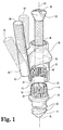
- FIG. 1 is a perspective view of an embodiment using an angulated headpiece having a connector adapted to engage a plate-like longitudinal member and with portions removed to reveal aspects of the invention;
- FIG. 2 is a perspective view of the embodiment shown in FIG. 1 which is designed to work with a rod-like longitudinal member and has portions removed to reveal aspects of the invention;
- FIG. 3 is a perspective view of an embodiment having a translational headpiece consisting of a plurality of lateral length sections;
- FIG. 4 is a perspective view of an embodiment having an angulated translational headpiece consisting of a plurality of angular and lateral length configurations;
- FIG. 5 is a posterior view of a spinal section in which an apparatus constructed in accordance with the present invention has been implanted
- FIG. 6 is an enlarged view, partly in section taken generally along the line 6 — 6 of FIG. 5, illustrating an embodiment threaded into a spinal element and overcoming angular misalignment of the fastener;
- FIG. 7 is an enlarged view, partly in section taken generally along the line 7 — 7 of FIG. 5, illustrating an embodiment threaded into a spinal element and overcoming lateral misalignment of the fastener;
- FIG. 8 is an enlarged view, partly in section taken generally along the line 8 — 8 of FIG. 5, illustrating an embodiment threaded into a spinal element and overcoming both angular and lateral misalignment of the fastener.
- FIG. 9 is a partial side cross-sectional view of a system of this invention.
- FIG. 10 is a perspective view of a spinal plate.
- FIG. 11 is a perspective view of another spinal plate.
- FIG. 12 is a side elevational view of a bone bolt.
- FIG. 13 is an elevational view of a bracket of this invention.
- FIG. 14 is a side elevational view of the bracket.
- FIG. 15 is a top elevational view of the bracket.
- FIG. 16 is an elevational view of another embodiment of this invention.
- FIG. 17 is an elevational view of another embodiment of this invention.
- FIG. 18 is a side elevational view of a bracket and a bone fastener.
- the modular pedicle screw system includes a pedicle screw or fastener 10 ; a headpiece 30 which is adapted to engage fastener 10 ; and, a locking element 50 which mechanically affixes fastener 10 to headpiece 30 .
- Fastener 10 also includes a threaded lower portion 12 for engaging a spinal element and an upper portion 14 which is adapted to allow for the mechanical affixment of fastener 10 to headpiece 30 .
- One suitable configuration for upper portion 14 that provides rotational and lateral stability is a frusto-conical shape 15 having fluted edges 15 on its outer surface as shown in FIGS. 1 and 2.
- Upper portion 14 may also be configured as a cylinder, square, hex, or in other shapes persons of ordinary skill would recognize.
- Fastener 10 further includes a bore 18 which allows fastener 10 to be cannulated during insertion.
- the diameter of bore 18 is increased near upper portion 14 to form an internal threaded portion 20 for receiving locking element 50 .
- Bore 18 of fastener 14 may also terminate in a hex-shaped recess 23 which provides a surface that can engage a suitable insertion tool (not shown).
- a shoulder 24 may also be provided which acts as a stop that limits the depth fastener 10 can be inserted.
- headpiece 30 includes a neck portion 32 having cylindrical aperture 34 with engagement surface 38 .
- Engagement surface 38 is dimensioned so as to allow head 52 of locking element 50 to form a secure fit with upper surface 38 when inserted.
- Neck 32 further includes a recess 40 which is adapted to mate with upper portion 14 of fastener 10 .
- recess 40 would have a mating fluted surface 42 and would be configured to mate with the frusto-conical shape 15 .
- Recess 40 may also have other configurations designed to mate with the other shapes described above.
- headpiece 30 there are a number of variations of headpiece 30 which are built upon the basic structure of headpiece 30 as described above.
- One is an angulated headpiece 60 (also shown as headpiece 30 of FIGS. 1 and 2 ), which includes a projection 62 that extends out of neck 32 as shown in FIG. 1 .
- Projection 62 terminates in a connector which can be either a threaded shank 64 (as shown in FIG. 1) or a rod connector 66 having an engagement aperture 65 , a threaded bore 68 and a locking screw 69 (as shown in FIG. 2 ), which are, in turn, adapted to secure a longitudinal member such as plate of design similar to that disclosed in the Small, et al. patent or a rod 62 of a design similar to that disclosed in the Asher, et al. patent, respectively.
- a longitudinal member such as plate of design similar to that disclosed in the Small, et al. patent or a rod 62 of a design similar to that disclosed in the Asher,
- headpiece variations which will be described below, may also terminate in these connectors, but persons of ordinary skill in the art would also recognize that the headpieces may be adapted to work with other types of longitudinal support members as well. Since one of the purposes of the invention is to overcome angular misalignment, projection 62 of the angulated headpiece 60 is angled with respect to centerline 63 of headpiece 60 as shown in FIG. 1 . The degrees of angulation of projection 62 should vary but should include angulations in the range of about 5° to 45°.
- FIG. 3 illustrates translational headpiece 70 .
- Translational headpiece 70 includes lateral section 72 which extends outwardly from centerline 77 of headpiece 70 and terminates with a connector 73 as described above.
- the length (LL′, L′′) of section 72 should vary and include typical lengths ranging from about 5 millimeters to 3 centimeters.
- another headpiece embodiment is an angulated translational headpiece 80 , which is a combination of the previously described headpiece embodiments.
- Headpiece 80 includes lateral section 82 which extends outwardly from centerline 81 of headpiece 80 .
- section 82 is also angulated with respect to a horizontal axis shown as line 89 .
- the degrees of angulation ( ⁇ ) should vary and may include angulations in the range of about 2° to 45°.
- the lengths (LL′, L′′) of section 82 should also vary as described above.
- fastener 10 will first be secured to a spinal element 90 by a suitable insertion tool which may be a hex-shaped wrench or a wrench having a bore designed to mate with upper portion 14 .
- a suitable insertion tool which may be a hex-shaped wrench or a wrench having a bore designed to mate with upper portion 14 .
- the clinician will then select one of the angulated headpieces 60 which best compensates for the angular misalignment, if any, and returns the threads shank or rod connector to a position where it is once again in longitudinal alignment wit the longitudinal member 91 and other fasteners.
- the headpiece and fastener will then be secured together by set screw 50 , and ultimately, a longitudinal member will be securingly retained by a connector as previously described.
- fastener 10 will first be secured to a spinal element 90 .
- the clinician will then select one of the translational headpieces 70 which best compensates for the misalignment and returns connector 73 to a position of proper alignment for securing a longitudinal member 91 .
- an potential interference from spinal retractors, other elements of the spine, or the other screws which have already been implanted can be eliminated.
- the clinician can use the present invention in areas which may not be accessible to other offset bolts currently available.
- an angulated translational headpiece 80 is used. Again, fastener 10 is first inserted into spinal element 90 . The clinician then selects the appropriate headpiece with the correct lateral length and angular deflection which will compensate for the misalingment as shown in FIGS. 5 and 8.
- the present invention also provides spinal fixation systems including a spinal plate, a bone fastener and an offset connector or bracket for relating the plate to the fastener.
- the bracket of this invention can also be incorporated into known plate and screw systems such as the DYNALOK® Spinal System and the Danek® Plate and Screw System available from Danek Medical, Inc. 1800 Pyramid Place, Memphis, Tenn. 38132 (800-93-DANEK).
- a spinal fixation system 100 for maintaining vertebrae in a desired relationship is provided as shown in FIG. 9 .
- the system 100 includes spinal plate 101 shown in cross-section, a bracket 120 , a bone screw or bolt 110 and a pair of internally threaded fasteners, such as nuts 150 .
- the plate element 101 is preferably a substantially rigid, elongated spinal plate having a length for spanning the vertebrae.
- the plate 101 includes a bottom side 102 for facing the vertebrae and an opposite top side 103 extending generally parallel to the bottom side 102 .
- An elongated slot 104 is defined between the bottom side 102 and the top side 103 .
- the slot 104 preferably extends substantially along the length of the plate 101 and has a lower edge 105 at the intersection of the slot 104 and the bottom surface 102 and an upper edge 106 at the intersection of the slot 104 and the top surface 103 .
- the plate 101 also preferably includes a number of scallops 107 formed at the lower edge 105 and the upper edge 106 of the slot 104 . This is similar to the bone plate of the DANEK® Plate and Screw System marketed by Danek Medical, Inc.
- This plate 101 ′ includes a first set of scallops 107 a and a second set of scallops 107 b .
- Each of the sets of scallops 107 a , 107 b are formed in both the upper 106 ′ and lower 105 ′ edges.
- the first set of scallops 107 a has a spherical radius that is different from the second set 107 b as described in U.S. Pat. No. 5,209,751 to Farris et al., the disclosure of which is incorporated herein by reference.
- a similar plate is marketed by Danek Medical, Inc. for its DYNALOK® Spinal System.
- the system also includes a bone fastener such as a bone screw or a bone bolt.
- a bone fastener such as a bone screw or a bone bolt.
- double hex screws such as marketed by Danek Medical, Inc. are used.
- the bone fastener is a double threaded bolt such as the Danek Medical DYNALOK® cannulated bolt.
- a bone bolt 110 has an elongated shaft 111 having a first threaded portion 112 , a second threaded portion 113 and an intermediate portion 114 between the first 112 and second 113 threaded portions.
- the second threaded portion 113 includes a number of threads 115 adapted to engage the bone of the vertebra.
- the intermediate portion 114 of this embodiment has an integral rigid upper arcuate surface 116 facing toward the first threaded portion 112 .
- the bolt 110 is cannulated to include a bore 117 extending through the entire length of the bolt 110 .
- the bolt 110 is also provided with an insertion tool cavity 118 in an end of the first portion 112 .
- the cavity 118 is hexagonal in configuration for engaging an insertion tool.
- the system 100 can include a bracket 120 for connecting the plate 101 to the bone.
- the bracket 120 includes a headpiece 125 , a connector 135 laterally offset from the headpiece 125 and a lateral projection 145 extending outwardly from the headpiece 125 and attaching the headpiece 125 to the connector 135 .
- Connector 135 includes a post 136 which is engageable to an aperture in the longitudinal member, such as the slot 104 ′ shown in FIG. 11 .
- the headpiece 125 defines bore 126 for receiving a bone fastener such as bolt 110 .
- the connector 135 is configured to mate with an aperture in a spinal plate such as the ones depicted in FIGS. 10 and 11 herein.
- the post 136 of the connector 135 includes a first longitudinal member mating surface 137 for mating with an aperture such as the slot 104 or 104 ′ in the plates shown in FIGS. 10 and 11.
- the mating surface 137 is sized to span the plate aperture and provide a substantial surface for stably supporting the bottom side 102 of the plate.
- the post 136 defines a vertical axis V which is perpendicular to a horizontal axis H defined by the connector 135 .
- the connector 135 also includes a second longitudinal member mating surface 138 which is concentric with the post 136 .
- the second mating surface 138 is preferably convex for mating engagement with a concave surface such as scallops 107 of the longitudinal member or plate 101 .
- the post 136 of the connector 135 also includes a fastener engaging surface 139 .
- the fastener engaging surface 139 is provided with threads 139 a for engaging an internally threaded fastener such as nut 150 .
- the post 136 may also be provided with an aperture for receiving a driving tool such as an internal hex 141 .
- the headpiece 125 of the bracket 120 is provided to engage a bone fastener offset from the engagement of the bracket 120 with a spinal plate.
- the headpiece 125 includes a first face 127 and an opposite second face 128 .
- a bore 126 defined to extend between the first face 127 and the second face 128 .
- the headpiece 125 defines a bore axis B through the bore 126 .
- the headpiece 125 further includes angulation means for variably angulating the bone fastener relative to the bore axis B.
- the angulation means includes a first concave depression 129 defined in the first face 127 and concentric with the bore 126 .
- the second concave depression (not shown) is preferably defined in the second face 128 also concentric with the bore 126 .
- the angulation means includes first and second sets of nested concave depressions. The depressions of the first set 131 include the first concave depression 129 and another corresponding concave depression (not shown) on the opposite side 128 .
- the second set of concave depressions includes a concave depression 132 which is concentric with the bore 126 and another corresponding concave depression (not shown) on the opposite face 128 .
- the first set 131 has a spherical radius R 1 that is different from the radius R 2 of the second set 132 .
- the second set 132 includes a second concave depression 133 defined in the first face 137 and a corresponding concave depression (not shown) on the opposite side 128 .
- the angulation means in connection with the arcuate surface 116 of the bolt 110 allows the fastener 110 to angulate relative to the axis of the bore B at a particular angle ⁇ .
- a fastener is preferably provided which will engage the first portion 112 and one of the concave depressions 129 or 133 .
- the lateral projection 145 of the bracket 120 extends outwardly from the headpiece 125 and attaches headpiece 125 to connector 135 .
- the lateral projection 145 also provides translational and angular adjustment.
- the lateral projection 145 may have any suitable length so that the bracket 120 has a desired length L between the vertical axis V of the post and the bore axis B.
- the lateral projection 145 is parallel with the horizontal axis H at 90° from the vertical axis V.
- the lateral projection 145 is angulated relative to the horizontal axis H at an angle in the range of about 2° to about 45°. Two such embodiments are depicted in FIGS. 16 and 17.
- the angulation angle ⁇ 1 as related to the horizontal axis H 1 is about 15°
- the angulation angle ⁇ 2 relating to axis H 2 is about 30°.
- the angulation angle ⁇ of the lateral projection 145 when the angulation angle ⁇ of the lateral projection 145 is 0° from the vertical axis V, the bore axis B and the vertical axis v will be parallel. However, as shown in FIGS. 16 and 17 when the angulation angle ⁇ 1 or ⁇ 2 is anything other than 0° or 180° the vertical axis V and the bore axis B will no longer be parallel and will converge at some point.
- the combination of the angulation of the lateral projection 145 , the variation in the distance L between the vertical axis and the bore axis along with the angulation means of the bore 126 of the headpiece 125 offer superior compensation for both translational and angular misalignment of bone fasteners relative to spinal plates.
- the differing lengths of the lateral projections 145 compensate for translational misalignment of bone bolts relative to spinal plates.
- the angulation of the lateral projection 145 compensates for angular misalignment of
- the invention also contemplates fasteners for both the threaded post 136 of the connector 135 and the first portion 112 of the bone bolt 110 .
- the fastener is an internally threaded nut 150 for mating engagement with threads 119 of the first portion 112 of the bolt and the threaded portion 139 of the post 136 of the connector 135 .
- the nut 150 is provided with a rigid lower arcuate surface 157 which is substantially complementary to the concave depressions 129 and 133 and is received within the concave depressions when the nut 150 is tightened down along the first threaded portion 112 .
- the arcuate surface 157 will also preferably be complimentary with scallops 107 in the plate so that the nut 150 will be received within the scallops when the nut 150 is engaged to the threaded post and tightened down on the plate and within the scallops.
- the invention also preferably includes various kits for spinal surgery.
- One of the kits includes a plurality of brackets, bone bolts and nuts.
- Another kit of this invention provides a plurality of brackets to be used with existing spinal systems such as the DYNALOK® or the DANEK® Plate System of Danek Medical, Inc.
- the surgeon will be provided with many options for fitting a spinal device such as a plate to a fixation member such as bone screw or a bone bolt.
- a fixation member such as bone screw or a bone bolt.
- the surgeon can compensate for any translational and angular misalignment of the bone fasteners relative to the plate by simply using an appropriate bracket.
Landscapes
- Health & Medical Sciences (AREA)
- Orthopedic Medicine & Surgery (AREA)
- Life Sciences & Earth Sciences (AREA)
- Neurology (AREA)
- Surgery (AREA)
- Heart & Thoracic Surgery (AREA)
- Engineering & Computer Science (AREA)
- Biomedical Technology (AREA)
- Nuclear Medicine, Radiotherapy & Molecular Imaging (AREA)
- Medical Informatics (AREA)
- Molecular Biology (AREA)
- Animal Behavior & Ethology (AREA)
- General Health & Medical Sciences (AREA)
- Public Health (AREA)
- Veterinary Medicine (AREA)
- Prostheses (AREA)
- Surgical Instruments (AREA)
Abstract
Description
Claims (7)
Priority Applications (1)
| Application Number | Priority Date | Filing Date | Title |
|---|---|---|---|
| US09/718,915 US6379357B1 (en) | 1994-10-25 | 2000-11-22 | Modular spinal system |
Applications Claiming Priority (4)
| Application Number | Priority Date | Filing Date | Title |
|---|---|---|---|
| US32883394A | 1994-10-25 | 1994-10-25 | |
| US08/707,025 US6004322A (en) | 1994-10-25 | 1996-09-10 | Modular pedicle screw system |
| US08/798,855 US6176861B1 (en) | 1994-10-25 | 1997-02-12 | Modular spinal system |
| US09/718,915 US6379357B1 (en) | 1994-10-25 | 2000-11-22 | Modular spinal system |
Related Parent Applications (1)
| Application Number | Title | Priority Date | Filing Date |
|---|---|---|---|
| US08/798,855 Continuation US6176861B1 (en) | 1994-10-25 | 1997-02-12 | Modular spinal system |
Publications (1)
| Publication Number | Publication Date |
|---|---|
| US6379357B1 true US6379357B1 (en) | 2002-04-30 |
Family
ID=26986531
Family Applications (2)
| Application Number | Title | Priority Date | Filing Date |
|---|---|---|---|
| US08/798,855 Expired - Lifetime US6176861B1 (en) | 1994-10-25 | 1997-02-12 | Modular spinal system |
| US09/718,915 Expired - Lifetime US6379357B1 (en) | 1994-10-25 | 2000-11-22 | Modular spinal system |
Family Applications Before (1)
| Application Number | Title | Priority Date | Filing Date |
|---|---|---|---|
| US08/798,855 Expired - Lifetime US6176861B1 (en) | 1994-10-25 | 1997-02-12 | Modular spinal system |
Country Status (1)
| Country | Link |
|---|---|
| US (2) | US6176861B1 (en) |
Cited By (66)
| Publication number | Priority date | Publication date | Assignee | Title |
|---|---|---|---|---|
| US6676661B1 (en) * | 1999-07-23 | 2004-01-13 | Antonio Martin Benlloch | Multiaxial connector for spinal implant |
| US20040210216A1 (en) * | 2003-04-17 | 2004-10-21 | Farris Robert A | Spinal fixation system and method |
| US20050038429A1 (en) * | 2001-12-09 | 2005-02-17 | Elsebaie Hazem Bayoumi | Articulated vertebral fixing |
| US20050049595A1 (en) * | 2003-09-03 | 2005-03-03 | Suh Sean S. | Track-plate carriage system |
| US20050203516A1 (en) * | 2004-03-03 | 2005-09-15 | Biedermann Motech Gmbh | Anchoring element and stabilization device for the dynamic stabilization of vertebrae or bones using such anchoring elements |
| US20050216001A1 (en) * | 2004-03-23 | 2005-09-29 | Stryker Spine | Sphere and bone plate |
| US20050277923A1 (en) * | 2004-06-09 | 2005-12-15 | Sweeney Patrick J | Spinal fixation system |
| US20050277931A1 (en) * | 2004-06-09 | 2005-12-15 | Spinal Generations, Llc | Spinal fixation system |
| US20060155277A1 (en) * | 2002-03-21 | 2006-07-13 | Peter Metz-Stavenhagen | Anchoring element for securing a rod of a device for adjusting a human or animal vertrebal column on a vertreba |
| US20060200131A1 (en) * | 2005-03-04 | 2006-09-07 | Depuy Spine Sarl | Constrained motion bone screw assembly |
| US20060229615A1 (en) * | 2005-02-18 | 2006-10-12 | Abdou M S | Devices and methods for dynamic fixation of skeletal structure |
| US20070010817A1 (en) * | 2005-07-06 | 2007-01-11 | Stryker Spine S.A. | Multi-axial bone plate system |
| US20070049932A1 (en) * | 2005-08-23 | 2007-03-01 | Aesculap Ag & Co. Kg | Rod to rod connector |
| US20070093824A1 (en) * | 2005-09-22 | 2007-04-26 | Hestad Hugh D | Pedicle fixation rod alignment system |
| US20070173833A1 (en) * | 2006-01-10 | 2007-07-26 | Life Spine, Llc | Pedicle screw constructs and spinal rod attachment assemblies |
| US20080021473A1 (en) * | 2004-01-13 | 2008-01-24 | Life Spine Llc | Pedicle screw constructs for spine fixation systetms |
| WO2008036578A2 (en) * | 2006-09-18 | 2008-03-27 | Warsaw Orthopedic, Inc | Orthopedic plate system |
| US20080097447A1 (en) * | 2006-09-18 | 2008-04-24 | Warsaw Orthopedic, Inc. | Orthopedic plate system |
| US20080177323A1 (en) * | 2006-10-18 | 2008-07-24 | Null William B | Orthopedic revision connector |
| US20080177315A1 (en) * | 2006-12-20 | 2008-07-24 | Aesculap Ii, Inc. | Rod to Rod Connector |
| US20090228053A1 (en) * | 2008-03-10 | 2009-09-10 | Eric Kolb | Derotation instrument with reduction functionality |
| US20090312804A1 (en) * | 2008-06-17 | 2009-12-17 | Thomas Gamache | Adjustable implant assembly |
| US20100076448A1 (en) * | 2003-12-29 | 2010-03-25 | Abdou M Samy | Plating system for bone fixation and method of implantation |
| US7736380B2 (en) | 2004-12-21 | 2010-06-15 | Rhausler, Inc. | Cervical plate system |
| US7766911B1 (en) | 2002-07-05 | 2010-08-03 | Theken Spine, Llc | Fixed and variable locking fixation assembly |
| US20100198273A1 (en) * | 2005-10-21 | 2010-08-05 | Kwak Seungkyu Daniel | Adjustable bone screw assembly |
| US7951168B2 (en) | 2005-03-04 | 2011-05-31 | Depuy Spine, Inc. | Instruments and methods for manipulating vertebra |
| US8021398B2 (en) | 2004-06-09 | 2011-09-20 | Life Spine, Inc. | Spinal fixation system |
| US20120010658A1 (en) * | 2010-07-08 | 2012-01-12 | X-Spine Systems, Inc. | Spinal stabilization system utilizing screw and external facet and/or lamina fixation |
| US20120109197A1 (en) * | 2004-08-03 | 2012-05-03 | Albany Medical College | Facet device and method |
| KR101194334B1 (en) | 2004-03-03 | 2012-10-24 | 비이더만 모테크 게엠베하 & 코. 카게 | Anchoring element and stabilization device for the dynamic stabilization of vertebrae or bones using such anchoring elements |
| US8348952B2 (en) | 2006-01-26 | 2013-01-08 | Depuy International Ltd. | System and method for cooling a spinal correction device comprising a shape memory material for corrective spinal surgery |
| US20130023935A1 (en) * | 2008-10-10 | 2013-01-24 | Khiem Pham | Uniplanar Screw |
| US8388660B1 (en) | 2006-08-01 | 2013-03-05 | Samy Abdou | Devices and methods for superior fixation of orthopedic devices onto the vertebral column |
| US8414614B2 (en) | 2005-10-22 | 2013-04-09 | Depuy International Ltd | Implant kit for supporting a spinal column |
| US8425563B2 (en) | 2006-01-13 | 2013-04-23 | Depuy International Ltd. | Spinal rod support kit |
| US8430914B2 (en) | 2007-10-24 | 2013-04-30 | Depuy Spine, Inc. | Assembly for orthopaedic surgery |
| US8617216B2 (en) | 2010-04-05 | 2013-12-31 | David L. Brumfield | Fully-adjustable bone fixation device |
| US8709015B2 (en) | 2008-03-10 | 2014-04-29 | DePuy Synthes Products, LLC | Bilateral vertebral body derotation system |
| US8771319B2 (en) | 2012-04-16 | 2014-07-08 | Aesculap Implant Systems, Llc | Rod to rod cross connector |
| US8828056B2 (en) | 2012-04-16 | 2014-09-09 | Aesculap Implant Systems, Llc | Rod to rod cross connector |
| US8992579B1 (en) | 2011-03-08 | 2015-03-31 | Nuvasive, Inc. | Lateral fixation constructs and related methods |
| US9005249B2 (en) | 2011-07-11 | 2015-04-14 | Life Spine, Inc. | Spinal rod connector assembly |
| US9060815B1 (en) | 2012-03-08 | 2015-06-23 | Nuvasive, Inc. | Systems and methods for performing spine surgery |
| US9101416B2 (en) | 2003-01-24 | 2015-08-11 | DePuy Synthes Products, Inc. | Spinal rod approximator |
| US9113959B2 (en) | 2011-11-16 | 2015-08-25 | K2M, Inc. | Spinal correction and secondary stabilization |
| US9271743B2 (en) | 2012-08-09 | 2016-03-01 | Wilson Theophilo Asfora | System for joint fusion |
| US9408646B2 (en) | 2003-09-03 | 2016-08-09 | DePuy Synthes Products, Inc. | Bone plate with captive clips |
| US20160341245A1 (en) * | 2014-12-05 | 2016-11-24 | Black & Decker Inc. | Swivel hanger system |
| US9517089B1 (en) | 2013-10-08 | 2016-12-13 | Nuvasive, Inc. | Bone anchor with offset rod connector |
| US9743959B2 (en) * | 2013-03-14 | 2017-08-29 | Atlas Spine, Inc. | Low profile spinal fixation system |
| US20180283443A1 (en) * | 2014-12-05 | 2018-10-04 | Black & Decker Inc. | Swivel hanger |
| US10342581B2 (en) | 2011-11-16 | 2019-07-09 | K2M, Inc. | System and method for spinal correction |
| US10543107B2 (en) | 2009-12-07 | 2020-01-28 | Samy Abdou | Devices and methods for minimally invasive spinal stabilization and instrumentation |
| US10548740B1 (en) | 2016-10-25 | 2020-02-04 | Samy Abdou | Devices and methods for vertebral bone realignment |
| US10575961B1 (en) | 2011-09-23 | 2020-03-03 | Samy Abdou | Spinal fixation devices and methods of use |
| US10695105B2 (en) | 2012-08-28 | 2020-06-30 | Samy Abdou | Spinal fixation devices and methods of use |
| US10702311B2 (en) | 2011-11-16 | 2020-07-07 | K2M, Inc. | Spinal correction and secondary stabilization |
| US10857003B1 (en) | 2015-10-14 | 2020-12-08 | Samy Abdou | Devices and methods for vertebral stabilization |
| US10918498B2 (en) | 2004-11-24 | 2021-02-16 | Samy Abdou | Devices and methods for inter-vertebral orthopedic device placement |
| US10973648B1 (en) | 2016-10-25 | 2021-04-13 | Samy Abdou | Devices and methods for vertebral bone realignment |
| US11006982B2 (en) | 2012-02-22 | 2021-05-18 | Samy Abdou | Spinous process fixation devices and methods of use |
| US11173040B2 (en) | 2012-10-22 | 2021-11-16 | Cogent Spine, LLC | Devices and methods for spinal stabilization and instrumentation |
| US11179248B2 (en) | 2018-10-02 | 2021-11-23 | Samy Abdou | Devices and methods for spinal implantation |
| AU2017210491B2 (en) * | 2016-08-04 | 2022-10-13 | Black & Decker Inc. | Swivel hanger system |
| US11992423B2 (en) | 2021-08-23 | 2024-05-28 | Samy Abdou | Devices and methods for inter-vertebral orthopedic device placement |
Families Citing this family (59)
| Publication number | Priority date | Publication date | Assignee | Title |
|---|---|---|---|---|
| US6235033B1 (en) * | 2000-04-19 | 2001-05-22 | Synthes (Usa) | Bone fixation assembly |
| AU8047601A (en) * | 2000-06-30 | 2002-01-14 | Stephen Ritland | Polyaxial connection device and method |
| US20050080486A1 (en) | 2000-11-29 | 2005-04-14 | Fallin T. Wade | Facet joint replacement |
| US6579319B2 (en) * | 2000-11-29 | 2003-06-17 | Medicinelodge, Inc. | Facet joint replacement |
| US6565605B2 (en) | 2000-12-13 | 2003-05-20 | Medicinelodge, Inc. | Multiple facet joint replacement |
| US7090698B2 (en) * | 2001-03-02 | 2006-08-15 | Facet Solutions | Method and apparatus for spine joint replacement |
| EP1429671B1 (en) * | 2001-09-28 | 2011-01-19 | Stephen Ritland | Connection rod for screw or hook polyaxial system |
| US6899714B2 (en) * | 2001-10-03 | 2005-05-31 | Vaughan Medical Technologies, Inc. | Vertebral stabilization assembly and method |
| NZ533664A (en) | 2001-12-24 | 2005-01-28 | Synthes Ag | Device for performing osteosynthesis |
| US6682530B2 (en) * | 2002-01-14 | 2004-01-27 | Robert A Dixon | Dynamized vertebral stabilizer using an outrigger implant |
| US7763047B2 (en) * | 2002-02-20 | 2010-07-27 | Stephen Ritland | Pedicle screw connector apparatus and method |
| US6966910B2 (en) * | 2002-04-05 | 2005-11-22 | Stephen Ritland | Dynamic fixation device and method of use |
| EP2457528A1 (en) | 2002-05-08 | 2012-05-30 | Stephen Ritland | Dynamic fixation device and method of use |
| US20060129151A1 (en) * | 2002-08-28 | 2006-06-15 | Allen C W | Systems and methods for securing fractures using plates and cable clamps |
| US7179260B2 (en) * | 2003-09-29 | 2007-02-20 | Smith & Nephew, Inc. | Bone plates and bone plate assemblies |
| US7250054B2 (en) * | 2002-08-28 | 2007-07-31 | Smith & Nephew, Inc. | Systems, methods, and apparatuses for clamping and reclamping an orthopedic surgical cable |
| CA2516791C (en) * | 2003-02-25 | 2011-12-13 | Stephen Ritland | Adjustable rod and connector device and method of use |
| US8262571B2 (en) * | 2003-05-22 | 2012-09-11 | Stephen Ritland | Intermuscular guide for retractor insertion and method of use |
| US8105367B2 (en) | 2003-09-29 | 2012-01-31 | Smith & Nephew, Inc. | Bone plate and bone plate assemblies including polyaxial fasteners |
| US8926700B2 (en) * | 2003-12-10 | 2015-01-06 | Gmedelware 2 LLC | Spinal facet joint implant |
| US8333789B2 (en) * | 2007-01-10 | 2012-12-18 | Gmedelaware 2 Llc | Facet joint replacement |
| US7993373B2 (en) | 2005-02-22 | 2011-08-09 | Hoy Robert W | Polyaxial orthopedic fastening apparatus |
| US9492203B2 (en) * | 2004-02-17 | 2016-11-15 | Globus Medical, Inc. | Facet joint replacement instruments and methods |
| US8562649B2 (en) | 2004-02-17 | 2013-10-22 | Gmedelaware 2 Llc | System and method for multiple level facet joint arthroplasty and fusion |
| US8764801B2 (en) * | 2005-03-28 | 2014-07-01 | Gmedelaware 2 Llc | Facet joint implant crosslinking apparatus and method |
| US7588578B2 (en) * | 2004-06-02 | 2009-09-15 | Facet Solutions, Inc | Surgical measurement systems and methods |
| US7658753B2 (en) * | 2004-08-03 | 2010-02-09 | K Spine, Inc. | Device and method for correcting a spinal deformity |
| WO2006029274A1 (en) * | 2004-09-07 | 2006-03-16 | Smith & Nephew, Inc. | Minimal thickness bone plate locking mechanism |
| US7455639B2 (en) * | 2004-09-20 | 2008-11-25 | Stephen Ritland | Opposing parallel bladed retractor and method of use |
| US8469966B2 (en) * | 2004-09-23 | 2013-06-25 | Smith & Nephew, Inc. | Systems, methods, and apparatuses for tensioning an orthopedic surgical cable |
| US7722647B1 (en) | 2005-03-14 | 2010-05-25 | Facet Solutions, Inc. | Apparatus and method for posterior vertebral stabilization |
| US7585312B2 (en) * | 2005-04-29 | 2009-09-08 | Warsaw Orthopedic, Inc. | Spinal stabilization apparatus and method |
| US7776074B2 (en) * | 2005-06-08 | 2010-08-17 | Robert S. Bray, Jr. | Procedure for aligning and stabilizing bone elements |
| AU2006269900A1 (en) | 2005-07-19 | 2007-01-25 | Stephen Ritland | Rod extension for extending fusion construct |
| US8382807B2 (en) | 2005-07-25 | 2013-02-26 | Smith & Nephew, Inc. | Systems and methods for using polyaxial plates |
| JP5270339B2 (en) | 2005-07-25 | 2013-08-21 | スミス アンド ネフュー インコーポレーテッド | System and method for using a multi-axis plate |
| FR2894129B1 (en) * | 2005-12-07 | 2008-08-22 | Alain Tornier | DEVICE FOR STABILIZING THE RACHIS |
| US7959564B2 (en) | 2006-07-08 | 2011-06-14 | Stephen Ritland | Pedicle seeker and retractor, and methods of use |
| AU2008204784A1 (en) * | 2007-01-10 | 2008-07-17 | Facet Solutions, Inc. | Taper-locking fixation system |
| CA2689965A1 (en) | 2007-06-06 | 2008-12-18 | Kspine, Inc. | Medical device and method to correct deformity |
| US20090043311A1 (en) * | 2007-08-07 | 2009-02-12 | Koros Tibor B | Offset distraction device and method of use |
| US20090076550A1 (en) * | 2007-09-18 | 2009-03-19 | Ortho Development Corporation | Spinal fixation system connectors |
| US8425608B2 (en) * | 2008-01-18 | 2013-04-23 | Warsaw Orthopedic, Inc. | Lordotic expanding vertebral body spacer |
| US7857835B2 (en) * | 2008-02-22 | 2010-12-28 | Depuy Spine, Inc. | Method and system for trans-lamina spinal fixation |
| ES2387512T3 (en) * | 2008-09-05 | 2012-09-25 | Biedermann Technologies Gmbh & Co. Kg | Bone stabilization device, in particular for the spine |
| US8828058B2 (en) | 2008-11-11 | 2014-09-09 | Kspine, Inc. | Growth directed vertebral fixation system with distractible connector(s) and apical control |
| US8357182B2 (en) | 2009-03-26 | 2013-01-22 | Kspine, Inc. | Alignment system with longitudinal support features |
| US20100318129A1 (en) * | 2009-06-16 | 2010-12-16 | Kspine, Inc. | Deformity alignment system with reactive force balancing |
| US9168071B2 (en) | 2009-09-15 | 2015-10-27 | K2M, Inc. | Growth modulation system |
| WO2011094330A1 (en) | 2010-01-26 | 2011-08-04 | Touchtunes Music Corporation | Digital jukebox device with improved user interfaces, and associated methods |
| AU2012261983B2 (en) | 2011-06-03 | 2015-10-08 | K2M, Inc. | Spinal correction system actuators |
| JP2014522673A (en) | 2011-06-15 | 2014-09-08 | スミス アンド ネフュー インコーポレーテッド | Locking implant with variable angle |
| US9468468B2 (en) | 2011-11-16 | 2016-10-18 | K2M, Inc. | Transverse connector for spinal stabilization system |
| US9468469B2 (en) | 2011-11-16 | 2016-10-18 | K2M, Inc. | Transverse coupler adjuster spinal correction systems and methods |
| US9468471B2 (en) | 2013-09-17 | 2016-10-18 | K2M, Inc. | Transverse coupler adjuster spinal correction systems and methods |
| US11452612B2 (en) | 2014-10-09 | 2022-09-27 | Warsaw Orthopedic, Inc. | Spinal implant system and method |
| FR3034979B1 (en) * | 2015-04-17 | 2021-08-27 | Implanet | DEVICE, SYSTEM AND METHOD FOR FIXING A SPINAL VERTEBRA ON A ROD. |
| US10993750B2 (en) | 2015-09-18 | 2021-05-04 | Smith & Nephew, Inc. | Bone plate |
| US10835292B2 (en) * | 2018-06-13 | 2020-11-17 | Nuvasive, Inc. | Rib fixation device and related methods |
Citations (37)
| Publication number | Priority date | Publication date | Assignee | Title |
|---|---|---|---|---|
| US2439995A (en) | 1944-04-11 | 1948-04-20 | Orville W Thrailkill | Securing device |
| US2627855A (en) | 1950-04-07 | 1953-02-10 | James W Price | Fracture nail and bone plate |
| FR1136123A (en) | 1955-11-14 | 1957-05-09 | Chevalier Et Fils E | Osteosynthesis apparatus |
| FR1293395A (en) | 1961-06-27 | 1962-05-11 | Surgical apparatus | |
| GB2090745A (en) | 1981-01-09 | 1982-07-21 | Howmedica Uk Ltd | Device for treating trochanteric fracture |
| US4569338A (en) | 1984-02-09 | 1986-02-11 | Edwards Charles C | Sacral fixation device |
| US4648388A (en) | 1985-11-01 | 1987-03-10 | Acromed Corporation | Apparatus and method for maintaining vertebrae in a desired relationship |
| FR2615095A1 (en) | 1987-05-15 | 1988-11-18 | Fabrication Materiel Orthopedi | Osteosynthesis instrumentation for the correction of lumbar scoliosis through the posterior |
| US4854311A (en) | 1986-01-09 | 1989-08-08 | Acro Med Corporation | Bone screw |
| US4887585A (en) | 1988-05-20 | 1989-12-19 | Nutt David H | Method and apparatus for cutting taps in sewer lines |
| US4946458A (en) | 1986-04-25 | 1990-08-07 | Harms Juergen | Pedicle screw |
| US4987892A (en) | 1989-04-04 | 1991-01-29 | Krag Martin H | Spinal fixation device |
| US5024213A (en) | 1989-02-08 | 1991-06-18 | Acromed Corporation | Connector for a corrective device |
| US5047029A (en) | 1988-06-10 | 1991-09-10 | Synthes (U.S.A.) | Clamp and system for internal fixation |
| US5053034A (en) | 1990-08-03 | 1991-10-01 | Sven Olerud | Spinal joint |
| US5084049A (en) | 1989-02-08 | 1992-01-28 | Acromed Corporation | Transverse connector for spinal column corrective devices |
| EP0468264A1 (en) | 1990-07-24 | 1992-01-29 | Acromed Corporation | Spinal column retaining method and apparatus |
| US5113685A (en) | 1991-01-28 | 1992-05-19 | Acromed Corporation | Apparatus for contouring spine plates and/or rods |
| US5129899A (en) | 1991-03-27 | 1992-07-14 | Smith & Nephew Richards Inc. | Bone fixation apparatus |
| FR2671966A3 (en) | 1991-01-24 | 1992-07-31 | Hit Medica Srl | Device for reducing factures |
| US5196014A (en) | 1991-09-23 | 1993-03-23 | Lin Chih I | Vertebral locking and retrieving system |
| US5217461A (en) | 1992-02-20 | 1993-06-08 | Acromed Corporation | Apparatus for maintaining vertebrae in a desired spatial relationship |
| EP0553424A1 (en) | 1992-01-30 | 1993-08-04 | Acromed Corporation | Spinal column retaining apparatus |
| US5242443A (en) | 1991-08-15 | 1993-09-07 | Smith & Nephew Dyonics, Inc. | Percutaneous fixation of vertebrae |
| US5257994A (en) | 1991-09-23 | 1993-11-02 | Lin Chih I | Vertebral locking and retrieving system |
| US5261909A (en) | 1992-02-18 | 1993-11-16 | Danek Medical, Inc. | Variable angle screw for spinal implant system |
| US5275601A (en) | 1991-09-03 | 1994-01-04 | Synthes (U.S.A) | Self-locking resorbable screws and plates for internal fixation of bone fractures and tendon-to-bone attachment |
| EP0611116A1 (en) | 1993-02-11 | 1994-08-17 | SMITH & NEPHEW RICHARDS, INC. | Spinal column retaining apparatus |
| US5344422A (en) | 1989-10-30 | 1994-09-06 | Synthes (U.S.A.) | Pedicular screw clamp |
| US5470333A (en) | 1993-03-11 | 1995-11-28 | Danek Medical, Inc. | System for stabilizing the cervical and the lumbar region of the spine |
| US5474551A (en) | 1994-11-18 | 1995-12-12 | Smith & Nephew Richards, Inc. | Universal coupler for spinal fixation |
| US5480440A (en) | 1991-08-15 | 1996-01-02 | Smith & Nephew Richards, Inc. | Open surgical technique for vertebral fixation with subcutaneous fixators positioned between the skin and the lumbar fascia of a patient |
| US5487744A (en) | 1993-04-08 | 1996-01-30 | Advanced Spine Fixation Systems, Inc. | Closed connector for spinal fixation systems |
| US5501684A (en) | 1992-06-25 | 1996-03-26 | Synthes (U.S.A.) | Osteosynthetic fixation device |
| US5520688A (en) | 1994-07-20 | 1996-05-28 | Lin; Chih-I | Vertebral auxiliary fixation device |
| US5609592A (en) | 1993-01-04 | 1997-03-11 | Danek Medical, Inc. | Spinal Fixation System |
| US5693053A (en) * | 1995-10-19 | 1997-12-02 | Sdgi Holdings, Inc. | Variable angle and transitional linking member |
Family Cites Families (1)
| Publication number | Priority date | Publication date | Assignee | Title |
|---|---|---|---|---|
| DE9012339U1 (en) | 1990-08-28 | 1991-04-25 | Albert Handtmann Maschinenfabrik Gmbh & Co Kg, 7950 Biberach, De |
-
1997
- 1997-02-12 US US08/798,855 patent/US6176861B1/en not_active Expired - Lifetime
-
2000
- 2000-11-22 US US09/718,915 patent/US6379357B1/en not_active Expired - Lifetime
Patent Citations (40)
| Publication number | Priority date | Publication date | Assignee | Title |
|---|---|---|---|---|
| US2439995A (en) | 1944-04-11 | 1948-04-20 | Orville W Thrailkill | Securing device |
| US2627855A (en) | 1950-04-07 | 1953-02-10 | James W Price | Fracture nail and bone plate |
| FR1136123A (en) | 1955-11-14 | 1957-05-09 | Chevalier Et Fils E | Osteosynthesis apparatus |
| FR1293395A (en) | 1961-06-27 | 1962-05-11 | Surgical apparatus | |
| GB2090745A (en) | 1981-01-09 | 1982-07-21 | Howmedica Uk Ltd | Device for treating trochanteric fracture |
| US4569338A (en) | 1984-02-09 | 1986-02-11 | Edwards Charles C | Sacral fixation device |
| US4648388A (en) | 1985-11-01 | 1987-03-10 | Acromed Corporation | Apparatus and method for maintaining vertebrae in a desired relationship |
| US4648388B1 (en) | 1985-11-01 | 1995-10-31 | Acromed Corp | Apparatus and method for maintaining vertebrae in a desired relationship |
| US4854311A (en) | 1986-01-09 | 1989-08-08 | Acro Med Corporation | Bone screw |
| US4946458A (en) | 1986-04-25 | 1990-08-07 | Harms Juergen | Pedicle screw |
| FR2615095A1 (en) | 1987-05-15 | 1988-11-18 | Fabrication Materiel Orthopedi | Osteosynthesis instrumentation for the correction of lumbar scoliosis through the posterior |
| US4887585A (en) | 1988-05-20 | 1989-12-19 | Nutt David H | Method and apparatus for cutting taps in sewer lines |
| US5047029A (en) | 1988-06-10 | 1991-09-10 | Synthes (U.S.A.) | Clamp and system for internal fixation |
| US5024213A (en) | 1989-02-08 | 1991-06-18 | Acromed Corporation | Connector for a corrective device |
| US5084049A (en) | 1989-02-08 | 1992-01-28 | Acromed Corporation | Transverse connector for spinal column corrective devices |
| US4987892A (en) | 1989-04-04 | 1991-01-29 | Krag Martin H | Spinal fixation device |
| US5344422A (en) | 1989-10-30 | 1994-09-06 | Synthes (U.S.A.) | Pedicular screw clamp |
| EP0468264A1 (en) | 1990-07-24 | 1992-01-29 | Acromed Corporation | Spinal column retaining method and apparatus |
| US5129900A (en) | 1990-07-24 | 1992-07-14 | Acromed Corporation | Spinal column retaining method and apparatus |
| US5129900B1 (en) | 1990-07-24 | 1998-12-29 | Acromed Corp | Spinal column retaining method and apparatus |
| US5053034A (en) | 1990-08-03 | 1991-10-01 | Sven Olerud | Spinal joint |
| FR2671966A3 (en) | 1991-01-24 | 1992-07-31 | Hit Medica Srl | Device for reducing factures |
| US5113685A (en) | 1991-01-28 | 1992-05-19 | Acromed Corporation | Apparatus for contouring spine plates and/or rods |
| US5129899A (en) | 1991-03-27 | 1992-07-14 | Smith & Nephew Richards Inc. | Bone fixation apparatus |
| US5242443A (en) | 1991-08-15 | 1993-09-07 | Smith & Nephew Dyonics, Inc. | Percutaneous fixation of vertebrae |
| US5480440A (en) | 1991-08-15 | 1996-01-02 | Smith & Nephew Richards, Inc. | Open surgical technique for vertebral fixation with subcutaneous fixators positioned between the skin and the lumbar fascia of a patient |
| US5275601A (en) | 1991-09-03 | 1994-01-04 | Synthes (U.S.A) | Self-locking resorbable screws and plates for internal fixation of bone fractures and tendon-to-bone attachment |
| US5257994A (en) | 1991-09-23 | 1993-11-02 | Lin Chih I | Vertebral locking and retrieving system |
| US5196014A (en) | 1991-09-23 | 1993-03-23 | Lin Chih I | Vertebral locking and retrieving system |
| EP0553424A1 (en) | 1992-01-30 | 1993-08-04 | Acromed Corporation | Spinal column retaining apparatus |
| US5261909A (en) | 1992-02-18 | 1993-11-16 | Danek Medical, Inc. | Variable angle screw for spinal implant system |
| US5217461A (en) | 1992-02-20 | 1993-06-08 | Acromed Corporation | Apparatus for maintaining vertebrae in a desired spatial relationship |
| US5501684A (en) | 1992-06-25 | 1996-03-26 | Synthes (U.S.A.) | Osteosynthetic fixation device |
| US5609592A (en) | 1993-01-04 | 1997-03-11 | Danek Medical, Inc. | Spinal Fixation System |
| EP0611116A1 (en) | 1993-02-11 | 1994-08-17 | SMITH & NEPHEW RICHARDS, INC. | Spinal column retaining apparatus |
| US5470333A (en) | 1993-03-11 | 1995-11-28 | Danek Medical, Inc. | System for stabilizing the cervical and the lumbar region of the spine |
| US5487744A (en) | 1993-04-08 | 1996-01-30 | Advanced Spine Fixation Systems, Inc. | Closed connector for spinal fixation systems |
| US5520688A (en) | 1994-07-20 | 1996-05-28 | Lin; Chih-I | Vertebral auxiliary fixation device |
| US5474551A (en) | 1994-11-18 | 1995-12-12 | Smith & Nephew Richards, Inc. | Universal coupler for spinal fixation |
| US5693053A (en) * | 1995-10-19 | 1997-12-02 | Sdgi Holdings, Inc. | Variable angle and transitional linking member |
Non-Patent Citations (1)
| Title |
|---|
| Brochure for Kambit Offset Bolt, Smith & Nephew Richards, undated. |
Cited By (152)
| Publication number | Priority date | Publication date | Assignee | Title |
|---|---|---|---|---|
| US6676661B1 (en) * | 1999-07-23 | 2004-01-13 | Antonio Martin Benlloch | Multiaxial connector for spinal implant |
| US20050038429A1 (en) * | 2001-12-09 | 2005-02-17 | Elsebaie Hazem Bayoumi | Articulated vertebral fixing |
| US20060155277A1 (en) * | 2002-03-21 | 2006-07-13 | Peter Metz-Stavenhagen | Anchoring element for securing a rod of a device for adjusting a human or animal vertrebal column on a vertreba |
| US7766944B2 (en) * | 2002-05-21 | 2010-08-03 | Peter Metz-Stavenhagen | Anchoring element for fastening a rod of a device for adjusting a human or animal vertebral column on a vertebra |
| US7780666B1 (en) | 2002-07-05 | 2010-08-24 | Theken Spine, Llc | Fixed and variable locking fixation assembly |
| US7766911B1 (en) | 2002-07-05 | 2010-08-03 | Theken Spine, Llc | Fixed and variable locking fixation assembly |
| US7785327B1 (en) | 2002-07-05 | 2010-08-31 | Theken Spine, Llc | Fixed and variable locking fixation assembly |
| US9101416B2 (en) | 2003-01-24 | 2015-08-11 | DePuy Synthes Products, Inc. | Spinal rod approximator |
| US20040210216A1 (en) * | 2003-04-17 | 2004-10-21 | Farris Robert A | Spinal fixation system and method |
| US10368927B2 (en) | 2003-09-03 | 2019-08-06 | DePuy Synthes Products, Inc. | Bone plate with captive clips |
| US20050049595A1 (en) * | 2003-09-03 | 2005-03-03 | Suh Sean S. | Track-plate carriage system |
| US20060079901A1 (en) * | 2003-09-03 | 2006-04-13 | Ryan Christopher J | Translatable carriage fixation system |
| US7666185B2 (en) | 2003-09-03 | 2010-02-23 | Synthes Usa, Llc | Translatable carriage fixation system |
| US8262659B2 (en) | 2003-09-03 | 2012-09-11 | Synthes Usa, Llc | Translatable carriage fixation system |
| US9414870B2 (en) | 2003-09-03 | 2016-08-16 | DePuy Synthes Products, Inc. | Translatable carriage fixation system |
| US9408646B2 (en) | 2003-09-03 | 2016-08-09 | DePuy Synthes Products, Inc. | Bone plate with captive clips |
| US20100076448A1 (en) * | 2003-12-29 | 2010-03-25 | Abdou M Samy | Plating system for bone fixation and method of implantation |
| US20080021473A1 (en) * | 2004-01-13 | 2008-01-24 | Life Spine Llc | Pedicle screw constructs for spine fixation systetms |
| US8092494B2 (en) | 2004-01-13 | 2012-01-10 | Life Spine, Inc. | Pedicle screw constructs for spine fixation systems |
| KR101194334B1 (en) | 2004-03-03 | 2012-10-24 | 비이더만 모테크 게엠베하 & 코. 카게 | Anchoring element and stabilization device for the dynamic stabilization of vertebrae or bones using such anchoring elements |
| US9936978B2 (en) | 2004-03-03 | 2018-04-10 | Biedermann Technologies Gmbh & Co. Kg | Anchoring element and stabilization device for the dynamic stabilization of vertebrae or bones using such anchoring elements |
| US20050203516A1 (en) * | 2004-03-03 | 2005-09-15 | Biedermann Motech Gmbh | Anchoring element and stabilization device for the dynamic stabilization of vertebrae or bones using such anchoring elements |
| US8808330B2 (en) * | 2004-03-03 | 2014-08-19 | Biedermann Technologies Gmbh & Co. Kg | Anchoring element and stabilization device for the dynamic stabilization of vertebrae or bones using such anchoring elements |
| US20110015677A1 (en) * | 2004-03-03 | 2011-01-20 | Biedermann Motech Gmbh | Anchoring element and stabilization device for the dynamic stabilization of vertebrae or bones using such anchoring elements |
| US9282999B2 (en) | 2004-03-03 | 2016-03-15 | Biedermann Technologies Gmbh & Co. Kg | Anchoring element and stabilization device for the dynamic stabilization of vertebrae or bones using such anchoring elements |
| US7491221B2 (en) | 2004-03-23 | 2009-02-17 | Stryker Spine | Modular polyaxial bone screw and plate |
| US20050216001A1 (en) * | 2004-03-23 | 2005-09-29 | Stryker Spine | Sphere and bone plate |
| US20050277923A1 (en) * | 2004-06-09 | 2005-12-15 | Sweeney Patrick J | Spinal fixation system |
| US20050277931A1 (en) * | 2004-06-09 | 2005-12-15 | Spinal Generations, Llc | Spinal fixation system |
| US7938848B2 (en) | 2004-06-09 | 2011-05-10 | Life Spine, Inc. | Spinal fixation system |
| US7744635B2 (en) | 2004-06-09 | 2010-06-29 | Spinal Generations, Llc | Spinal fixation system |
| US9168151B2 (en) | 2004-06-09 | 2015-10-27 | Life Spine, Inc. | Spinal fixation system |
| US8021398B2 (en) | 2004-06-09 | 2011-09-20 | Life Spine, Inc. | Spinal fixation system |
| US20110004251A1 (en) * | 2004-06-09 | 2011-01-06 | Life Spine, Inc. | Spinal fixation system |
| US8617209B2 (en) | 2004-06-09 | 2013-12-31 | Life Spine, Inc. | Spinal fixation system |
| US20120109197A1 (en) * | 2004-08-03 | 2012-05-03 | Albany Medical College | Facet device and method |
| US9451997B2 (en) | 2004-08-03 | 2016-09-27 | K2M, Inc. | Facet device and method |
| US9011491B2 (en) * | 2004-08-03 | 2015-04-21 | K Spine, Inc. | Facet device and method |
| US11096799B2 (en) | 2004-11-24 | 2021-08-24 | Samy Abdou | Devices and methods for inter-vertebral orthopedic device placement |
| US10918498B2 (en) | 2004-11-24 | 2021-02-16 | Samy Abdou | Devices and methods for inter-vertebral orthopedic device placement |
| US7736380B2 (en) | 2004-12-21 | 2010-06-15 | Rhausler, Inc. | Cervical plate system |
| US20100312282A1 (en) * | 2005-02-18 | 2010-12-09 | Samy Abdou | Devices and methods for dynamic fixation of skeletal structure |
| US7862588B2 (en) | 2005-02-18 | 2011-01-04 | Samy Abdou | Devices and methods for dynamic fixation of skeletal structure |
| US20060229615A1 (en) * | 2005-02-18 | 2006-10-12 | Abdou M S | Devices and methods for dynamic fixation of skeletal structure |
| US8845696B1 (en) | 2005-02-18 | 2014-09-30 | Samy Abdou | Devices and methods for dynamic fixation of skeletal structure |
| US8845701B2 (en) | 2005-02-18 | 2014-09-30 | Samy Abdou | Devices and methods for dynamic fixation of skeletal structure |
| US8398689B2 (en) | 2005-02-18 | 2013-03-19 | Samy Abdou | Devices and methods for dynamic fixation of skeletal structure |
| US8308776B2 (en) | 2005-02-18 | 2012-11-13 | Samy Abdou | Devices and methods for dynamic fixation of skeletal structure |
| US11000315B2 (en) | 2005-03-04 | 2021-05-11 | Medos International Sarl | Constrained motion bone screw assembly |
| US10314624B2 (en) | 2005-03-04 | 2019-06-11 | DePuy Synthes Products, Inc. | Instruments and methods for manipulating vertebra |
| US8007516B2 (en) | 2005-03-04 | 2011-08-30 | Depuy Spine, Inc. | Instruments and methods for manipulating vertebra |
| US10172648B2 (en) | 2005-03-04 | 2019-01-08 | Medos International Sarl | Constrained motion bone screw assembly |
| US9795416B2 (en) | 2005-03-04 | 2017-10-24 | Medos International Sárl | Constrained motion bone screw assembly |
| US11849978B2 (en) | 2005-03-04 | 2023-12-26 | Medos International Sarl | Constrained motion bone screw assembly |
| US20110196431A1 (en) * | 2005-03-04 | 2011-08-11 | Depuy Spine Sarl | Constrained motion bone screw assembly |
| US20060200131A1 (en) * | 2005-03-04 | 2006-09-07 | Depuy Spine Sarl | Constrained motion bone screw assembly |
| US9095379B2 (en) | 2005-03-04 | 2015-08-04 | Medos International Sarl | Constrained motion bone screw assembly |
| US7951168B2 (en) | 2005-03-04 | 2011-05-31 | Depuy Spine, Inc. | Instruments and methods for manipulating vertebra |
| US8709044B2 (en) | 2005-03-04 | 2014-04-29 | DePuy Synthes Products, LLC | Instruments and methods for manipulating vertebra |
| US7951175B2 (en) | 2005-03-04 | 2011-05-31 | Depuy Spine, Inc. | Instruments and methods for manipulating a vertebra |
| US11446066B2 (en) | 2005-03-04 | 2022-09-20 | DePuy Synthes Products, Inc. | Instruments and methods for manipulating vertebra |
| US7951172B2 (en) | 2005-03-04 | 2011-05-31 | Depuy Spine Sarl | Constrained motion bone screw assembly |
| US20070010817A1 (en) * | 2005-07-06 | 2007-01-11 | Stryker Spine S.A. | Multi-axial bone plate system |
| US8840649B2 (en) | 2005-07-06 | 2014-09-23 | Stryker Spine | Multi-axial bone plate system |
| US20110077691A1 (en) * | 2005-07-06 | 2011-03-31 | Stryker Spine | Multi-axial bone plate system |
| US8486117B2 (en) | 2005-07-06 | 2013-07-16 | Stryker Spine | Multi-axial bone plate system |
| US7883531B2 (en) | 2005-07-06 | 2011-02-08 | Stryker Spine | Multi-axial bone plate system |
| US20070049932A1 (en) * | 2005-08-23 | 2007-03-01 | Aesculap Ag & Co. Kg | Rod to rod connector |
| US20070093824A1 (en) * | 2005-09-22 | 2007-04-26 | Hestad Hugh D | Pedicle fixation rod alignment system |
| US8603144B2 (en) | 2005-10-21 | 2013-12-10 | DePuy Synthes Products, LLC | Adjustable bone screw assembly |
| US8845700B2 (en) | 2005-10-21 | 2014-09-30 | DePuy Synthes Products, LLC. | Adjustable bone screw assembly |
| US20100198273A1 (en) * | 2005-10-21 | 2010-08-05 | Kwak Seungkyu Daniel | Adjustable bone screw assembly |
| US7951174B2 (en) | 2005-10-21 | 2011-05-31 | Depuy Spine, Inc. | Adjustable bone screw assembly |
| US20110208250A1 (en) * | 2005-10-21 | 2011-08-25 | Depuy Spine, Inc. | Adjustable bone screw assembly |
| US8414614B2 (en) | 2005-10-22 | 2013-04-09 | Depuy International Ltd | Implant kit for supporting a spinal column |
| US8663287B2 (en) | 2006-01-10 | 2014-03-04 | Life Spine, Inc. | Pedicle screw constructs and spinal rod attachment assemblies |
| US20070173833A1 (en) * | 2006-01-10 | 2007-07-26 | Life Spine, Llc | Pedicle screw constructs and spinal rod attachment assemblies |
| US8425563B2 (en) | 2006-01-13 | 2013-04-23 | Depuy International Ltd. | Spinal rod support kit |
| US8348952B2 (en) | 2006-01-26 | 2013-01-08 | Depuy International Ltd. | System and method for cooling a spinal correction device comprising a shape memory material for corrective spinal surgery |
| US8388660B1 (en) | 2006-08-01 | 2013-03-05 | Samy Abdou | Devices and methods for superior fixation of orthopedic devices onto the vertebral column |
| JP2010503498A (en) * | 2006-09-18 | 2010-02-04 | ウォーソー・オーソペディック・インコーポレーテッド | Orthopedic plate apparatus |
| US8672983B2 (en) | 2006-09-18 | 2014-03-18 | Warsaw Orthopedic, Inc. | Orthopedic plate system |
| WO2008036578A2 (en) * | 2006-09-18 | 2008-03-27 | Warsaw Orthopedic, Inc | Orthopedic plate system |
| US20080097447A1 (en) * | 2006-09-18 | 2008-04-24 | Warsaw Orthopedic, Inc. | Orthopedic plate system |
| WO2008036578A3 (en) * | 2006-09-18 | 2008-05-08 | Warsaw Orthopedic Inc | Orthopedic plate system |
| US20080177323A1 (en) * | 2006-10-18 | 2008-07-24 | Null William B | Orthopedic revision connector |
| US7976567B2 (en) | 2006-10-18 | 2011-07-12 | Warsaw Orthopedic, Inc. | Orthopedic revision connector |
| US8298269B2 (en) | 2006-10-18 | 2012-10-30 | Warsaw Orthopedic, Inc. | Orthopedic revision connector |
| US7744632B2 (en) | 2006-12-20 | 2010-06-29 | Aesculap Implant Systems, Inc. | Rod to rod connector |
| US20080177315A1 (en) * | 2006-12-20 | 2008-07-24 | Aesculap Ii, Inc. | Rod to Rod Connector |
| US8430914B2 (en) | 2007-10-24 | 2013-04-30 | Depuy Spine, Inc. | Assembly for orthopaedic surgery |
| US20090228053A1 (en) * | 2008-03-10 | 2009-09-10 | Eric Kolb | Derotation instrument with reduction functionality |
| US8709015B2 (en) | 2008-03-10 | 2014-04-29 | DePuy Synthes Products, LLC | Bilateral vertebral body derotation system |
| US9326798B2 (en) | 2008-03-10 | 2016-05-03 | DePuy Synthes Products, Inc. | Derotation instrument with reduction functionality |
| US8608746B2 (en) | 2008-03-10 | 2013-12-17 | DePuy Synthes Products, LLC | Derotation instrument with reduction functionality |
| US20090312804A1 (en) * | 2008-06-17 | 2009-12-17 | Thomas Gamache | Adjustable implant assembly |
| US10973556B2 (en) | 2008-06-17 | 2021-04-13 | DePuy Synthes Products, Inc. | Adjustable implant assembly |
| US10383659B2 (en) * | 2008-10-10 | 2019-08-20 | Globus Medical, Inc. | Uniplanar screw |
| US20130023935A1 (en) * | 2008-10-10 | 2013-01-24 | Khiem Pham | Uniplanar Screw |
| US11096723B2 (en) * | 2008-10-10 | 2021-08-24 | Globus Medical Inc. | Uniplanar screw |
| US10857004B2 (en) | 2009-12-07 | 2020-12-08 | Samy Abdou | Devices and methods for minimally invasive spinal stabilization and instrumentation |
| US11918486B2 (en) | 2009-12-07 | 2024-03-05 | Samy Abdou | Devices and methods for minimally invasive spinal stabilization and instrumentation |
| US10543107B2 (en) | 2009-12-07 | 2020-01-28 | Samy Abdou | Devices and methods for minimally invasive spinal stabilization and instrumentation |
| US10610380B2 (en) | 2009-12-07 | 2020-04-07 | Samy Abdou | Devices and methods for minimally invasive spinal stabilization and instrumentation |
| US10945861B2 (en) | 2009-12-07 | 2021-03-16 | Samy Abdou | Devices and methods for minimally invasive spinal stabilization and instrumentation |
| US8617216B2 (en) | 2010-04-05 | 2013-12-31 | David L. Brumfield | Fully-adjustable bone fixation device |
| US20120010658A1 (en) * | 2010-07-08 | 2012-01-12 | X-Spine Systems, Inc. | Spinal stabilization system utilizing screw and external facet and/or lamina fixation |
| US8992579B1 (en) | 2011-03-08 | 2015-03-31 | Nuvasive, Inc. | Lateral fixation constructs and related methods |
| US9005249B2 (en) | 2011-07-11 | 2015-04-14 | Life Spine, Inc. | Spinal rod connector assembly |
| US11324608B2 (en) | 2011-09-23 | 2022-05-10 | Samy Abdou | Spinal fixation devices and methods of use |
| US10575961B1 (en) | 2011-09-23 | 2020-03-03 | Samy Abdou | Spinal fixation devices and methods of use |
| US11517449B2 (en) | 2011-09-23 | 2022-12-06 | Samy Abdou | Spinal fixation devices and methods of use |
| US10342581B2 (en) | 2011-11-16 | 2019-07-09 | K2M, Inc. | System and method for spinal correction |
| US11013538B2 (en) | 2011-11-16 | 2021-05-25 | K2M, Inc. | System and method for spinal correction |
| US9113959B2 (en) | 2011-11-16 | 2015-08-25 | K2M, Inc. | Spinal correction and secondary stabilization |
| US9827017B2 (en) | 2011-11-16 | 2017-11-28 | K2M, Inc. | Spinal correction and secondary stabilization |
| US10702311B2 (en) | 2011-11-16 | 2020-07-07 | K2M, Inc. | Spinal correction and secondary stabilization |
| US11006982B2 (en) | 2012-02-22 | 2021-05-18 | Samy Abdou | Spinous process fixation devices and methods of use |
| US11839413B2 (en) | 2012-02-22 | 2023-12-12 | Samy Abdou | Spinous process fixation devices and methods of use |
| US9579131B1 (en) | 2012-03-08 | 2017-02-28 | Nuvasive, Inc. | Systems and methods for performing spine surgery |
| US9060815B1 (en) | 2012-03-08 | 2015-06-23 | Nuvasive, Inc. | Systems and methods for performing spine surgery |
| US8771319B2 (en) | 2012-04-16 | 2014-07-08 | Aesculap Implant Systems, Llc | Rod to rod cross connector |
| US8828056B2 (en) | 2012-04-16 | 2014-09-09 | Aesculap Implant Systems, Llc | Rod to rod cross connector |
| US9271743B2 (en) | 2012-08-09 | 2016-03-01 | Wilson Theophilo Asfora | System for joint fusion |
| US9566100B2 (en) | 2012-08-09 | 2017-02-14 | Asfora Ip, Llc | Screw for joint fusion |
| US9271742B2 (en) | 2012-08-09 | 2016-03-01 | Wilson Theophilo Asfora | System for joint fusion |
| US10987144B2 (en) | 2012-08-09 | 2021-04-27 | Asfora Ip, Llc | Screw for joint fusion |
| US10251688B2 (en) | 2012-08-09 | 2019-04-09 | Asfora Ip, Llc | Screw for joint fusion |
| US9526548B2 (en) | 2012-08-09 | 2016-12-27 | Asfora Ip, Llc | System for joint fusion |
| US9295488B2 (en) | 2012-08-09 | 2016-03-29 | Wilson T. Asfora | Joint fusion |
| US11559336B2 (en) | 2012-08-28 | 2023-01-24 | Samy Abdou | Spinal fixation devices and methods of use |
| US10695105B2 (en) | 2012-08-28 | 2020-06-30 | Samy Abdou | Spinal fixation devices and methods of use |
| US11173040B2 (en) | 2012-10-22 | 2021-11-16 | Cogent Spine, LLC | Devices and methods for spinal stabilization and instrumentation |
| US11918483B2 (en) | 2012-10-22 | 2024-03-05 | Cogent Spine Llc | Devices and methods for spinal stabilization and instrumentation |
| US9743959B2 (en) * | 2013-03-14 | 2017-08-29 | Atlas Spine, Inc. | Low profile spinal fixation system |
| US9517089B1 (en) | 2013-10-08 | 2016-12-13 | Nuvasive, Inc. | Bone anchor with offset rod connector |
| US10132347B2 (en) * | 2014-12-05 | 2018-11-20 | Black & Decker Inc. | Swivel hanger system |
| US20160341245A1 (en) * | 2014-12-05 | 2016-11-24 | Black & Decker Inc. | Swivel hanger system |
| US10816031B2 (en) * | 2014-12-05 | 2020-10-27 | Black & Decker Inc. | Swivel hanger |
| US20180283443A1 (en) * | 2014-12-05 | 2018-10-04 | Black & Decker Inc. | Swivel hanger |
| US11246718B2 (en) | 2015-10-14 | 2022-02-15 | Samy Abdou | Devices and methods for vertebral stabilization |
| US10857003B1 (en) | 2015-10-14 | 2020-12-08 | Samy Abdou | Devices and methods for vertebral stabilization |
| AU2017210491B2 (en) * | 2016-08-04 | 2022-10-13 | Black & Decker Inc. | Swivel hanger system |
| US11259935B1 (en) | 2016-10-25 | 2022-03-01 | Samy Abdou | Devices and methods for vertebral bone realignment |
| US11058548B1 (en) | 2016-10-25 | 2021-07-13 | Samy Abdou | Devices and methods for vertebral bone realignment |
| US11752008B1 (en) | 2016-10-25 | 2023-09-12 | Samy Abdou | Devices and methods for vertebral bone realignment |
| US10744000B1 (en) | 2016-10-25 | 2020-08-18 | Samy Abdou | Devices and methods for vertebral bone realignment |
| US10548740B1 (en) | 2016-10-25 | 2020-02-04 | Samy Abdou | Devices and methods for vertebral bone realignment |
| US10973648B1 (en) | 2016-10-25 | 2021-04-13 | Samy Abdou | Devices and methods for vertebral bone realignment |
| US11179248B2 (en) | 2018-10-02 | 2021-11-23 | Samy Abdou | Devices and methods for spinal implantation |
| US11992245B2 (en) | 2021-03-16 | 2024-05-28 | DePuy Synthes Products, Inc. | Adjustable implant assembly |
| US11992423B2 (en) | 2021-08-23 | 2024-05-28 | Samy Abdou | Devices and methods for inter-vertebral orthopedic device placement |
Also Published As
| Publication number | Publication date |
|---|---|
| US6176861B1 (en) | 2001-01-23 |
Similar Documents
| Publication | Publication Date | Title |
|---|---|---|
| US6379357B1 (en) | Modular spinal system | |
| US6004322A (en) | Modular pedicle screw system | |
| EP1152705B1 (en) | Spinal fixation system | |
| US5947966A (en) | Device for linking adjacent rods in spinal instrumentation | |
| US6136003A (en) | Device for linking adjacent rods in spinal instrumentation | |
| AU2005311787B2 (en) | Side-loading bone anchor | |
| EP1317215B1 (en) | Posterior fixation system | |
| US8066743B2 (en) | Multi-axial, cross-link connector system for spinal implants | |
| JP2549824B2 (en) | Sacral implant device | |
| US5474551A (en) | Universal coupler for spinal fixation | |
| US5129899A (en) | Bone fixation apparatus | |
| US6689133B2 (en) | Multi-axial bone anchor system | |
| US8414617B2 (en) | Multi axial cross link connector system for spinal implants | |
| US7344537B1 (en) | Bone fixation rod system | |
| US20050240185A1 (en) | Spinal fixation plates and plate extensions | |
| JPH11502134A (en) | Bone fixation device to fix the upper part | |
| JPH06142115A (en) | Bone fixation device | |
| CA2514964A1 (en) | Midline occipital vertebral fixation system | |
| AU2005338664A1 (en) | Side-loading adjustable bone anchor | |
| US7404818B2 (en) | Side-loading adjustable bone anchor | |
| US20090105755A1 (en) | Apparatus and method for connecting spinal fixation systems together | |
| US20160128734A1 (en) | Threaded Setscrew Crosslink | |
| KR101166614B1 (en) | Orthopedic plate system | |
| WO1997031580A1 (en) | Device for linking adjacent rods in spinal instrumentation |
Legal Events
| Date | Code | Title | Description |
|---|---|---|---|
| AS | Assignment |
Owner name: DANEK MEDICAL, INC., TENNESSEE Free format text: ASSIGNMENT OF ASSIGNORS INTEREST;ASSIGNORS:BERNSTEIN, AVI;YOUNG, STEWART;SIMONTON, ANDREW;AND OTHERS;REEL/FRAME:012582/0374;SIGNING DATES FROM 19970430 TO 19970721 |
|
| STCF | Information on status: patent grant |
Free format text: PATENTED CASE |
|
| AS | Assignment |
Owner name: SDGI HOLDINGS, INC., DELAWARE Free format text: ASSIGNMENT OF ASSIGNORS INTEREST;ASSIGNOR:DANEK MEDICAL, INC.;REEL/FRAME:013835/0779 Effective date: 19970626 |
|
| FPAY | Fee payment |
Year of fee payment: 4 |
|
| FPAY | Fee payment |
Year of fee payment: 8 |
|
| FPAY | Fee payment |
Year of fee payment: 12 |