US6353435B2 - Liquid crystal display control apparatus and liquid crystal display apparatus - Google Patents
Liquid crystal display control apparatus and liquid crystal display apparatus Download PDFInfo
- Publication number
- US6353435B2 US6353435B2 US09/059,363 US5936398A US6353435B2 US 6353435 B2 US6353435 B2 US 6353435B2 US 5936398 A US5936398 A US 5936398A US 6353435 B2 US6353435 B2 US 6353435B2
- Authority
- US
- United States
- Prior art keywords
- data
- display
- liquid crystal
- signal
- frame
- Prior art date
- Legal status (The legal status is an assumption and is not a legal conclusion. Google has not performed a legal analysis and makes no representation as to the accuracy of the status listed.)
- Expired - Lifetime
Links
Images


Classifications
-
- G—PHYSICS
- G09—EDUCATION; CRYPTOGRAPHY; DISPLAY; ADVERTISING; SEALS
- G09G—ARRANGEMENTS OR CIRCUITS FOR CONTROL OF INDICATING DEVICES USING STATIC MEANS TO PRESENT VARIABLE INFORMATION
- G09G3/00—Control arrangements or circuits, of interest only in connection with visual indicators other than cathode-ray tubes
- G09G3/20—Control arrangements or circuits, of interest only in connection with visual indicators other than cathode-ray tubes for presentation of an assembly of a number of characters, e.g. a page, by composing the assembly by combination of individual elements arranged in a matrix no fixed position being assigned to or needed to be assigned to the individual characters or partial characters
- G09G3/34—Control arrangements or circuits, of interest only in connection with visual indicators other than cathode-ray tubes for presentation of an assembly of a number of characters, e.g. a page, by composing the assembly by combination of individual elements arranged in a matrix no fixed position being assigned to or needed to be assigned to the individual characters or partial characters by control of light from an independent source
- G09G3/36—Control arrangements or circuits, of interest only in connection with visual indicators other than cathode-ray tubes for presentation of an assembly of a number of characters, e.g. a page, by composing the assembly by combination of individual elements arranged in a matrix no fixed position being assigned to or needed to be assigned to the individual characters or partial characters by control of light from an independent source using liquid crystals
- G09G3/3611—Control of matrices with row and column drivers
- G09G3/3622—Control of matrices with row and column drivers using a passive matrix
- G09G3/3644—Control of matrices with row and column drivers using a passive matrix with the matrix divided into sections
-
- G—PHYSICS
- G09—EDUCATION; CRYPTOGRAPHY; DISPLAY; ADVERTISING; SEALS
- G09G—ARRANGEMENTS OR CIRCUITS FOR CONTROL OF INDICATING DEVICES USING STATIC MEANS TO PRESENT VARIABLE INFORMATION
- G09G3/00—Control arrangements or circuits, of interest only in connection with visual indicators other than cathode-ray tubes
- G09G3/20—Control arrangements or circuits, of interest only in connection with visual indicators other than cathode-ray tubes for presentation of an assembly of a number of characters, e.g. a page, by composing the assembly by combination of individual elements arranged in a matrix no fixed position being assigned to or needed to be assigned to the individual characters or partial characters
- G09G3/34—Control arrangements or circuits, of interest only in connection with visual indicators other than cathode-ray tubes for presentation of an assembly of a number of characters, e.g. a page, by composing the assembly by combination of individual elements arranged in a matrix no fixed position being assigned to or needed to be assigned to the individual characters or partial characters by control of light from an independent source
- G09G3/36—Control arrangements or circuits, of interest only in connection with visual indicators other than cathode-ray tubes for presentation of an assembly of a number of characters, e.g. a page, by composing the assembly by combination of individual elements arranged in a matrix no fixed position being assigned to or needed to be assigned to the individual characters or partial characters by control of light from an independent source using liquid crystals
- G09G3/3611—Control of matrices with row and column drivers
- G09G3/3622—Control of matrices with row and column drivers using a passive matrix
-
- G—PHYSICS
- G09—EDUCATION; CRYPTOGRAPHY; DISPLAY; ADVERTISING; SEALS
- G09G—ARRANGEMENTS OR CIRCUITS FOR CONTROL OF INDICATING DEVICES USING STATIC MEANS TO PRESENT VARIABLE INFORMATION
- G09G3/00—Control arrangements or circuits, of interest only in connection with visual indicators other than cathode-ray tubes
- G09G3/20—Control arrangements or circuits, of interest only in connection with visual indicators other than cathode-ray tubes for presentation of an assembly of a number of characters, e.g. a page, by composing the assembly by combination of individual elements arranged in a matrix no fixed position being assigned to or needed to be assigned to the individual characters or partial characters
- G09G3/2007—Display of intermediate tones
- G09G3/2018—Display of intermediate tones by time modulation using two or more time intervals
- G09G3/2022—Display of intermediate tones by time modulation using two or more time intervals using sub-frames
- G09G3/2025—Display of intermediate tones by time modulation using two or more time intervals using sub-frames the sub-frames having all the same time duration
Definitions
- the present invention relates to a liquid crystal display control apparatus and a liquid crystal display apparatus and more particularly, to a liquid crystal display control apparatus of a passive matrix type and a liquid crystal display apparatus.
- STN super-twisted nematic
- the optimum contrast can be obtained when the response time of liquid crystal material (corresponding to an addition of a rise time until display on and a fall time until display off) is 300 ms and a drive frame frequency is between 90 and 120 Hz.
- the optimum contrast can be obtained when the response time is 150 ms and the drive frame frequency is 150 Hz or when the response time is 100 ms and the drive frame frequency is 180 Hz or more.
- These drive frame frequencies are higher than the drive frame frequencies of 60 to 75 Hz of a cathode-ray tube (CRT) display or thin film transistor (TFT) liquid crystal display.
- CRT cathode-ray tube
- TFT thin film transistor
- FRC frame rate control
- FIG. 30 is a diagram for explaining an example of gray-scale processing of the FRC system.
- 4 frame periods are set as a unit period, and a pattern of display on and off (referred to as the FRC pattern, hereinafter) is switched on every unit period basis with respect to each certain size of matrix on the display screen.
- FRC pattern a pattern of display on and off
- liquid crystal controller In a liquid crystal display apparatus of an STN type, a means for implementing the drive frame frequency converting operation and the gray-scale processing operation of the FRC system is generally called liquid crystal controller.
- FIGS. 31 and 32 schematically show block diagrams of liquid crystal controllers.
- the liquid crystal controller shown in FIG. 31 is of such a type that executes the gray-scale processing operation prior to the drive frame frequency converting operation.
- an input interface 311 accepts gray-scale data (usually, 6-to-8 bit data) of n bits per pixel.
- a gray-scale processor 312 then executes the gray-scale processing operation of the FRC system according to the gray-scale data received from the input interface 311 to generate of one bit of indicate on/off data, and writes it into a frame memory 313 .
- the indicate on/off data are read out from the frame memory 313 in synchronism with the drive frame frequency of the liquid crystal output display data to be converted to a frame frequency, and then output to an STN liquid crystal display (not shown) through a liquid crystal output interface 314 .
- the liquid crystal controller shown in FIG. 32 is such a type that executes the frame frequency converting operation prior to the gray-scale processing operation.
- an input interface 311 accepts gray-scale data (usually, 6-to-8 bit data) of n bits per pixel. After that, the gray-scale data are written into a frame memory 313 .
- the gray-scale data are read out from the frame memory 313 in synchronism with the drive frame frequency of the liquid crystal output display data to be converted to a frame frequency, and thereafter a gray-scale processor 312 executes the gray-scale processing operation of the read gray-scale data to generate one bit of indicate on/off data.
- the gray-scale processor 312 outputs the indicate on/off data to an STN liquid crystal display (not shown) through a liquid crystal output interface 314 .
- LSI large scale integrated
- a second object of the present invention is to provide a liquid crystal display control apparatus and liquid crystal display apparatus which can prevent interference fringes generated when gray-scale display is carried out over upper and lower screens of an STN liquid crystal display of a so-called dual scan type.
- a third object of the present invention is to provide a liquid crystal display control apparatus and liquid crystal display apparatus which, when digital gray-scale data generated from analog display data for a CRT display is used as an input signal, can suppress deterioration of quality of the gray-scale display due to an quantum error caused by conversion of the analog display data to the digital gray-scale data.
- a fourth object of the present invention is to provide a liquid crystal display control apparatus and liquid crystal display apparatus which can display on a liquid crystal display a video signal with retrace lines removed therefrom.
- a liquid crystal controller wherein, in accordance with gray-scale data of pixel units included in a video input signal, a display on/off rate at which pixels of units included in a video output signal to a liquid crystal display are indicated during a plurality of frame periods of the video output signal, is set in the pixel units of the video output signal in its one display scan period on a unit pixel basis to provide intermediate gray-scale display to the liquid crystal display, and which controller comprises:
- a display on/off data generation circuit in accordance with the gray-scale data of pixel units included in the video input signal, for generating display on/off data corresponding to M (M>N) frame periods of the video output signal in N frame periods of the video input signal on a unit pixel basis;
- a write control circuit for writing display on/off data corresponding to M frames of the video output signal generated by the display on/off data generation circuit into a frame memory during N frame periods of the video input signal
- a read control circuit for sequentially reading out, from the frame memory, display on/off data corresponding to M frames of the video output signal written in the frame memory in synchronism with frame period of the video output signal.
- the gray-scale data refer to, e.g., display data for a liquid crystal display of a thin film transistor (TFT) type.
- TFT thin film transistor
- display on/off data corresponding to M (M>N) frames of the video output signal are written into the frame memory during an N frame period of the video input signal, and the written display on/off data of the M frames are sequentially read out from the frame memory in synchronism with the frame period of the video output signal.
- the frame period of the video output signal can be set faster than the frame period of the video input signal, the flow or flickering of the intermediate gray-scale display part can be lightened.
- gray-scale data is data of usually 6 to 8 bits per pixel
- display on/off data is data of one bit per pixel
- the total number of bits in the data written in the frame memory with one frame period of the video input signal as a unit is:
- the memory capacity can be saved when compared with that when gray-scale data is written in the frame memory.
- a liquid crystal controller wherein, in accordance with gray-scale data of units each having a plurality of pixels and included in a video input signal, display on/off change-over patterns of pixels during a plurality of frame periods of the video output signal to be output to a liquid crystal display, are set to provide intermediate gray-scale display for the liquid crystal display, the liquid crystal display is of a dual scan type in which the liquid crystal display is divided into upper and lower display to be simultaneously driven, and which comprises:
- a first setting circuit for setting a display on/off change-over pattern of pixels during a plurality of frame periods of the video output signal according to gray-scale data of the pixel units located in the upper display and included in the video input signal;
- a second setting circuit for setting a display on/off change-over pattern of pixels during a plurality of frame periods of the video output signal according to gray-scale data of the pixel units located in the upper display and included in the video input signal;
- the second setting circuit sets the display on/off change-over data in such a manner that the display on/off change-over pattern of pixels located in the lower display is delayed by one frame of the video output signal with respect to the display on/off change-over pattern of pixels located in the upper display.
- the display on/off pattern of the lower display can be output as delayed by one frame with respect to that of the upper display.
- a liquid crystal controller wherein, in accordance with gray-scale data of pixel units generated by quantizing an analog gray-scale signal, display on/off change-over patterns of pixels during a plurality of frame periods of a video output signal to be output to a liquid crystal display are set to provide intermediate gray-scale display for the liquid crystal display, and the display on/off change-over patterns are previously set so that gray-scale data of pixels having adjacent values have a nearly common frame to be mutually turned on or off.
- analog gray-scale signal refers to, e.g., display data for a cathode ray tube (CRT) type of display.
- CRT cathode ray tube
- a liquid crystal controller which comprises a vertical synchronous signal control circuit for converting a vertical synchronous signal inputted to the controller into a vertical synchronous signal having a frequency corresponding to Y (Y being a real number of 2 or more) times the frequency of the input vertical synchronous signal and supplying the converted vertical synchronous signal commonly to two scan driving circuits, and a data drive control circuit for reading out, from the frame memory, data of the video input signal stored in the memory at such a speed as readable by one frame during one period of the converted vertical synchronous signal with respect to each of 2 liquid crystal displays and supplying it to the associated data drive circuit.
- FIG. 1 is a block diagram of a general liquid crystal display apparatus in accordance with a first embodiment of the present invention
- FIG. 2 is a block diagram of a liquid crystal controller in the embodiment of the present invention.
- FIG. 3 schematically shows a block diagram of a circuit used in an FRC operator processor in FIG. 2;
- FIG. 4 schematically shows a block diagram of a circuit used in an FRC decoder in FIG. 3;
- FIG. 5 is a timing chart for explaining indicate on/off data issued from the FRC decoder of FIG. 4 and read/write control of frame memories in FIG. 2;
- FIG. 6 is a diagram showing a relationship between indicate on/off data outputted from the FRC decoder of FIG. 4 for more easier understanding of the invention, showing an example of FRC patterns to be displayed on a liquid crystal display;
- FIG. 7 shows FRC patterns constituted by the indicate on/off data generated by the FRC decoder in order to form such FRC patterns as shown in FIG. 6;
- FIG. 8 is a timing chart for explaining the operation of an indicate data width converter shown in FIG. 2;
- FIG. 9 is a timing chart for explaining the output bus width converting operation of he indicate on/off data of a data selector/data width converter
- FIG. 10 is a timing chart for explaining the order re-arranging operation of the indicate on/off data of the data selector/data width converter of FIG. 2;
- FIG. 11 is another timing chart for explaining the order re-arranging operation of the indicate on/off data of the data selector/data width converter of FIG. 2;
- FIGS. 12A and 12B show examples of storage locations of indicate on/off data in the frame memories shown in FIG. 2;
- FIG. 13 is a timing chart showing read timing of the indicate on/off data from the frame memories in FIG. 2, with write and read clocks to and from the frame memories as its time axis;
- FIG. 14 is a timing chart showing read timing of the indicate on/off data from either one of the frame memories of FIG. 2, with signals Hsync and CL 1 as its time axis;
- FIG. 15 is a timing chart showing timing between write and read operation of the indicate on/off data to and from a group of line memories and the indicate on/off data outputted to a data selector shown in FIG. 2;
- FIG. 16 is a schematic block diagram of a liquid crystal controller in accordance with a second embodiment of the present invention.
- FIG. 17 is a schematic block diagram of an FRC operator for use in FIG. 16;
- FIG. 18 is a schematic block diagram of FRC decoders in FIG. 17;
- FIG. 19 is a timing chart for explaining indicate on/off data outputted from the FRC decoders of FIG. 18 and read/write control of frame memories in FIG. 16;
- FIG. 20 is a timing chart showing read timing of indicate on/off data from the frame memories shown in FIG. 16, with write and read clocks of the frame memories as its time axis;
- FIG. 21 is a timing chart showing read timing of indicate on/off data from either one of the frame memories shown in FIG. 16, with read timing signals Hsync and CL 1 from either one of the frame memories as its time axis as its time axis;
- FIG. 22 is a diagram for explaining interference fringes generated when the FRC patterns are displayed over upper and lower screens of an STN liquid crystal display of a dual scan type under control of a liquid crystal controller;
- FIG. 23 is a diagram for explaining changes in FRC patterns in a third embodiment of the present invention.
- FIG. 24 is a block diagram of a major structure of the liquid crystal controller in the third embodiment of the present invention.
- FIG. 25 schematically shows of an arrangement of a liquid crystal display apparatus in accordance with a fourth embodiment of the present invention.
- FIG. 26 is a diagram for explaining FRC patterns generated in the fourth embodiment of the present invention.
- FIG. 27 is a timing chart for explaining exemplary timing of input signals DotCK, Hsync, Vsync and DispTMG of a liquid crystal controller;
- FIG. 28 is a timing chart for explaining exemplary timing of signals CL 2 , CL 1 and FIM generated in a timing signal generator in FIGS. 2 and 16;
- FIG. 29 is a timing chart for explaining exemplary timing of the signals CL 2 , CL 1 and FLM generated in the timing signal generator in FIGS. 2 and 16;
- FIG. 30 is a diagram for explaining a related art of gray-scale operation of the FRC system.
- FIG. 31 is a schematic block diagram of a liquid crystal controller for explaining its related art
- FIG. 32 is a schematic block diagram of a liquid crystal controller for explaining its another related art
- FIGS. 33A and 33B schematically show a relationship between a total sum of horizontal clocks and a total sum of vertical lines with respect to XGA and SVG mode displays;
- FIG. 34 schematically shows an arrangement of a horizontal synchronous control circuit
- FIG. 35 is a timing chart of operation of the horizontal synchronous control circuit
- FIG. 36 schematically shows an arrangement of a vertical synchronous control circuit
- FIG. 37 is a timing chart of operation of the vertical synchronous control circuit in its double-speed mode
- FIG. 38 is a timing chart of operation of the vertical synchronous control circuit in its 2.5-time-speed mode
- FIG. 39 is a timing chart of operation of the vertical synchronous control circuit in its triple-speed mode
- FIGS. 40A, 40 B and 40 C are display images of an input video signal on a liquid panel of a passive matrix type with respect to the number of display lines;
- FIG. 41 is a schematic configuration of an upper/lower display separation prevention control circuit
- FIG. 42 is a timing chart of operation of a display division control circuit
- FIG. 43 schematically shows a configuration of a serial memory control circuit for setting of an FRC controller register
- FIG. 44 is a timing chart of operation of the serial memory control circuit of the FRC controller register
- FIG. 45 is a schematic configuration of an LSI-mode setting function control circuit
- FIG. 46 is a timing chart of operation of the LSI-mode setting function control circuit
- FIG. 47 is a general arrangement of another embodiment of the present invention.
- FIG. 48 is a schematic arrangement of a liquid crystal display system.
- FIG. 1 is a block diagram of a liquid crystal display system in accordance with the present invention.
- the illustrated liquid crystal display system enhances its image quality by converting a digital video signal 2 of an active matrix type to show it on a super twisted nematic (STN) liquid crystal display 9 of 2-reflection composition type. More specifically, the image quality is improved by setting a frame rate (repetition rate of display corresponding to one display screen) in a display mode to be twice that of the digital video signal 2 or more.
- STN super twisted nematic
- reference numeral 1 denotes a system reality
- numeral 3 denotes an STN liquid crystal controller for converting a digital video signal
- 6 denotes a frame rate control (FRC) establish memory for storing therein gray-scale data for gray-scale control
- 8 denotes a frame memory for storing therein indicate data included in the digital video signal
- 9 denotes a liquid panel of a 2 reflection composition type (of upper and lower reflections).
- the above constituent elements other than the system reality 1 constitutes a liquid crystal display control apparatus.
- the STN liquid crystal controller 3 is implemented in the form of a one-chip large scale integrated circuit (LSI).
- the FRC establish memory 6 is implemented in the form of a flash memory.
- the above constituent elements including the system reality 1 may be disposed within a single casing.
- the system reality 1 outputs the TFT digital video signal 2 of an active matrix type. Also contained in the TFT digital video signal 2 is, in addition to the indicate data, an input synchronous signals (vertical synchronous signal, horizontal synchronous signal and data synchronous signal.
- the STN liquid crystal controller 3 inputs the TFT digital video signal 2 , converts it to a digital video signal 4 conforming to the liquid panel or display 9 of the 2 reflection composition type, and outputs it.
- the digital video signal 4 contains output synchronous signals (vertical synchronous signal, horizontal synchronous signal and data synchronous signal) as well as indicate data and an indicate period signal compatible with the respective reflections of the liquid crystal display 9 .
- the STN liquid crystal controller 3 can display, as shown in FIG. 33 (to be explained later), both a video signal (1024 ⁇ 768 pixels) of an extended graphics array (XGA) mode and a video signal (800 ⁇ 600 pixels) of a super video graphics array (SVGA), as the TFT digital video signal 2 .
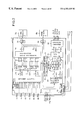
- FIG. 2 Shown in FIG. 2 is a schematic block diagram of the liquid crystal controller 3 in the first embodiment of the present invention.
- the STN liquid crystal controller 3 shown in FIG. 2 is designed for such a super twisted nematic (STN) liquid crystal display of a passive matrix display, dual scan type wherein a pixel is positioned at each of intersections between scan and data electrodes perpendicular to each other, the light transmission factor of the pixel varies with a mean square of differences between voltages applied to the scan and data electrodes, a display screen is divided into upper and lower screens to be driven at the same time. It is assumed that the display screen is of an extended graphics array (XGA) type having a resolution of 1024 ⁇ 768 dots.
- XGA extended graphics array
- reference numeral 21 denotes an FRC operator for performing intermediate gray-scale operation based on the FRC system
- 22 and 32 data width converters 23 and 30 groups of line memories, 24 and 29 data selector/data width converters, 25 and 26 frame memory read/write controllers, 8 a and 8 b frame memories for conversion of drive frame frequency, 31 a data selector, 33 and 34 line memory controllers, 35 a timing signal generator.
- reference symbols RA and RB denote red (R) gray-scale data of 6 bits per pixel
- GA and GB denote green (G) gray-scale data of 6 bits per pixel
- BA and BB denote blue (B) gray-scale data of 6 bits per pixel.
- R red
- GA and GB denote green
- BA and BB denote blue (B) gray-scale data of 6 bits per pixel.
- RA, GA and BA indicate gray-scale data of the respective colors with respect to the odd-numbered pixels
- RB, GB and GB indicate gray-scale data of the respective colors with respect to the even-numbered pixels.
- output signals of the respective circuits are illustrated to have 6, 16, 8 and 12 bits.
- DotCK denotes a synchronous signal synchronized with the gray-scale data
- Hsync denotes a horizontal synchronous signal indicative of a change-over of the horizontal period
- Vsync denotes a vertical synchronous signal (frame period signal) indicative of a change-over of the vertical (frame) period
- DispTMG denotes a signal DispTMG indicative of an effective indicate period.
- Reference symbol OA denotes liquid crystal display data of 12 bits in parallel associated with the upper display screen of the liquid crystal display 9
- symbol OB denotes liquid crystal display data of 12 bits in parallel associated with the lower display screen of the liquid crystal display 9 .
- Reference symbol CL 2 denotes a synchronous signal CL 2 synchronized with the liquid crystal display data
- CL 1 denotes a horizontal synchronous signal indicative of a change-over of the horizontal period
- FLM denotes a frame period signal (vertical synchronous signal) indicative of a change-over of the frame period (vertical period).
- the frequency of the frame period signal FLM to be output to the liquid crystal display 9 is set to be 2.5 times the frequency of the frame period signal Vsync of the input signals. Accordingly, 5 frame periods in the output signal are completed with 2 frame periods in the input signal.
- access control to the frame memories 8 a and 8 b is carried out with 2 frame periods of the input signal as a unit.
- timing signal generator 35 Explanation will first be made as to the timing signal generator 35 .
- the timing signal generator 35 on the basis of the synchronous signals DotCK, Hsync, Vsync and DispTMG applied to the liquid crystal controller 3 , generates the signals FLM, CL 1 , CL 2 and other control signals (such as read/write clocks).
- the signals DotCK, Hsync, Vsync and DispTMG as the input signals of the STN liquid crystal controller 3 may have timing as that of signals shown in Hitachi LCD controller/driver LSI data book, p. 1001, published by Hitachi Ltd. as shown in FIG. 27 .
- the signals CL 2 , CL 1 and FLM generated by the timing signal generator 35 may have timing as that of signals CL 2 , CL 1 and FLM shown in the same data book as the above, p. 1028.
- the timing signal generator 35 will be explained later in more detail.
- the FRC operator 21 generates 3 types of indicate on/off data per pixel for the gray-scale data RA, RB, GA, GB, BA and BB. This causes the indicate on/off data corresponding to 3 frames of the video output signal, i.e., 3 FRC patterns to be generated from the gray-scale data corresponding one frame of the video input signal.
- the FRC operator 21 has FRC processing circuits provided as associated with the respective gray-scale data RA, RB, GA, GB, BA and BB.
- Each of the FRC processing circuits generates 3 types of indicate on/off data per pixel for the associated gray-scale data.
- FIG. 3 is a schematic block diagram of FRC processing circuits or decoders 101 to 104 .
- Reference numeral 105 denotes a Vsync counter and numeral 106 denotes a write data selector.
- Vsync counter 105 counts the vertical synchronous signal Vsync and outputs a Vsync count value of 2 bits.
- Vsync count value can take a value of 0 to 3.
- the FRC decoders 101 to 104 with respect to the input gray-scale data of a pixel, generate indicate on/off data associated with the value of the gray-scale data.
- FIG. 4 Shown in FIG. 4 is a schematic block diagram of other FRC decoders 101 to 104 .
- the FRC decoders 101 to 104 include an FRC pattern generator 107 for generating indicate on/off data for generation of 64 types of FRC patterns associated with bits (6 bits) of the gray-scale data per pixel, and a selector 108 for selecting one of the 64 types of indicate on/off data generated by the FRC pattern generator 107 .
- FIG. 5 is a timing chart for explaining the output indicate on/off data of the FRC decoders 101 to 104 as well as read/write control of the frame memories 8 a and 8 b.
- FRC processing data A is illustrated therein as the indicate on/off data issued from the FRC decoder 101
- FRC processing data B is as the indicate on/off data issued from the FRC decoder 102
- FRC processing data C is as the indicate on/off data issued from the FRC decoder 103
- FRC processing data D is as the indicate on/off data issued from the FRC decoder 104 .
- a plurality of D-FNs (N being an integer) mean indicate on/off data of the FRC pattern to be output at the N-th frame.
- the FRC decoder 102 As shown in FIG. 5, assuming that the indicate on/off data generated by the FRC decoder 101 form an FRC pattern to be output at the N-th frame, then the FRC decoder 102 generates indicate on/off data for formation of an FRC pattern to be output at the (N+1)-th frame, the FRC decoder 103 generates indicate on/off data for formation of an FRC pattern to be output at the (N+2)-th frame, and the FRC decoder 104 generates indicate on/off data for formation of an FRC pattern to be output at the (N+3)-th frame.
- the FRC decoders 101 to 104 generates indicate on/off data for formation of an FRC pattern to be output at a frame previous by 2 frames each time the Vsync count value issued from the Vsync counter 105 is incremented by 1; and generates indicate on/off data for formation of an FRC pattern to be output at a frame previous by 4 frames each time the Vsync count value is reset, i.e., is switched from “3” to “0”.
- the present embodiment is designed to FRC patterns corresponding in number to the number of frames (Vsync) included in one period (sometimes referred to as the FRC period) of the FRC operation.
- a plurality of P-FNs denote the FRC patterns to be output at the N-th frame.
- the FRC patterns shown in FIG. 6 are arranged to be switched on a frame basis with use of 10 frames as one FRC period. Accordingly, the FRC patterns shown by P-F 11 to P-F 16 are the same as the FRC patterns shown by P-F 1 to P-F 6 .
- the FRC decoders 101 to 104 are set to generate indicate on/off data for formation of such FRC patterns as shown in FIG. 7, with respect to input pixels.
- the FRC pattern A is made up of indicate on/off data issued from the FRC decoder 101
- the FRC pattern B is made up of indicate on/off data issued from the FRC decoder 102
- the FRC pattern C is made up of indicate on/off data issued from the FRC decoder 103
- the FRC pattern D is made up of indicate on/off data issued from the FRC decoder 104 .
- the write data selector 106 selects indicate on/off data corresponding to 3 of 4 FRC patterns issued from the FRC decoders 101 to 104 .
- the write data selector 106 selects the indicate on/off data (which form the first FRC pattern denoted by D-F 1 (1st)) issued from the FRC decoder 101 , selects the indicate on/off data (which form the second FRC pattern denoted by D-F 2 (2nd)) issued from the FRC decoder 102 , and selects the indicate on/off data (which form the first FRC pattern denoted by D-F 3 (3rd)) issued from the FRC decoder 103 .
- the write data selector 106 selects the indicate on/off data (which form the fourth FRC pattern denoted by D-F 4 (4th)) issued from the FRC decoder 102 , selects the indicate on/off data (which form the fifth FRC pattern denoted by D-F 5 (5th)) issued from the FRC decoder 103 , and selects the indicate on/off data (which form the sixth FRC pattern denoted by D-F 6 (6th)) issued from the FRC decoder 104 .
- the respective indicate on/off data will be also denoted by 1st to 6th.
- FRC operator 21 in the present embodiment has such FRC processing circuits as shown in FIG. 3, with respect to the respective gray-scale data (RA, RB, GA, GB, BA, BB) applied to the liquid crystal controller 3 .
- the FRC operator 21 can generate indicate on/off data (1st, 2nd, 3rd or 4th, 5th, 6th) corresponding to 3 frames on the basis of gray-scale data corresponding to one frame.
- the indicate on/off data of 3 types of FRC patterns are output in 2-bit parallel, for each color R, G or B.
- the data width converter 22 converts 3 types of indicate on/off data (1st, 2nd, 3rd or 4th, 5th, 6th) of 2-bit parallel issued from the FRC operator 21 for each color R, G or B into indicate on/off data of 16-bit parallel.
- FIG. 8 shows a timing chart for explaining the operation of the data width converter 22 shown in FIG. 2 .
- Reference symbol PRA denotes indicate on/off data corresponding to the gray-scale data RA
- symbol PGA denotes indicate on/off data corresponding to the gray-scale data GA
- PGB denotes indicate on/off data corresponding to the gray-scale data GB
- PBA denotes indicate on/off data corresponding to the gray-scale data BA
- PBB denotes indicate on/off data corresponding to the gray-scale data BB.
- symbols RN, GN and BN denote indicate on/off data corresponding to the gray-scale data of the N-th pixel.
- the data width converter 22 rearranges the indicate on/off data of the respective colors issued from the FRC operator 21 in such a manner that the pixels are in order and the colors in the pixels are in the order of R, G and B, e.g., in such an order as R 0 , G 0 , B 0 , R 1 , G 1 , B 1 , R 2 , . . . , as shown in FIG. 8 .
- the data width converter 22 outputs a plurality of pieces of data (corresponding to 16 data in the illustrated example) on a parallel basis.
- Such operation as mentioned above can be realized, for example, by using a plurality of buffers or the like and controlling writing and reading operations of the indicate on/off data to and from the buffers.
- the line memory group 23 is arranged as shown in FIG. 2, so that a plurality of line memories having a 16-bit bus width are connected in parallel.
- the line memory controller 33 writes therein the 3 types of indicate on/off data (1st, 2nd, 3rd or 4th, 5th, 6th) of 16-bit parallel issued from the data width converter 22 sequentially by an amount corresponding to every 2 lines, and reads out it after a time corresponding to twice that of the write signal Hsync.
- a read clock from the line memory group 23 is controlled to be faster than a write clock to the line memories.
- FIG. 9 is a timing chart for explaining the indicate on/off data output bus width converting operation of the data selector/data width converter 24
- FIGS. 10 and 11 are timing charts for explaining the indicate on/off data order rearranging operation of the data selector/data width converter 24 .
- the data selector/data width converter 24 converts the indicate on/off data of 16-bit parallel read out from the line memory group 23 to indicate on/off data of 8-bit parallel.
- the line memory controller 33 controls the line memory group 23 in such a manner that the read clock of the indicate on/off data from the line memory group 23 is faster than the write clock into the line memory group 23 .
- the transmission rate of indicate on/off data subjected to the data width conversion by the data selector/data width converter 24 is set to be 4/3 times the transmission rate of the indicate on/off data applied to the line memory group 23 .
- the data selector/data width converter 24 read out the indicate on/off data from the line memory group 23 on every 2-line basis, rearranges the order of the 3 types of indicate on/off data (1st, 2nd, 3rd or 4th, 5th, 6th) having a data width converted to 8-bit parallel, and then convert them to indicate even-number-th lines of on/off data 1st-L and odd-number-th lines of indicate on-off data 2nd-L. And the data selector/data width converter 24 outputs the converted indicate on/off data during a period corresponding to twice that of the signal Hsync.
- FIG. 10 shows an example when 3 types of indicate on/off data read out from the line memory group 23 on every 2-line basis are 1st, 2nd and 3rd indicate on/off data, are converted to even-numbered lines of indicate on/off data 1st-L and odd-number-th lines of indicate on-off data 2nd-L, and then output during a next period corresponding to twice that of the horizontal synchronous signal Hsync.
- FIG. 11 shows an example when 3 types of indicate on/off data read out from the line memory group 23 on every 2-line basis are 4th, 5th and 6th indicate on/off data, are converted to even-numbered lines of indicate on/off data 1st-L and odd-number-th lines of indicate on-off data 2nd-L, and then output during a next period corresponding to twice that of the horizontal synchronous signal Hsync.
- the transmission rate of the indicate on/off data 1st-L and 2nd-L issued from the data selector/data width converter 24 are 3/2 times the transmission rate of the indicate on/off data applied to the line memory group 23 .
- the transmission rate of the indicate on/off data applied to the line memory group 23 shown in FIG. 9 is faster than 4/3 times of the transmission rate of the indicate on/off data subjected to the data width conversion.
- a horizontal retrace period corresponding to 64 or more signals DotCK is set to be provided in the input signals, while no horizontal retrace period is to be provided in write data to the frame memories 8 a and 8 b.
- 512 is obtained by dividing the number 1024 of clocks in the signal Dot during the signal sync by the number 2 of bits of the indicate on/off data.
- 4/3 indicates a ratio of the transmission rate of the indicate on/off data applied to the line memory group 23 with respect to the transmission rate of the indicate on/off data subjected to the data width conversion.
- the frame memory controllers 25 and 26 perform alternate switching between the read and write operations from and to the frame memories 8 a and 8 b on every unit time basis of twice the period of the signal Vsync.
- the frame memory 8 a is controlled to be put in its write state and the frame memory 8 b is to be put in its read state when the Vsync count value is “0” or “1”; whereas, the frame memory 8 a is controlled to be put in its read state and the frame memory 8 b is to be put in its write state when the Vsync count value is “2” or “3”.
- the data selector/data width converter 24 rearranges the order of 3 types of indicate on/off data (1st, 2nd, 3rd or 4th, 5th, 6th) of 8-bit parallel, converts them to even-number-th lines of indicate on/off data 1st-L and odd-number-th lines of indicate on/off data 2nd-L, and then output during a period corresponding to twice the period of the signal Hsync.
- even-number-th lines of indicate on/off data 1st-L of 8-bit parallel and odd-number-th lines of indicate on/off data 2nd-L of 8-bit parallel are written into the frame memories 8 a and 8 b, when the Vsync count value is “0” or “1” and “0” or “1”, respectively.
- FIGS. 12A and 12B Shown in FIGS. 12A and 12B is an example of storage locations of the indicate on/off data in the frame memories 8 a and 8 b.
- the liquid crystal controller 3 is supposed to be used for the STN liquid crystal display 9 of a so called dual scan type wherein upper and lower divisions of a display screen are driven at the same time.
- the indicate on/off data of pixels forming the display screen are stored in the frame memories 8 a and 8 b as divided into two pieces of data for the upper and lower display screens.
- the indicate on/off data are stored on a frame basis.
- ‘1st’ denotes a group of indicate on/off data forming the first display frame
- ‘2nd’ denotes a group of indicate on/off data forming the second display frame.
- Such allocation of storage locations to the frame memories 8 a and 8 b can be realized by referring to the signals Vsync and Hsync.
- HM5216165 manufactured by Hitachi Ltd. and explained in a book entitled “IC memory data book”, pp. 1023-1071.
- the data selector/data width converter 29 will next be explained.
- the data selector/data width converter 29 adjusts read timing of the indicate on/off data from the frame memories 8 a and 8 b so that the indicate on/off data can be transmitted at a transmission rate corresponding to 4/5 times the transmission rate when the indicate on/off data were written into the frame memories 8 a and 8 b.
- FIG. 13 is a timing chart showing the read timing of the indicate on/off data from the frame memories 8 a and 8 b, with write and read clocks to the frame memories 8 a and 8 b used as its time axis.
- the data selector/data width converter 29 reads the indicate on/off data of the upper display and the indicate on/off data of the lower display from the frame memories 8 a and 8 b.
- FIG. 14 is a timing chart showing read timing of the indicate on/off data from either one of the frame memories 8 a and 8 b, with the signals Hsync and CL 1 used as its time axis.
- N+384.LINE and subsequent data indicate the indicate on/off data of lines for the lower display.
- the transmission rate of indicate on/off data read out from the frame memories 8 a and 8 b is set to be 4/5 times the transmission rate (corresponding to twice the period of the signal Vsync and thus to 6 frames) when the indicate on/off data were written in the frame memories 8 a and 8 b.
- the drive frame frequency FLM of liquid crystal output data becomes;
- Vsync ⁇ 5/4 ⁇ 2 (for driving of two upper and lower displays) 2.5 Vsync
- the drive frame frequency to be output to the STN liquid crystal display is 2.5 times the drive frame frequency of the input signal.
- the data selector/data width converter 29 converts the data width of the respective indicate on/off data of the upper and lower displays read out alternately from the frame memories 8 a and 8 b on every 2-line basis, from 8-bit parallel to 16-bit parallel.
- reference symbol 1st-L′ denotes 16-bit parallel indicate on/off data associated with the indicate on/off data of the upper and lower displays read out from the frame memory 8 a
- reference symbol 2nd-L′ denotes 16-bit parallel indicate on/off data associated with the indicate on/off data of the upper and lower displays read out from the frame memory 8 b.
- the line memory group 30 is made up of line memories Ab to Db of a 16-bit bus width.
- the line memory controller 34 controls write and read operations of the 16-bit parallel indicate on/off data 1st-L′ and 2nd-L′ issued from the data selector/data width converter 29 .
- FIG. 15 is a timing chart showing write and read operations of indicate on/off data to and from the line memory group 30 as well as timing of indicate on/off data issued to the data selector 31 .
- the data selector/data width converter 29 alternately outputs 2 lines of 16-bit parallel indicate on/off data with respect to the upper and lower displays.
- the line memory controller 34 controls the write and read operations of 2 lines of 16-bit parallel indicate on/off data sequentially issued from the data selector/data width converter 29 with respect to the line memory group 30 , to thereby output the indicate on/off data of lines of the upper and lower displays from any two of output terminals a to e of the line memory group 30 simultaneously.
- the data 1-Line written in the Line memory Ab is read out therefrom and output from the output terminal a, in synchronism with the output of the data 385-Line from the output terminal e.
- the data 2-Line written in the Line memory Bb as well as the data 386-Line written in the line memory Cb are read out therefrom and output simultaneously from the respective output terminals b and c.
- the data selector 31 controls, as shown in FIG. 2, the indicate on/off data of lines of the upper and lower displays simultaneously issued from any two of the output terminals a to e of the line memory group 30 in such a manner that the indicate on/off data of lines of the upper display is output from the output terminal f and the indicate on/off data of lines of the lower display is output from the output terminal g.
- the data width converter 32 will then be explained.
- the data width converter 32 converts the data width of the indicate on/off data of lines of the upper and lower displays issued from the data selector 31 , to 12-bit parallel data for the liquid crystal 9 , respectively.
- the 12-bit parallel data (24 bits in total) of the upper and lower displays are output to the liquid crystal display 9 , together with the signals CL 1 , CL 2 and FLM generated in the timing signal generator 35 .
- indicate on/off data of 3 frames of the output signals are written in the frame memories 8 a and 8 b, and the 3 lines of indicate on/off data written therein are sequentially read out therefrom in synchronism with the frame period FLM of the output signal.
- the data written in the frame memories 8 a and 8 b are one bit of indicate on/off data subjected to the FRC operation, whereby the data bus width at the time of accessing the frame memories can be reduced to 16 lines per one frame memory.
- the FRC patterns can be switched for every frame period FLM of the output signal having a frame frequency corresponding to 2.5 times the input frame frequency.
- the object of the present invention that is, the reduction of flow of the intermediate gray-scale display portion and increase in the number of pins caused by formation of it in the form of an LSI can be suppressed.
- the total number of bits in the data written in the frame memories 8 a and 8 b becomes (number of pixels of one frame) ⁇ (3 frames) ⁇ (one bit).
- the total number of bits in the data written in the frame memories 8 a and 8 b during one frame period of the input signal becomes (the number of pixels in one frame) ⁇ (6 bits).
- the memory capacity can be saved.
- FIG. 16 there is shown a schematic block diagram of a liquid crystal controller in the second embodiment of the present invention.
- the liquid crystal controller 3 shown in FIG. 16 is intended for use with an STN liquid crystal display of a so-called dual scan type wherein upper and lower screens of a display are driven simultaneously.
- the display screen is of a so-called XGA type having a resolution of 1024 ⁇ 768 dots.
- reference symbol 21 a denotes an FRC operator for performing the intermediate gray-scale operation of an FRC system
- symbols 25 a and 26 a denote frame memory controllers
- symbol 29 a denotes a data selector/data width converter.
- the drive frame frequency FLM of liquid crystal output data is set to be 2.5 times the frame frequency Vsync of the input signal (gray-scale data); whereas, in the liquid crystal controller 3 of the present embodiment of FIG. 16, the drive frame frequency FLM of the liquid crystal output data is set to be 3 times the frame frequency Vsync of the input signal (liquid crystal data).
- one frame period of the input signal corresponds to 3-frame period of the output signal.
- access control to the frame memories 8 a and 8 b is carried out with use of one frame period of the input signal as a unit.
- the FRC operator 21 a will first be explained.
- the FRC operator 21 a With respect to gray-scale data RA, RB, GA, GB, BA and BB applied to the liquid crystal controller 3 ; the FRC operator 21 a generates 3 types of indicate on/off data per pixel. This causes 3 frames of indicate on/off data, i.e., 3 FRC patterns to be generated from one frame of gray-scale data.
- the FRC operator 21 a has FRC processing circuits provided for the respective gray-scale data RA, RB, GA, GB, BA and BB.
- the FRC processing circuits generate 3 types of indicate on/off data per pixel, with respect to the corresponding gray-scale data.
- FIG. 17 Shown in FIG. 17 is a schematic block diagram of the FRC processing circuits.
- reference symbols 101 a to 103 a denote FRC decoders
- symbol 105 a denotes a Vsync counter
- the Vsync counter 105 a counts the signal Vsync and outputs one bit of Vsync count value. Accordingly, the Vsync count value can take “0” or “1”.
- the FRC decoders 101 a to 103 a With respect to the input gray-scale data of a pixel, the FRC decoders 101 a to 103 a generate indicate on/off data corresponding to the value of the gray-scale data.
- FIG. 18 is another schematic block diagram of the FRC decoders 101 a to 103 a.
- the FRC decoders 101 a to 103 a include an FRC pattern generator 107 a for generating indicate on/off data for formation of 64 types of FRC patterns associated with bits (6 bits) of gray-scale data per pixel and also include a selector 108 a for selecting indicate on/off data of one of the 64 types of indicate on/off data generated by the FRC pattern generator 107 a according to the value of the input gray-scale data of a pixel.
- FIG. 19 is a timing chart for explaining indicate on/off data issued from the FRC decoders 101 a to 103 a as well as read/write control of the frame memories 8 a and 8 b.
- FRC processing data A is indicate on/off data issued from the FRC decoder 101 a
- FRC processing data B is indicate on/off data issued from the FRC decoder 102 a
- FRC processing data C is indicate on/off data issued from the FRC decoder 103 a.
- Reference symbol D-FN (N being an integer) denotes indicate on/off data forming FRC patterns to be issued at the N-th frame.
- the FRC decoder 102 a As shown in FIG. 19, assuming that indicate on/off data generated by the FRC decoder 101 a form FRC patterns to be output at the N-th frame, then the FRC decoder 102 a generates indicate on/off data for formation of FRC patterns to be output at (N+1)-th frame, and the FRC decoder 103 a generates indicate on/off data for formation of FRC patterns to be output at the (N+2)-th frame.
- Each of the FRC decoders 101 a to 103 a generates indicate on/off data to be output at a frame previous by 3 frames each time the Vsync count value issued from the Vsync counter 105 a varies.
- the FRC operator 21 a of the present embodiment has such FRC processing circuits as shown in FIG. 17 provided for the respective gray-scale data RA, RB, GA, GB, BA and BB applied to the liquid crystal controller 3 .
- the FRC operator 21 a generates indicate on/off data of 3 frame, that is, 3 FRC patterns, from the gray-scale data of one frame for each of the gray-scale data RA, RB, GA, GB, BA and BB.
- the indicate on/off data of the 3 types of FRC patterns are respectively output in a 2-bit parallel manner for each color of R, G or B.
- the frame memory controllers 25 a and 26 a alternately switch the read/write operations from and to the frame memories 8 a and 8 b for every signal Vsync.
- the frame memory controllers 25 a and 26 a control the frame memories 8 a and 8 b in such a manner that the frame memory 8 a is put in its write state and the frame memory 8 b is put in its read state when the Vsync count value is “0”, and that the frame memory 8 a is put in its read state and the frame memory 8 b is put in its write state when the vsync count value is “1”.
- the data selector/data width converter 29 a controls read timing of the indicate on/off data from the frame memories 8 a and 8 b in such a manner that the indicate on/off data can be transmitted at the same transmission rate as that at the time of writing the indicate on/off data in the frame memories 8 a and 8 b.
- FIG. 20 is a timing chart showing the read timing of the indicate on/off data from the frame memories 8 a and 8 b, with use of write and read clocks to the frame memories 8 a and 8 b as its time axis.
- the data selector/data width converter 29 a alternately reads out 2 lines of indicate on/off data of the upper and lower displays from the frame memories 8 a and 8 b.
- FIG. 21 is a timing chart showing read timing of the indicate on/off data from either one of the frame memories 8 a and 8 b, with use of the signals Hsync and CL 1 as its time axis.
- data (N+384.LINE) and subsequent data correspond to the indicate on/off data of lines of the lower display.
- a ratio between the horizontal period of the horizontal synchronous signal Hsync and the horizontal period of the horizontal synchronous signal CL 1 of liquid crystal output data in the input signal is 4 times the period of the signal Hsync and 6 times the period of the signal CL 1 .
- the drive frame frequency to be output to the liquid crystal display 9 becomes 3 times the drive frame frequency of the input signal.
- the data selector/data width converter 29 a converts the data width of the respective indicate on/off data of the upper and lower displays from 8-bit parallel to 16-bit parallel.
- symbol “1st-L′” denotes 16-bit parallel indicate on/off data corresponding to the indicate on/off data of the upper and lower displays read out from the frame memory 8 a
- symbol “2nd-L′” denotes 16-bit parallel indicate on/off data corresponding to the indicate on/off data of the upper and lower displays read out from the frame memory 8 b.
- data to be written in the frame memories 8 a and 8 b is subjected to the FRC processing to form one bit of indicate on/off data, whereby the data bus width at the time of accessing the frame memories can be reduced to 16 per frame memory.
- the FRC pattern can be switched for every frame period FLM of the output signal having a frequency corresponding to 3 times the frequency of the input frame frequency.
- data stored in the frame memories 8 a and 8 b has 3 bits per pixel.
- the flow of the intermediate gray-scale display part can be lightened and an increase in pins caused by the formation of an LSI can be suppressed.
- the memory capacity can be made smaller.
- the foregoing explanation has been made in connection with the case where the frame frequency of the liquid crystal output data is 2.5 times and 3 times the frame frequency of the input signal.
- the present invention is not limited to the specific example, but the same concept as in the above first and second embodiments may be realized, for example, even when the frame frequency of the liquid crystal output data is set to be twice the frame frequency of the input signal.
- liquid crystal controller for the STN liquid crystal display of a so-called dual scan type has been explained, the present invention may be widely applied as the liquid crystal controller for a liquid crystal display of a passive matrix type.
- the liquid crystal controller 3 in the first and second embodiments may be made in the form of an LSI.
- the liquid crystal controller 3 in the form of an LSI is disposed, together with the frame memories 8 a and 8 b, within a liquid crystal module, e.g., on a printed circuit board having a liquid crystal driver mounted thereon or on a rear side thereof.
- the interface of the liquid crystal module can be made to be the same as the interface of a digital RGB or TFT liquid crystal having a plurality of bits of gray-scale information.
- the liquid crystal controller 3 in the first and second embodiments of the present invention may be arranged to incorporate the frame memories 8 a and 8 b, in which case additional space saving can be realized.
- the single liquid crystal controller 3 can be commonly used to the first and second embodiments.
- mode change-over between the first and second embodiments can be implemented, e.g., with use of signal input terminals or the like.
- the liquid crystal controller 3 when used for the so-called dual scan type of STN liquid crystal display to provide intermediate gray-scale display over the upper and lower displays, it sometimes appears that the interference fringes of the FRC display look like moving at a boundary between the upper and lower displays.
- FIG. 22 is a diagram for explaining interference fringes generated when the liquid crystal controller 3 is used to display FRC patterns over the upper and lower display screens of a dual scan type of STN liquid crystal display 9 .
- the illustrated example shows a manner vertical FRC patterns move for each frame.
- scanning is carried out on line-after-line basis on the STN liquid crystal display 9 , so that, even the leading line of the lower display is already scanned, the last line of the upper display is not scanned yet, still leaving the pattern of the previous line.
- the vertical line of the lower display looks like moving somewhat forwardly and thus the upper and lower displays lose the continuity in its looking manner of the display data.
- the liquid crystal controller 3 of the present embodiment is arranged, as shown in FIG. 23, to output the FRC patterns of the lower display as delayed by one frame when compared with those of the upper display.
- FIG. 24 Shown in FIG. 24 is a block diagram of a major arrangement of the liquid crystal controller 3 in the third embodiment of the present invention.
- reference numeral 241 denotes an FRC operator for the upper display
- numeral 242 denotes an FRC operator for the lower display
- 243 denotes a pattern selector
- 244 denotes a pattern selector controller.
- the liquid crystal controller 3 of the present embodiment corresponds to the liquid crystal controller 3 of the first embodiment of the present invention but the FRC operator 21 is replaced by such an arrangement as shown in FIG. 24 .
- the FRC operator 241 for the upper display and the FRC operator 242 for the lower display are basically the same as those in the first embodiment of FIG. 2, except that the FRC operator 242 for the lower display is set to generate indicate on/off data delayed by one frame with respect to the FRC operator 21 for the upper display.
- the pattern selector controller 244 counts the number of clocks in the input signal Hsync immediately after the input signal DispTMG becomes active. And the pattern selector controller 244 controls the pattern selector 243 to cause the pattern selector 243 to select outputs of the FRC operator 241 for the upper display until the count value becomes half of the resolution of the gray-scale data (e.g., 0-384 counts for an XGA type having a resolution of 1024 ⁇ 768 dots).
- the pattern selector 243 selects the output of the FRC operator 242 for the lower display.
- the count value of the signal Hsync is reset by the signal Vsync.
- the FRC patterns of the lower display can be output ag delayed by one frame with respect to those of the upper display with the aforementioned arrangement. This enables prevention of such a phenomenon that interference fringes look like moving at the boundary between the upper and lower displays.
- FIG. 24 Although the arrangement shown in FIG. 24 has been explained in the present embodiment in connection with the case of applied to the first embodiment of the present invention, this arrangement can be applied to a liquid crystal controller for the ordinary dual type of STN display.
- FIG. 25 schematically shows an arrangement of the liquid crystal display apparatus in accordance with the fourth embodiment of the present invention.
- reference numeral 251 denotes an A/D converter
- numeral 3 denotes the liquid crystal controller already used in the first to third embodiments
- reference symbols 8 a and 8 b denote the frame memories already explained in the foregoing explanation
- numeral 9 denotes the liquid crystal display of the dual scan type already explained above.
- the A/D converter 251 on the basis of analog display data of red (R), green (G) and blue (B) for use in a CRT monitor, generates gray-scale data RA, RB, GA, GB, BA and BB of 6 bits per pixel.
- the A/D converter extracts the analog display data of R, G and B in units of pixel and converts it to gray-scale data of 6 bits. And the converter outputs the data RA, GA and BA when the order of the pixel specified by the gray-scale data is even; while it outputs the data RB, GB and BB when the order of the pixel specified by the gray-scale data is odd.
- the pixel order can be found by providing such a counter that increments the pixel order according to the signal DotCK and resets it according to the signal Vsync.
- FRC patterns generated by the liquid crystal controller 3 are set as follows.
- FIG. 26 is a diagram for explaining FRC patterns generated in the fourth embodiment of the present invention.
- the number of ON indicates is added while keeping the positions of ON and OFF indicates in the FRC pattern of the current gray scale ratio at their initial positions. Even when the frame is changed to another frame, the FRC pattern is set so that this relationship is always kept.
- the sixth embodiment is directed to the timing signal generator 35 in the liquid crystal controller 3 shown in FIGS. 2 and 16. That is, the present embodiment generates a video signal corresponding to an input video signal but its retrace periods removed therefrom, and subsequent circuit configurations are all included in the timing signal generator 35 .
- Explanation of the sixth embodiment will start with how a video signal is displayed on the liquid crystal display 9 , by referring to FIG. 48 corresponding to FIG. 1 .
- an upper display 500 of the liquid crystal display 9 is driven by a scan driver 502 and a data driver 504 .
- a lower display 501 is driven by a scan driver 503 and a data driver 505 .
- the data drivers receive supply of a plurality of levels of gray-scale voltages and apply to data lines the gray-scale voltages of levels corresponding to the received display data.
- the scan drivers apply select pulses to scan lines to be displayed.
- the liquid crystal controller 3 includes, as its major functional blocks, a mode establish circuit 506 for mode setting, a vertical synchronous control circuit 507 , a horizontal synchronous control circuit 508 for generating a horizontal synchronous signal, an indicate access control circuit 509 for accessing of the frame memories, an FRC access control circuit 510 for accessing of an FRC setting memory, an FRC access circuit 511 for gray-scale display control of display data, and an indicate period control circuit 512 for coping with change in the number of lines in the display data.
- a mode establish circuit 506 for mode setting
- a vertical synchronous control circuit 507 for generating a horizontal synchronous signal
- an indicate access control circuit 509 for accessing of the frame memories
- an FRC access control circuit 510 for accessing of an FRC setting memory
- an FRC access circuit 511 for gray-scale display control of display data
- an indicate period control circuit 512 for coping with change in the number of lines in the display data.
- the vertical synchronous control circuit 507 on the basis of an input synchronous signals received from the system reality 1 , generates and outputs a vertical synchronous signal faster than the received vertical synchronous signal.
- An the vertical synchronous signal is commonly supplied from the vertical synchronous control circuit 507 to the respective drivers of the liquid crystal display 9 .
- mode setting data taken in by the mode establish circuit 506 cause the speed of the generated vertical synchronous signal to becomes either one of 2, 2.5 and 3 times the speed of the received vertical synchronous signal. Accordingly, even on the screen of the liquid crystal display 9 , its frame rate becomes either one of 2, 2.5 and 3 times, thus providing a high quality of image display.
- the horizontal synchronous control circuit 508 on the basis of the input synchronous signals received from the system reality 1 , generates and outputs a horizontal synchronous signal equal to or faster than the received horizontal synchronous signal. And the horizontal synchronous signal is also supplied commonly to the respective drivers of the liquid crystal display 9 .
- the mode setting data taken in by the mode establish circuit 506 cause the speed of the generated horizontal synchronous signal to become equal to or faster than the speed of the received horizontal synchronous signal.
- the frame rate is twice, the speed of the horizontal synchronous signal becomes unity.
- the speed of the horizontal synchronous signal becomes higher than unity.
- the speed up of the horizontal synchronous signal is realized by shortening the retrace period (in which valid display data is not output).
- the data synchronous signal received from the system reality 1 is used as a reference clock for driving of circuits in the liquid crystal controller 3 .
- the data synchronous signal of the same speed as the reference clock is also supplied to the data drivers of the liquid crystal display 9 . Even when the speed of the horizontal synchronous signal is made faster, all valid display data can be displayed during one frame period without any need for making fast the speed of the data synchronous signal, because the retrace period is made short.
- the FRC access circuit 511 holds in its internal register the gray-scale pattern data read out from the FRC establish memory 6 by the FRC access control circuit 510 , changes the values of the display data received from the system reality 1 according to a pattern specified by the held gray-scale pattern data to thereby provide intermediate gray-scale display. More specifically, display of a single piece of the input display data is carried out with use of a plurality of frames, and at least two pieces of display data corresponding to the display data are selectively output. This results in that, even when the number of gray-scale levels in the input display data is larger than the number of gray-scales (the number of gray-scale voltage levels) displayable by usual driving of the liquid crystal display 9 for example, the display of the intermediate gray scale corresponding to the input display data can be realized. In this connection, this function may be used also as a function of correcting display characteristics of the liquid crystal display 9 .
- the indicate access control circuit 509 sequentially writes the display data subjected to the gray scale control by the FRC access circuit 511 into the frame memory 8 by an amount corresponding to one frame on every scan line basis. Concurrently with the above operation, the indicate access control circuit 509 individually reads out display data of the upper display and display data of the lower display from the frame memory 8 according to the above output synchronous signals, and outputs it to the associated data drivers 504 and 505 . In this case, reading of the respective display data of the upper and lower displays starts with respective predetermined head addresses of the upper and lower displays. The head address of the lower display corresponds to an addition of the capacity of all display data of the upper display to the head address of the upper display.
- the indicate period control circuit 512 detects the number of valid display lines in the TFT digital video signal 2 (see FIG. 1) from the input synchronous signals, and when the number of valid display lines is changed, the circuit 512 finds respective display periods of the upper and lower displays in one frame through calculation. And the circuit 512 outputs an indicate period signal to the respective data driver of the upper and lower displays to specify the respective indicate periods.
- the mode establish circuit 506 which is connected to a terminal of the liquid crystal controller 3 to provide an address signal to an address terminal of the frame memory 8 , takes in various sorts of setting data from the terminal and holds it in its internal register at the time of starting the system. And thereafter, the mode establish circuit 506 opens the terminal for output of the address signal.
- the mode setting data held in the register are supplied to the associated constituent elements.
- the mode setting data include display mode (XGA, SVGA) and double-speed mode for specification of how many times higher than the frame rate.
- the mode establish circuit 506 takes in mode setting data.
- the FRC access control circuit 510 causes gray-scale pattern data to be read out from the FRC establish memory 6 and to be written in a table within the FRC access circuit 511 .
- the vertical synchronous control circuit 507 and horizontal synchronous control circuit 508 on the basis of the input synchronous signals of the TFT digital video signal 2 , generate vertical and horizontal synchronous signals to form output synchronous signals and to output them to the drivers of the liquid crystal display 9 .
- the speed of the vertical synchronous signal is doubled while the speed of the horizontal synchronous signal remains as it is.
- the scan drivers 502 and 503 of the upper and lower displays sequentially scan lines respectively at the same timing from top to bottom according to the supplied output synchronous signals, and this is repeated.
- display data included in the TFT digital video signal 2 are subjected to gray-scale display control by the FRC access circuit 511 , and then sequentially written into the frame memory 8 by the indicate access control circuit 509 .
- the indicate access control circuit 509 according to the output synchronous signals, individually reads out the upper display data and lower display data of the liquid crystal display 9 from the frame memory 8 .
- the display data are output to the associated display data drivers 504 and 505 .
- the data drivers 504 and 505 takes in the above display data and holds therein on a line basis according to the supplied output synchronous signals. And gray-scale voltages associated with the display data of scan lines selected by the scan drivers are, all together, applied to the data lines. This enables simultaneous display of the first scan lines of the upper and lower displays 500 and 501 of the liquid crystal display 9 . And sequential shift of lines to be displayed enables the entire display 9 to be fully displayed as shown in FIG. 40A during one period of the output vertical synchronous signal.
- the indicate period control circuit 512 detects a change (from 768 to 600 lines) in the number of valid display lines and sets a subtraction of the number of all display lines in the upper display from the number of valid display lines as the display line number of the lower display. And the indicate period signal causes indicate periods of the respective display lines to be specified in the data driver.
- the liquid crystal display control apparatus of the present embodiment can display a good quality of image with use of the reference clock and without involving any modification of the speed of the data synchronous signal. Since the need for speeding up the data synchronous signal can be eliminated, it becomes unnecessary to operate the internal circuits and various drivers at high speed, thus eliminating the need for a complicated delay design. As a result, there can be inexpensively implemented a liquid crystal display control apparatus.
- the respective indicate periods of the upper and lower displays can be found through calculation and individual display control can be realized for the respective displays, which results in that normal display can be attained in response to a change in the number of lines in the input video signal.
- liquid crystal controller 3 further, output of the address signal and input of the mode setting data can be carried out through the common terminal, the total number of necessary terminals can be reduced, enabling miniaturization of the liquid crystal controller 3 .
- liquid crystal controller 3 realizes all the functions mentioned above in the form of the operation of a pure hardware circuit.
- processing delay can be made smaller than the delay when the above functions are realized through program control, thus easy and inexpensive realization of the apparatus.
- a video signal for a liquid crystal display apparatus has XGA and SVGA modes as its main modes.
- the period of the input synchronous signal is a product of the total number of horizontal clocks (the total number of clocks in the data synchronous signal per one period of the horizontal synchronous signal) and the total number of vertical lines (the total number of clocks in the horizontal synchronous signal per one period of the vertical synchronous signal).
- the period of the input synchronous signal has 1328 ⁇ 806 dots for the XGA mode and has 1040 ⁇ 666 dots for the SVGA mode.
- the number of valid display data is 1024 ⁇ 768 dots for the XGA mode and 800 ⁇ 600 dots for the SVGA mode.
- the residual durations in the respective periods are retrace periods.
- numbers placed in parentheses denote clock numbers when a pair of display data are transmitted in a parallel manner.
- a 2-dot duration (clock) is reduced in one period of the horizontal synchronous signal, for example, (vertical one-line duration+about-300-clock duration) can be used as an idle duration for each of the XGA and SVGA modes, as given by the following expressions (1) and (2).
- such an idle duration is used to beforehand display the next frame.
- the output horizontal duration (the period of the horizontal synchronous signal of the output synchronous signals) is found in accordance with an equivalent expression to generate the output synchronous signals on the basis of the found output horizontal duration.
- Output horizontal duration [(input horizontal total clock number ⁇ )+(input total line number ⁇ input display line number ⁇ )] ⁇ multiple-speed mode ⁇ (3)
- the output horizontal duration found according to the above expression is recalculated only when the number of lines in one input frame is changed, in order to always be stabilized even when the input horizontal duration varies. This is for the purpose of preventing uneven display caused by fluctuations of the liquid crystal driver select/non-select durations based on fluctuations of the output horizontal duration.
- ⁇ and ⁇ are fixed values determined based on the secure reservation of the retrace period and circuit operational restrictions, are 10 and 4 respectively in the present embodiment.
- the subtraction of (input total line number ⁇ input display line number) in the above expression means to convert the input retrace period to an output horizontal clock number, whereby the retrace period of the output synchronous signals is compressed.
- the multiple-speed mode ⁇ in the above expression takes a value of 1, 1.25 or 1.5 for the double-speed, 2.5-time-speed mode or triple-speed mode specified by the mode setting, respectively.
- Half of each mode multiple-speed is set as each mode value. This is because the liquid crystal controller 3 scan the 2 upper and lower displays at the same time, which means the already doubling operation.
- FIG. 34 Schematically shown in FIG. 34 is an arrangement of the horizontal synchronous control circuit 508 .
- reference numeral 341 denotes a line number unagreement detector for each one input frame period
- numeral 342 denotes a clock number detector during one input horizontal period
- 343 denotes a vertical retrace period detector during one input frame period
- 344 denotes a clock generator for calculation of output horizontal period
- 345 denotes an output horizontal period calculation circuit 1
- 346 denotes a calculation circuit 2
- 347 denotes an output horizontal synchronous signal generator for generating a horizontal synchronous signal on the basis of calculation results of the output horizontal period calculation circuits 345 and 346 .
- the line number unagreement detector 341 compares the number (IVTIME) of lines in each one input frame with the number (A) of lines in the one-previous frame.
- the line number unagreement detector 341 latches the current frame line number and at the same time, outputs a line number unagreement signal by one frame period to the clock number detector 342 .
- the clock number detector 342 latches (D) hand holds the input horizontal clock number received from the input horizontal counter during one frame duration of the valid unagreement signal.
- calculation is carried out in accordance with the above expression (3) in a hardware manner.
- the clock number detector 342 subtracts the clock number ⁇ (10 in the illustrated example) from the input horizontal clock number (D) to obtain a subtraction and outputs the subtraction to the vertical retrace period detector 343 .
- the vertical retrace period detector 343 subtracts the fixed value ⁇ (4 in the illustrated example) based on the circuit operational restrictions, from a subtraction (i.e., vertical retrace period) of an input display line number (LIVDSPCNT) from an input one-frame line number (IVTIME), adds to its subtracted result the subtraction result received from the clock number detector 342 , and outputs a result of twice or 4 times the addition to the output horizontal period calculation circuit 345 .
- the calculation employs a pull-back method based on subtraction.
- the calculation circuit 346 latches the doubled or quadrupled input data at the same timing as the horizontal period, and shifts the data at the timing of a horizontal calculation clock (J) issued from the clock generator 344 for calculation of the output horizontal period.
- the calculation circuit 346 for calculation of the output horizontal period subtracts “5” or “3” from upper 4-bit data (K) received from the output horizontal period calculation circuit 345 .
- the subtraction uses an addition circuit of 2's complement.
- the subtraction result is positive when a carrier output (L) of the addition circuit is “1”, while the subtraction result is negative when the carrier output is “0”.
- Selection of “5” or “3” in the subtraction is determined by the multiple-speed mode setting at the time of starting the system. That is, “5” is selected in the subtraction for the 2.5-time-speed mode, and “3” is selected for the triple-speed mode.
- the carrier output (L) of the addition circuit is “1”
- remainder data after the subtraction is returned to the shift circuit of the output horizontal period calculation circuit 345 for its reflection in the subsequent calculation.
- Latch data (M) of the calculation circuit 346 for calculation of the output horizontal period at the time point of the shift completion becomes a final output horizontal period set value, which is output to the output horizontal synchronous signal generator 347 .
- the output horizontal synchronous signal generator 347 compares the latch data (M) with an output (N) of the output horizontal counter, and generates an output horizontal synchronous signal (OUTHSYNCP) by clearing the output horizontal counter with the coincided timing signal (O).
- an input horizontal counter clear signal (INHCNTCLRP) is used for clear control of the output horizontal counter of the output horizontal synchronous signal generator 347 .
- FIG. 35 only waveforms marked by * are explained and the other waveforms are illustrated only for the sake of reference.
- the vertical synchronous control circuit 507 will then be explained in connection with FIG. 36 .
- Table 1 shows a relationship between the number of lines in one output frame and how to process residual lines with respect to the respective multiple-speed modes in the present embodiment.
- the number of lines in one output frame is set to be a division of the number of input lines in one input frame by 2, remaining lines are assigned to the second output frame, and input and output are completed for each frame. Accordingly, when the number of lines in one input frame is odd, the number of lines in the second output frame is larger by one line than the number of lines in the first output line.
- FIG. 36 is a schematic arrangement of the vertical synchronous control circuit 507 .
- reference numeral 341 denotes the same line number unagreement detector as in FIG. 34
- numeral 362 denotes a line number detector for detecting the number of output horizontal period lines in one input frame
- 363 denotes a clock generator for calculation of output vertical period
- 364 denotes an output vertical period calculation circuit
- 365 denotes an output vertical period calculation circuit
- 366 denotes a remaining line distribution circuit functioning at the time of setting the 2.5-time-speed mode
- 367 denotes an output vertical synchronous signal generator.
- the vertical synchronous control circuit 507 similarly to the output horizontal synchronous signal generator 347 , outputs a line number take signal (C) to the line number detector 362 .
- the line number detector 362 triggers this signal to newly take in an output line number count value (E) in one input frame from an output line number counter as a new output line number count value (G).
- the output line number count value (G) taken in is selected at the time of setting 2.5-time-speed and triple-speed modes; while an input line number count value (IVTIME) in one input frame is selected at the time of setting the double-speed mode.
- the line number count value selected according to the multiple-speed mode setting is added by +1, the line number count value is output as it is to the output vertical period calculation circuit 364 at the time of setting the double-speed and triple-speed modes of every frame completion type, and the line number count value is doubled at the time of setting the 2.5-time-speed mode of 2-frame completion type and then output to the output vertical period calculation circuit 364 , respectively calculation data (H).
- the subsequent calculation is carried out with use of the pull-back method similar to the output horizontal synchronous signal generator 347 and at the timing of an operational clock (O) issued from the clock generator 363 for calculation of output vertical period.
- division control of remaining lines is carried out by outputting latch data (P) of the output vertical period calculation circuit 364 indicative of remaining lines at the end of the operation to the remaining line distribution circuit 366 .
- the remaining line distribution circuit 366 performs distribution control of remaining lines over the second output frame at the time of setting the 2.5-time-speed mode. Accordingly, the distribution of remaining lines over the final frame in all multiple-speed modes given in Table 1 is realized by outputting (synchronizing the input and output) a next input vertical synchronous signal (W) as an output vertical synchronous signal (OUTVSYNCP) according to an output synchronous signal select/change-over signal (Y) issued from the clock generator 363 for calculation of output vertical period.
- W next input vertical synchronous signal
- OUTVSYNCP output vertical synchronous signal
- Y output synchronous signal select/change-over signal
- the latch data (P) is compared with “2”, “3” and “4”. Since the coincided value becomes the total number of remaining lines, when the latch data coincides with “2” or “3”, the output vertical synchronous signal generator 367 adds “1” to an output vertical period calculation value (S) issued from the output vertical period calculation circuit 365 at the timing of the second output frame, compares the value added by “1” with a count value (T) of the output vertical counter, and outputs an output vertical synchronous signal (OUTVSYNCP) at the matched timing.
- S output vertical period calculation value issued from the output vertical period calculation circuit 365 at the timing of the second output frame
- the output vertical synchronous signal generator 367 adds “2” to the output vertical period calculation value (S) at the timing of the second output frame.
- the output vertical synchronous signal (OUTVSYNCP) generated based on the output vertical period set value which corresponds to an addition of the output vertical period (S) found by the output vertical period calculation circuits 364 and 365 to the remaining line distribution value for each set multiple-speed mode; the output frame frequency higher than the input frame frequency can be generated, whereby the liquid panel of the passive matrix type can provide a high quality of image display.
- FIGS. 37, 38 and 39 show waveforms of signals for explaining the operations of 2-, 2.5- and 3-time-speed modes as examples of high output frame frequency, respectively.
- the operational waveforms are the operations when the vertical synchronization control circuit shown by a schematic arrangement circuit in FIG. 36 is set at the operational modes at the time of starting the system.
- the doubled speed is realized by converting a one-period duration of the input vertical synchronous signal INVSYNCP to a 2-period duration of the output vertical synchronous signal OUTVSYNCP.
- the 2.5-time speed is realized by converting a 2-period duration of the input vertical synchronous signal INVSYNCP to a 5-period duration of the output vertical synchronous signal OUTVSYNCP.
- the triple speed is realized by converting a one-period duration of the input vertical synchronous signal INVSYNCP to a 3-period duration of the output vertical synchronous signal OUTVSYNCP.
- reference numeral 410 denotes an input valid display line number counter for counting the number of valid display lines of video data in one input frame
- numeral 411 denotes a comparator for comparing a count value (LIVDSPCNT) OF THE input valid display line number counter 410 with the number of prescribed lines (768 for the XGA mode and 600 for the SVGA mode) for each display mode
- 412 denotes an enable signal for enabling a circuit for prevention of display screen separation caused by lacked lines
- 413 denotes an output vertical counter for counting with the output horizontal period
- 414 denotes an upper display indicate pulse width generator in a lacked line mode
- 415 denotes a lower display indicate pulse width generator in the lacked line mode
- 416 denotes a selector circuit for selecting the lower display indicate pulse width generation signal
- 417 and 418 denote upper and lower display indicate pulse
- Assertions of the upper and lower display indicate pulses (OUTVDSPP and OUTLVDSPP) are equal to each other at the timing of clearing the output vertical counter 413 .
- the clear timing of the upper display indicate pulse is controlled by the upper display indicate pulse width generator 414 at the timing when the count value of the output vertical counter 413 becomes 384 ; whereas the clear timing of the lower display indicate pulse is controlled by the upper display indicate pulse width generator 414 selected by the selector circuit 416 at the timing when the count value of the output vertical counter 413 becomes a value (corresponding to a subtraction of the upper display indicate line number from the total input indicate line number) obtained by subtracting 384 from the count value (LIVDSPCNT) of the input valid display line number counter 410 .
- the upper and lower display indicate pulses are both cleared at the timing when the value (LSIVDSPCNT) corresponding to the division of the total input indicate line number (LIVDSPCNT) of the input valid display line number counter 410 by 2 coincides with the count value of the input valid display line number counter 410 .
- the number of indicate lines of input video data is a prescribed value (of 768)
- pulses of 384 lines corresponding to half of the prescribed 768 lines are generated as the upper and lower display indicate pulses, thus providing such a normal display as shown in FIG. 40 A.
- half of the prescribed value is also smaller than 384.
- the upper and lower display indicate pulse widths become both smaller than 384 lines and thus such a separated display of the upper and lower display screens as shown in FIG. 40 B.
- Waveforms given by marks * are already explained above and the other waveforms correspond to the counterpart signals of FIG. 41 .
- the present embodiment also has a function of forcibly increasing the number of output lines when the number of input lines is lacking.
- 116 registers of an 8 bit type are provided as the FRC control data setting registers and a serial memory of a type of 64 words ⁇ 16 bits is provided as a memory for storing data set in all the registers.
- Use of the serial memory enables reduction of the number of terminals necessary when the apparatus is made in the form of an LSI, contributing to a high density of mounting.
- FIG. 43 shows a schematic arrangement of the FRC access control circuit 510 .
- reference numeral 430 denotes a mode setting function part for controlling whether or not to set in the FRC access circuit 511 data from an external serial memory at the time of starting the system
- numeral 431 denotes a read enable signal/chip select signal generating function part to the external serial memory when the external serial memory is set to be valid
- 432 denotes a status signal/address generating function part to the serial memory
- 433 denotes a parallel/serial conversion & register write pulse generation part including a data converting function of converting serial data read out from the serial memory into parallel data and also including a register write pulse generating function of taking it into the FRC control register at the timing of completion of the conversion.
- an 8-bit counter 1 is initiated in the read enable signal/chip select signal generating function part 431 .
- the counter 1 is cleared whenever the count value (A) of the counter 1 counted by the input horizontal synchronous signal (IHSYNCP) also used as an external serial memory control clock (ROMCKP) counts 30 (1 Dh).
- a counter mask signal (D) for stopping counting of the 8-bit counter 2 becomes valid. By making the mask signal (D) valid, the operation of the present control circuit is thereafter stopped, thus preventing erroneous operation of the system.
- the read enable signal (ROMRDENP) indicates that control over the external serial memory is being carried out during the valid duration.
- the status signal/address generating function part 432 next triggers the serial memory chip select signal (ROMCSP) and outputs a status signal ( 110 ) indicative of read operation, followed by a serial memory address (ROMDI). At the same time, the status signal/address generating function part 432 also generates a register address (ILA[ 5 : 0 ]) for the FRC controller.
- ROMCSP serial memory chip select signal
- ROMDI serial memory address
- the parallel/serial conversion & register write pulse generation part 433 takes in its parallel/serial conversion circuit a count value (F) of an 8-bit counter 3 counted up by a clock (E) of the chip select signal (ROMCSP), and thereafter serially outputs (ROMDI) the status signal ( 110 ) and serial memory address in this order at the timing of the serial memory control clock (ROMCKP).
- the parallel/serial conversion & register write pulse generation part 433 outputs a signal corresponding to a subtraction of 1 from the count value (F) of the 8-bit counter 3 as the address (ILA[ 5 : 0 ]) for the FRC controller register.
- FRC controller setting data (ROMDO) of a serial type issued from the external serial memory is converted by the parallel/serial conversion & register write pulse generation part 433 to 16-bit parallel data according to a shift clock (G).
- the 16-bit parallel data mean data corresponding to 2 registers because the FRC controller register is of an 8-bit type. That is, an identical address is assigned to the 2 registers.
- the parallel/serial conversion & register write pulse generation part 433 writes the data in the 2 associated registers at the time of completion of the conversion to the 16-bit parallel data, the part 433 outputs a register write pulse (MREGCSN).
- the system can provide arbitrary FRC controller setting data from the external serial memory at the time of being started and can control the gray-scale display according to the state of the input video data.
- the system can operate based on the initial data possessed by hardware.
- the mode establish circuit 506 is connected to address signal terminals of the frame memory 8 .
- Table 3 shows contents of mode setting at terminals of the liquid crystal controller 3 . As given in Table 3, terminals for address signals A[ 0 ] to A[ 5 ] are used also to take mode setting data MODE[ 0 ] to MODE[ 5 ] of each one bit.
- the external serial memory read mode is assigned, the read operation of the FRC access control circuit 510 is carried out.
- FIG. 45 shows a configuration of the mode establish circuit 506 .
- reference numeral 450 denotes a pull-up resistor for setting of H level mode
- numeral 451 denotes a pull-down resistor for setting of L level mode
- 452 denotes a bi-directional buffer
- 453 denotes an 8-bit counter
- 454 to 456 denote decoders
- 457 to 459 denote latches
- 460 denotes an external frame memory address controller included in the indicate access control circuit 509 .
- either one of the pull-up resistor 450 and pull-down resistor 451 is connected.
- the operation of the mode establish circuit 506 will be explained by referring to a timing chart of FIG. 46 .
- an output (OUTENP) of the latch 458 has a low (L) level and thus the bi-directional buffer 452 is put in its input state.
- applied to the latch 457 is a voltage level from the pull-up resistor 450 or pull-down resistor 451 .
- the decoder 454 outputs a latch clock to the latch 457 to hold the mode setting data.
- the decoder 455 sets an output of the latch 458 at its high (H) level and thereafter the bi-directional buffer 452 is put in its output state.
- the decoder 456 changes an output (INRSTN) of the latch 459 to its H level to release the reset states of the respective parts in the liquid crystal controller 3 .
- This causes the external frame memory address controller 460 to start output of the address signal, and the terminal applied with the mode setting data becomes an output terminal for the address signal.
- the mode establish circuit 506 may be connected to an output terminal other than the address signal terminal.
- one terminal of the liquid crystal controller 3 can be used for taking in the mode setting data and also for outputting other data, thereby realizing the reduction of the number of LIS terminals and the miniaturization of the LSI.
- waveforms shown in FIG. 46 waveforms not explained here are given for the sake of reference.
- FIG. 47 shows an entire arrangement of a liquid crystal display control apparatus in accordance with a seventh embodiment of the present invention.
- the liquid crystal display control apparatus of the present embodiment which corresponds to an addition of an TFT interface controller 470 to the arrangement explained in FIG. 25, is intended to be capable of receiving analog video data 471 and displaying it.
- the analog video data 471 is, e.g., a video signal for CRT.
- the analog video data 471 issued from the system reality 1 is converted by the A/D converter 251 to digital data 472 and then output to the TFT interface controller 470 .
- the TFT interface controller 470 functions to convert the input digital data 472 to a TFT digital video signal 2 having the same signal format as the signal inputted into the liquid crystal controller 3 .
- the TFT digital video signal 2 subjected to the conversion is output to the liquid crystal controller 3 to be subjected to the same processing as explained in the sixth embodiment.
- the arrangement of the fifth embodiment is suitable for such a display system as a notebook size personal computer wherein a system reality is integrated with an STN liquid crystal display; whereas the arrangement of the sixth embodiment is suitable for realizing a liquid crystal display control apparatus of such a type separated from a system reality.
- the present embodiment can provide a large capacity and a high quality of image display when combined with, e.g., a desktop personal computer (system reality) which issues only an analog video signal.
Abstract
Description
| TABLE 1 | ||
| operational mode | number of lines in one output | remaining line processing |
| frame | ||
| double-speed | number of input lines in one | remaining lines → second output frame |
| input frame | ||
| 2.5-time-speed | (number of output lines in 2 | one remaining line → fifth output frame |
| input frames) ÷ 5 | 2 remaining lines → each one line for | |
| second and fifth output frames | ||
| 3 remaining lines → one line for second | ||
| output frame and two for |
||
| 4 remaining lines → each 2 lines for | ||
| second and fifth output frames | ||
| triple-speed | (number of output lines in | remaining lines → third output frame |
| one input frames) ÷ 3 | ||
| TABLE 2 | ||||||
| input valid | ||||||
| lacked line | display | output | output | output | output | |
| mode detection | period, line | horizontal | vertical | upper | lower | |
| setting | number | mode setting | synchronous | synchronous | display, DSP | display, DSP |
| invalid, | 768 lines or | double-speed | double-speed | double-speed | LSIVDSPCNT | LSIVDSPCNT |
| LCHKMODEP = “L” | more | 2.5-time-speed | 2.5-time-speed | 2.5-time-speed | ↑ | ↑ |
| triple-speed | triple-speed | triple-speed | ↑ | ↑ | ||
| less than | double-speed | double-speed | double-speed | ↑ | ↑ | |
| 768 lines | 2.5-time-speed | 2.5-time-speed | 2.5-time-speed | ↑ | ↑ | |
| triple-speed | triple-speed | triple-speed | LSIVDSPCNT | LSIVDSPCNT | ||
| valid, | 768 lines or | double-speed | double-speed | double- |
384 |
383 lines |
| LCHKMODEP = “H” | more | 2.5-time-speed | 2.5-time-speed | 2.5-time-speed | ↑ | ↑ |
| triple-speed | triple-speed | triple-speed | ↑ | 384 lines | ||
| less than | double-speed | 2.5-time-speed | double-speed | ↑ | IVDSP-384 | |
| 768 lines | lines | |||||
| 2.5-time-speed | 2.5-time-speed | double-speed | ↑ | ↑ | ||
| triple-speed | triple-speed | 2.5-time- |
384 lines | IVDSP-384 | ||
| lines | ||||||
| TABLE 3 | |||
| signal name | function | set value | set mode |
| A[0] | MODE[0] | input serial/ | 1 | input data serial |
| |
0 | input data parallel | ||
| A[1] | MODE[1] | XGA/ |
1 | XGA mode |
| setting | 0 | SVGA mode |
| A[2] | MODE[2] | multiple-speed mode | MODE[2] | MODE[3] | |
| A[3] | MODE[3] | setting | 1 | 1 | 2.5-time- |
| 1 | 0 | 2.5-time- |
|||
| 0 | 1 | double- |
|||
| 1 | 1 | triple-speed |
| A[4] | MODE[4] | XGA 16-bit setting | 1 | 16-bits (OUT16BITP) |
| (valid when | 0 | 12 bits (OUT12BITP) | ||
| MODE[1]=1) |
| A[5] | MODE[5] | operational | MODE[5] | | |
| specification | |||||
| 1 | 1 | | |||
| selection | |||||
| 0 | 1 | external serial memory read |
|||
| 0 | 0 | external serial |
|||
| 1 | 0 | test mode | |||
Claims (17)
Priority Applications (1)
| Application Number | Priority Date | Filing Date | Title |
|---|---|---|---|
| US10/087,785 US6862021B2 (en) | 1997-04-15 | 2002-03-05 | Liquid crystal display control apparatus and liquid crystal display apparatus |
Applications Claiming Priority (5)
| Application Number | Priority Date | Filing Date | Title |
|---|---|---|---|
| JP9-097216 | 1997-04-15 | ||
| JP09721697A JP3548666B2 (en) | 1997-04-15 | 1997-04-15 | Liquid crystal controller and liquid crystal display |
| JP09-097216 | 1997-04-15 | ||
| JP9-260530 | 1997-09-25 | ||
| JP26053097A JPH1195728A (en) | 1997-09-25 | 1997-09-25 | Liquid crystal display controller |
Related Child Applications (1)
| Application Number | Title | Priority Date | Filing Date |
|---|---|---|---|
| US10/087,785 Division US6862021B2 (en) | 1997-04-15 | 2002-03-05 | Liquid crystal display control apparatus and liquid crystal display apparatus |
Publications (2)
| Publication Number | Publication Date |
|---|---|
| US20010028346A1 US20010028346A1 (en) | 2001-10-11 |
| US6353435B2 true US6353435B2 (en) | 2002-03-05 |
Family
ID=26438405
Family Applications (2)
| Application Number | Title | Priority Date | Filing Date |
|---|---|---|---|
| US09/059,363 Expired - Lifetime US6353435B2 (en) | 1997-04-15 | 1998-04-14 | Liquid crystal display control apparatus and liquid crystal display apparatus |
| US10/087,785 Expired - Fee Related US6862021B2 (en) | 1997-04-15 | 2002-03-05 | Liquid crystal display control apparatus and liquid crystal display apparatus |
Family Applications After (1)
| Application Number | Title | Priority Date | Filing Date |
|---|---|---|---|
| US10/087,785 Expired - Fee Related US6862021B2 (en) | 1997-04-15 | 2002-03-05 | Liquid crystal display control apparatus and liquid crystal display apparatus |
Country Status (1)
| Country | Link |
|---|---|
| US (2) | US6353435B2 (en) |
Cited By (39)
| Publication number | Priority date | Publication date | Assignee | Title |
|---|---|---|---|---|
| US20020024492A1 (en) * | 2000-07-13 | 2002-02-28 | Koninklijke Philips Electronics N.V. | Display device |
| US20020075272A1 (en) * | 2000-12-18 | 2002-06-20 | Hitachi, Ltd. | Display control device and mobile electronic apparatus |
| US20020126083A1 (en) * | 2001-03-10 | 2002-09-12 | Cairns Graham Andrew | Frame rate controller |
| US20020135604A1 (en) * | 2001-02-07 | 2002-09-26 | Seiko Epson Corporation | Display drive circuit, semiconductor integrated circuit, display panel, and display drive method |
| US20030001810A1 (en) * | 2001-06-29 | 2003-01-02 | Hisashi Yamaguchi | Method for driving liquid crystal display, liquid crystal display device and monitor provided with the same |
| US20030025664A1 (en) * | 2001-08-06 | 2003-02-06 | Nec Corporation | Liquid crystal display device |
| US20030071774A1 (en) * | 1998-12-28 | 2003-04-17 | Kazutaka Hanaoka | Driving of a liquid crystal display device |
| US6556180B1 (en) * | 1999-10-18 | 2003-04-29 | Hitachi, Ltd. | Liquid crystal display device having improved-response-characteristic drivability |
| US20030090499A1 (en) * | 2001-11-08 | 2003-05-15 | Kazuo Kobayashi | Pulse width modulation signal generation circuit, data line drive circuit, electro-optical device, and electronic instrument |
| US6597351B2 (en) * | 2000-12-14 | 2003-07-22 | Nokia Mobile Phones Limited | Mobile communication device with display mode control |
| US6630940B2 (en) * | 2000-08-04 | 2003-10-07 | Kawasaki Steel Corporation | Pattern output circuit and pattern output method |
| US20030193464A1 (en) * | 2000-12-27 | 2003-10-16 | Atsuhiro Yamano | Method for driving liquid crystal display panel and liquid crystal display device |
| US6683603B2 (en) * | 1999-12-08 | 2004-01-27 | Mitsubishi Denki Kabushiki Kaisha | Liquid crystal display device |
| US6753854B1 (en) | 1999-04-28 | 2004-06-22 | Semiconductor Energy Laboratory Co., Ltd. | Display device |
| US20050007331A1 (en) * | 1999-03-31 | 2005-01-13 | Semiconductor Energy Laboratory Co., Ltd. | Liquid crystal display device |
| US20050024309A1 (en) * | 1999-03-26 | 2005-02-03 | Semiconductor Energy Laboratory Co., Ltd. | Liquid crystal display device |
| US20050128222A1 (en) * | 2003-12-16 | 2005-06-16 | Li-Shin Huang | Display controller for producing multi-gradation images |
| US20050162369A1 (en) * | 2003-12-18 | 2005-07-28 | Moung-Su Kim | Apparatus and method of driving display device |
| US20050195144A1 (en) * | 2004-02-25 | 2005-09-08 | Samsung Electronics Co., Ltd. | Display device |
| US20050275646A1 (en) * | 2004-06-14 | 2005-12-15 | Hannstar Display Corporation | Driving system and driving method for motion pictures |
| US20050280623A1 (en) * | 2000-12-18 | 2005-12-22 | Renesas Technology Corp. | Display control device and mobile electronic apparatus |
| US20060044233A1 (en) * | 2004-08-30 | 2006-03-02 | Lee Kyoung S | Frame memory driving method and display using the same |
| US20060077127A1 (en) * | 2004-09-27 | 2006-04-13 | Sampsell Jeffrey B | Controller and driver features for bi-stable display |
| US20060109230A1 (en) * | 2004-11-25 | 2006-05-25 | Samsung Electronics Co., Ltd. | Liquid crystal display and driving method thereof |
| US20060227145A1 (en) * | 2005-04-06 | 2006-10-12 | Raymond Chow | Graphics controller having a single display interface for two or more displays |
| US20060267908A1 (en) * | 1999-03-18 | 2006-11-30 | Semiconductor Energy Laboratory Co., Ltd. | Display Device |
| US20060284900A1 (en) * | 2005-06-16 | 2006-12-21 | Ng Sunny Y | Single pulse display driving scheme and display |
| US20060284817A1 (en) * | 2005-06-15 | 2006-12-21 | Kentaro Teranishi | Liquid crystal display device and display control method thereof |
| US20070070018A1 (en) * | 2005-09-29 | 2007-03-29 | Samsung Electronics Co., Ltd. | Liquid crystal display with improved image quality |
| US7233342B1 (en) * | 1999-02-24 | 2007-06-19 | Semiconductor Energy Laboratory Co., Ltd. | Time and voltage gradation driven display device |
| US20080170021A1 (en) * | 2007-01-12 | 2008-07-17 | Innolux Display Corp. | Liquid crystal display exhibiting less flicker and method for driving same |
| US20080180380A1 (en) * | 2007-01-29 | 2008-07-31 | Han-Yung Jung | Liquid crystal display device and method of driving the same |
| US20090027363A1 (en) * | 2007-07-27 | 2009-01-29 | Kin Yip Kenneth Kwan | Display device and driving method using multiple pixel control units |
| US20090201418A1 (en) * | 2003-11-01 | 2009-08-13 | Taro Endo | Video display system |
| US20090303248A1 (en) * | 2008-06-06 | 2009-12-10 | Ng Sunny Yat-San | System and method for dithering video data |
| US20090303206A1 (en) * | 2008-06-06 | 2009-12-10 | Ng Sunny Yat-San | Data dependent drive scheme and display |
| US20090303207A1 (en) * | 2008-06-06 | 2009-12-10 | Ng Sunny Yat-San | Data dependent drive scheme and display |
| US20100309235A1 (en) * | 2006-12-28 | 2010-12-09 | Rohm Co., Ltd. | Display control device with frame rate control |
| US20130208023A1 (en) * | 2012-02-10 | 2013-08-15 | Japan Display West, Inc. | Display device, display drive method and electronic apparatus |
Families Citing this family (29)
| Publication number | Priority date | Publication date | Assignee | Title |
|---|---|---|---|---|
| KR100311204B1 (en) * | 1998-10-20 | 2001-11-02 | 가나이 쓰토무 | Liquid crystal display device having a gray-scale voltage producing circuit |
| JP3809573B2 (en) * | 2000-06-09 | 2006-08-16 | 株式会社日立製作所 | Display device |
| TW540020B (en) * | 2001-06-06 | 2003-07-01 | Semiconductor Energy Lab | Image display device and driving method thereof |
| US7015889B2 (en) * | 2001-09-26 | 2006-03-21 | Leadis Technology, Inc. | Method and apparatus for reducing output variation by sharing analog circuit characteristics |
| US7068248B2 (en) * | 2001-09-26 | 2006-06-27 | Leadis Technology, Inc. | Column driver for OLED display |
| US7046222B2 (en) * | 2001-12-18 | 2006-05-16 | Leadis Technology, Inc. | Single-scan driver for OLED display |
| CA2380884C (en) * | 2002-04-08 | 2006-01-10 | Leitch Technology Corporation | Method and apparatus for representation of video and audio signals on a low-resolution display |
| JP3631471B2 (en) * | 2002-04-09 | 2005-03-23 | 株式会社東芝 | Liquid crystal display controller |
| EP1365384A1 (en) * | 2002-05-23 | 2003-11-26 | STMicroelectronics S.r.l. | Driving method for flat panel display devices |
| KR100434504B1 (en) * | 2002-06-14 | 2004-06-05 | 삼성전자주식회사 | Liquid crystal display Source driver integrated circuit using separate R, G, B gray scale voltages |
| TWI220973B (en) * | 2002-11-22 | 2004-09-11 | Macroblock Inc | Device and set for driving display device |
| JP4217196B2 (en) | 2003-11-06 | 2009-01-28 | インターナショナル・ビジネス・マシーンズ・コーポレーション | Display driving apparatus, image display system, and display method |
| KR100594240B1 (en) * | 2004-01-29 | 2006-06-30 | 삼성전자주식회사 | Panel driving circuit for generating panel test pattern and panel test method thereof |
| JP2005275315A (en) * | 2004-03-26 | 2005-10-06 | Semiconductor Energy Lab Co Ltd | Display device, driving method therefor, and electronic equipment using the same |
| US7298351B2 (en) * | 2004-07-01 | 2007-11-20 | Leadia Technology, Inc. | Removing crosstalk in an organic light-emitting diode display |
| US7358939B2 (en) * | 2004-07-28 | 2008-04-15 | Leadis Technology, Inc. | Removing crosstalk in an organic light-emitting diode display by adjusting display scan periods |
| US8022909B2 (en) * | 2004-12-08 | 2011-09-20 | Via Technologies, Inc. | System, method, and apparatus for generating grayscales in an LCD panel |
| KR100610364B1 (en) * | 2005-02-14 | 2006-08-09 | 삼성전자주식회사 | Broadcasting receive apparatus having auto adjustment function and method of thereof |
| US8031179B2 (en) * | 2006-06-30 | 2011-10-04 | Canon Kabushiki Kaisha | Control apparatus for operation panel and electronic apparatus |
| WO2008120434A1 (en) * | 2007-03-28 | 2008-10-09 | Panasonic Corporation | Decoding circuit, decoding method, encoding circuit, and encoding method |
| TWI387957B (en) * | 2008-04-11 | 2013-03-01 | Au Optronics Corp | Processing method of display data |
| TWI400681B (en) * | 2008-04-18 | 2013-07-01 | Innolux Corp | Driving circuit of liquid crystal device and driving method thereof |
| TW201026143A (en) * | 2008-12-19 | 2010-07-01 | Ene Technology Inc | LED controlling device, its driving chips and operation method |
| TW201142795A (en) * | 2010-05-19 | 2011-12-01 | Novatek Microelectronics Corp | Control apparatus and method for liquid crystal display |
| CN102270435A (en) * | 2010-06-07 | 2011-12-07 | 联咏科技股份有限公司 | LCD control apparatus and method thereof |
| TWI430082B (en) * | 2010-10-27 | 2014-03-11 | Chunghwa Picture Tubes Ltd | Computer system |
| JP2013068793A (en) * | 2011-09-22 | 2013-04-18 | Sony Corp | Display device, drive circuit, driving method, and electronic system |
| US11468809B2 (en) * | 2015-01-07 | 2022-10-11 | Apple Inc. | Low-flicker variable refresh rate display |
| CN112785980B (en) * | 2019-11-08 | 2022-03-08 | 上海和辉光电股份有限公司 | Display driving device and method and OLED display device |
Citations (5)
| Publication number | Priority date | Publication date | Assignee | Title |
|---|---|---|---|---|
| JPH0887247A (en) | 1994-09-19 | 1996-04-02 | Sharp Corp | Image display device |
| US5534883A (en) * | 1992-04-24 | 1996-07-09 | Nec Corporation | Video signal interface |
| US5900857A (en) * | 1995-05-17 | 1999-05-04 | Asahi Glass Company Ltd. | Method of driving a liquid crystal display device and a driving circuit for the liquid crystal display device |
| US5953002A (en) * | 1994-08-23 | 1999-09-14 | Asahi Glass Company Ltd. | Driving method for a liquid crystal display device |
| US6014126A (en) | 1994-09-19 | 2000-01-11 | Sharp Kabushiki Kaisha | Electronic equipment and liquid crystal display |
Family Cites Families (4)
| Publication number | Priority date | Publication date | Assignee | Title |
|---|---|---|---|---|
| US5347294A (en) * | 1991-04-17 | 1994-09-13 | Casio Computer Co., Ltd. | Image display apparatus |
| JPH06318060A (en) * | 1991-07-31 | 1994-11-15 | Toshiba Corp | Display controller |
| JP3534872B2 (en) | 1994-11-16 | 2004-06-07 | 旭硝子株式会社 | Liquid crystal display |
| JP3361705B2 (en) * | 1996-11-15 | 2003-01-07 | 株式会社日立製作所 | Liquid crystal controller and liquid crystal display |
-
1998
- 1998-04-14 US US09/059,363 patent/US6353435B2/en not_active Expired - Lifetime
-
2002
- 2002-03-05 US US10/087,785 patent/US6862021B2/en not_active Expired - Fee Related
Patent Citations (5)
| Publication number | Priority date | Publication date | Assignee | Title |
|---|---|---|---|---|
| US5534883A (en) * | 1992-04-24 | 1996-07-09 | Nec Corporation | Video signal interface |
| US5953002A (en) * | 1994-08-23 | 1999-09-14 | Asahi Glass Company Ltd. | Driving method for a liquid crystal display device |
| JPH0887247A (en) | 1994-09-19 | 1996-04-02 | Sharp Corp | Image display device |
| US6014126A (en) | 1994-09-19 | 2000-01-11 | Sharp Kabushiki Kaisha | Electronic equipment and liquid crystal display |
| US5900857A (en) * | 1995-05-17 | 1999-05-04 | Asahi Glass Company Ltd. | Method of driving a liquid crystal display device and a driving circuit for the liquid crystal display device |
Cited By (96)
| Publication number | Priority date | Publication date | Assignee | Title |
|---|---|---|---|---|
| US20030071774A1 (en) * | 1998-12-28 | 2003-04-17 | Kazutaka Hanaoka | Driving of a liquid crystal display device |
| US7233342B1 (en) * | 1999-02-24 | 2007-06-19 | Semiconductor Energy Laboratory Co., Ltd. | Time and voltage gradation driven display device |
| US20060267908A1 (en) * | 1999-03-18 | 2006-11-30 | Semiconductor Energy Laboratory Co., Ltd. | Display Device |
| US20100220123A1 (en) * | 1999-03-18 | 2010-09-02 | Semiconductor Energy Laboratory Co., Ltd. | Display Device |
| US7714825B2 (en) | 1999-03-18 | 2010-05-11 | Semiconductor Energy Laboratory Co., Ltd. | Display device |
| US8570263B2 (en) | 1999-03-18 | 2013-10-29 | Semiconductor Energy Laboratory Co., Ltd. | Electronic equipment including LED backlight |
| US7193594B1 (en) | 1999-03-18 | 2007-03-20 | Semiconductor Energy Laboratory Co., Ltd. | Display device |
| US7145536B1 (en) | 1999-03-26 | 2006-12-05 | Semiconductor Energy Laboratory Co., Ltd. | Liquid crystal display device |
| US7773066B2 (en) | 1999-03-26 | 2010-08-10 | Semiconductor Energy Laboratory Co., Ltd. | Liquid crystal display device |
| US8144278B2 (en) | 1999-03-26 | 2012-03-27 | Semiconductor Energy Laboratory Co., Ltd. | Optically compensated birefringence mode liquid crystal display device |
| US8149198B2 (en) | 1999-03-26 | 2012-04-03 | Semiconductor Energy Laboratory Co., Ltd. | Liquid crystal display device |
| US8896639B2 (en) | 1999-03-26 | 2014-11-25 | Semiconductor Energy Laboratory Co., Ltd. | Liquid crystal display device |
| US8125429B2 (en) | 1999-03-26 | 2012-02-28 | Semiconductor Energy Laboratory Co., Ltd. | Liquid crystal display device |
| US7605786B2 (en) | 1999-03-26 | 2009-10-20 | Semiconductor Energy Laboratory Co., Ltd. | Liquid crystal display device |
| US20050083287A1 (en) * | 1999-03-26 | 2005-04-21 | Semiconductor Energy Laboratory Co., Ltd. | Liquid crystal display device |
| US20070200809A1 (en) * | 1999-03-26 | 2007-08-30 | Semiconductor Energy Laboratory Co., Ltd. | Liquid crystal display device |
| US9704444B2 (en) | 1999-03-26 | 2017-07-11 | Semiconductor Energy Laboratory Co., Ltd. | Liquid crystal display device |
| US20050024309A1 (en) * | 1999-03-26 | 2005-02-03 | Semiconductor Energy Laboratory Co., Ltd. | Liquid crystal display device |
| US20050052392A1 (en) * | 1999-03-26 | 2005-03-10 | Semiconductor Energy Laboratory Co., Ltd. | Liquid crystal display device |
| US20050057474A1 (en) * | 1999-03-26 | 2005-03-17 | Semiconductor Energy Laboratory Co., Ltd. | Liquid crystal display device |
| US9373292B2 (en) | 1999-03-26 | 2016-06-21 | Semiconductor Energy Laboratory Co., Ltd. | Liquid crystal display device |
| US6952194B1 (en) | 1999-03-31 | 2005-10-04 | Semiconductor Energy Laboratory Co., Ltd. | Liquid crystal display device |
| US20050007331A1 (en) * | 1999-03-31 | 2005-01-13 | Semiconductor Energy Laboratory Co., Ltd. | Liquid crystal display device |
| US7333082B2 (en) | 1999-03-31 | 2008-02-19 | Semiconductor Energy Laboratory Co., Ltd. | Liquid crystal display device |
| US6753854B1 (en) | 1999-04-28 | 2004-06-22 | Semiconductor Energy Laboratory Co., Ltd. | Display device |
| US7061511B2 (en) | 1999-10-18 | 2006-06-13 | Hitachi, Ltd. | Liquid crystal device having improved-response-characteristic drivability |
| US20050062701A1 (en) * | 1999-10-18 | 2005-03-24 | Tsutomu Furuhashi | Liquid crystal display device having improved-response-characteristic drivability |
| US6714181B2 (en) | 1999-10-18 | 2004-03-30 | Hitachi, Ltd. | Liquid crystal display device having improved-response-characteristic drivability |
| US6556180B1 (en) * | 1999-10-18 | 2003-04-29 | Hitachi, Ltd. | Liquid crystal display device having improved-response-characteristic drivability |
| US6683603B2 (en) * | 1999-12-08 | 2004-01-27 | Mitsubishi Denki Kabushiki Kaisha | Liquid crystal display device |
| US6753838B2 (en) * | 2000-07-13 | 2004-06-22 | Koninklijke Philips Electronics N.V. | Display device |
| US20020024492A1 (en) * | 2000-07-13 | 2002-02-28 | Koninklijke Philips Electronics N.V. | Display device |
| US6630940B2 (en) * | 2000-08-04 | 2003-10-07 | Kawasaki Steel Corporation | Pattern output circuit and pattern output method |
| US6597351B2 (en) * | 2000-12-14 | 2003-07-22 | Nokia Mobile Phones Limited | Mobile communication device with display mode control |
| US20090115790A1 (en) * | 2000-12-18 | 2009-05-07 | Renesas Technology Corp. | Display control device and mobile electronic apparatus |
| US20050280623A1 (en) * | 2000-12-18 | 2005-12-22 | Renesas Technology Corp. | Display control device and mobile electronic apparatus |
| US20020075272A1 (en) * | 2000-12-18 | 2002-06-20 | Hitachi, Ltd. | Display control device and mobile electronic apparatus |
| US9454793B2 (en) | 2000-12-18 | 2016-09-27 | Synaptics Display Devices Gk | Display control device and mobile electronic apparatus |
| US20030193464A1 (en) * | 2000-12-27 | 2003-10-16 | Atsuhiro Yamano | Method for driving liquid crystal display panel and liquid crystal display device |
| US20020135604A1 (en) * | 2001-02-07 | 2002-09-26 | Seiko Epson Corporation | Display drive circuit, semiconductor integrated circuit, display panel, and display drive method |
| US20020126083A1 (en) * | 2001-03-10 | 2002-09-12 | Cairns Graham Andrew | Frame rate controller |
| US6970163B2 (en) * | 2001-03-10 | 2005-11-29 | Sharp Kabushiki Kaisha | Frame rate controller |
| US20030001810A1 (en) * | 2001-06-29 | 2003-01-02 | Hisashi Yamaguchi | Method for driving liquid crystal display, liquid crystal display device and monitor provided with the same |
| US6987499B2 (en) * | 2001-06-29 | 2006-01-17 | Nec Lcd Technologies, Ltd. | Method for driving liquid crystal display, liquid crystal display device and monitor provided with the same |
| US7202845B2 (en) * | 2001-08-06 | 2007-04-10 | Nec Lcd Technologies, Ltd. | Liquid crystal display device |
| US20030025664A1 (en) * | 2001-08-06 | 2003-02-06 | Nec Corporation | Liquid crystal display device |
| US6927785B2 (en) * | 2001-11-08 | 2005-08-09 | Seiko Epson Corporation | Pulse width modulation signal generation circuit, data line drive circuit, electro-optical device, and electronic instrument |
| US20030090499A1 (en) * | 2001-11-08 | 2003-05-15 | Kazuo Kobayashi | Pulse width modulation signal generation circuit, data line drive circuit, electro-optical device, and electronic instrument |
| US8493298B2 (en) * | 2003-11-01 | 2013-07-23 | Silicon Quest Kabushiki-Kaisha | Video display system |
| US20090201418A1 (en) * | 2003-11-01 | 2009-08-13 | Taro Endo | Video display system |
| US7209151B2 (en) * | 2003-12-16 | 2007-04-24 | Aimtron Technology Corp. | Display controller for producing multi-gradation images |
| US20050128222A1 (en) * | 2003-12-16 | 2005-06-16 | Li-Shin Huang | Display controller for producing multi-gradation images |
| US20050162369A1 (en) * | 2003-12-18 | 2005-07-28 | Moung-Su Kim | Apparatus and method of driving display device |
| US20050195144A1 (en) * | 2004-02-25 | 2005-09-08 | Samsung Electronics Co., Ltd. | Display device |
| US7724224B2 (en) | 2004-02-25 | 2010-05-25 | Samsung Electronics Co., Ltd. | Display device |
| US20050275646A1 (en) * | 2004-06-14 | 2005-12-15 | Hannstar Display Corporation | Driving system and driving method for motion pictures |
| US7643021B2 (en) * | 2004-06-14 | 2010-01-05 | Hannstar Display Corporation | Driving system and driving method for motion picture display |
| US20060044233A1 (en) * | 2004-08-30 | 2006-03-02 | Lee Kyoung S | Frame memory driving method and display using the same |
| US20100134503A1 (en) * | 2004-09-27 | 2010-06-03 | Qualcomm Mems Technologies, Inc. | Controller and driver features for bi-stable display |
| US20060077127A1 (en) * | 2004-09-27 | 2006-04-13 | Sampsell Jeffrey B | Controller and driver features for bi-stable display |
| US7679627B2 (en) * | 2004-09-27 | 2010-03-16 | Qualcomm Mems Technologies, Inc. | Controller and driver features for bi-stable display |
| US20060109230A1 (en) * | 2004-11-25 | 2006-05-25 | Samsung Electronics Co., Ltd. | Liquid crystal display and driving method thereof |
| US20060227145A1 (en) * | 2005-04-06 | 2006-10-12 | Raymond Chow | Graphics controller having a single display interface for two or more displays |
| US7525613B2 (en) * | 2005-06-15 | 2009-04-28 | Toshiba Matsushita Display Technology Co., Ltd. | Liquid crystal display device and display control method thereof |
| US20060284817A1 (en) * | 2005-06-15 | 2006-12-21 | Kentaro Teranishi | Liquid crystal display device and display control method thereof |
| US7580047B2 (en) | 2005-06-16 | 2009-08-25 | Aurora Systems, Inc. | Single pulse display driving scheme and display |
| US20060284900A1 (en) * | 2005-06-16 | 2006-12-21 | Ng Sunny Y | Single pulse display driving scheme and display |
| US7545396B2 (en) | 2005-06-16 | 2009-06-09 | Aurora Systems, Inc. | Asynchronous display driving scheme and display |
| US20060284814A1 (en) * | 2005-06-16 | 2006-12-21 | Ng Sunny Y | Asynchronous display driving scheme and display |
| US20070070018A1 (en) * | 2005-09-29 | 2007-03-29 | Samsung Electronics Co., Ltd. | Liquid crystal display with improved image quality |
| US7889166B2 (en) * | 2005-09-29 | 2011-02-15 | Samsung Electronics Co., Ltd. | Liquid crystal display with improved image quality |
| KR101152137B1 (en) * | 2005-09-29 | 2012-06-15 | 삼성전자주식회사 | Liquid crystal display |
| US20100309235A1 (en) * | 2006-12-28 | 2010-12-09 | Rohm Co., Ltd. | Display control device with frame rate control |
| US8228354B2 (en) * | 2006-12-28 | 2012-07-24 | Rohm Co., Ltd. | Display control device with frame rate control |
| US20080170021A1 (en) * | 2007-01-12 | 2008-07-17 | Innolux Display Corp. | Liquid crystal display exhibiting less flicker and method for driving same |
| US8188959B2 (en) * | 2007-01-12 | 2012-05-29 | Chimei Innolux Corporation | Liquid crystal display exhibiting less flicker and method for driving same |
| US20080180380A1 (en) * | 2007-01-29 | 2008-07-31 | Han-Yung Jung | Liquid crystal display device and method of driving the same |
| US7911431B2 (en) * | 2007-01-29 | 2011-03-22 | Lg Display Co., Ltd. | Liquid crystal display device and method of driving the same |
| US8223179B2 (en) | 2007-07-27 | 2012-07-17 | Omnivision Technologies, Inc. | Display device and driving method based on the number of pixel rows in the display |
| US20090027360A1 (en) * | 2007-07-27 | 2009-01-29 | Kin Yip Kenneth Kwan | Display device and driving method |
| US8228356B2 (en) | 2007-07-27 | 2012-07-24 | Omnivision Technologies, Inc. | Display device and driving method using multiple pixel control units to drive respective sets of pixel rows in the display device |
| US20090027362A1 (en) * | 2007-07-27 | 2009-01-29 | Kin Yip Kwan | Display device and driving method that compensates for unused frame time |
| US20090027364A1 (en) * | 2007-07-27 | 2009-01-29 | Kin Yip Kwan | Display device and driving method |
| US20090027363A1 (en) * | 2007-07-27 | 2009-01-29 | Kin Yip Kenneth Kwan | Display device and driving method using multiple pixel control units |
| US8237756B2 (en) | 2007-07-27 | 2012-08-07 | Omnivision Technologies, Inc. | Display device and driving method based on the number of pixel rows in the display |
| US8237754B2 (en) | 2007-07-27 | 2012-08-07 | Omnivision Technologies, Inc. | Display device and driving method that compensates for unused frame time |
| US8237748B2 (en) | 2007-07-27 | 2012-08-07 | Omnivision Technologies, Inc. | Display device and driving method facilitating uniform resource requirements during different intervals of a modulation period |
| US20090027361A1 (en) * | 2007-07-27 | 2009-01-29 | Kin Yip Kwan | Display device and driving method |
| US8228350B2 (en) | 2008-06-06 | 2012-07-24 | Omnivision Technologies, Inc. | Data dependent drive scheme and display |
| US8228349B2 (en) | 2008-06-06 | 2012-07-24 | Omnivision Technologies, Inc. | Data dependent drive scheme and display |
| US9024964B2 (en) | 2008-06-06 | 2015-05-05 | Omnivision Technologies, Inc. | System and method for dithering video data |
| US20090303248A1 (en) * | 2008-06-06 | 2009-12-10 | Ng Sunny Yat-San | System and method for dithering video data |
| US20090303206A1 (en) * | 2008-06-06 | 2009-12-10 | Ng Sunny Yat-San | Data dependent drive scheme and display |
| US20090303207A1 (en) * | 2008-06-06 | 2009-12-10 | Ng Sunny Yat-San | Data dependent drive scheme and display |
| US20130208023A1 (en) * | 2012-02-10 | 2013-08-15 | Japan Display West, Inc. | Display device, display drive method and electronic apparatus |
| US9019258B2 (en) * | 2012-02-10 | 2015-04-28 | Japan Display West Inc. | Display device, display drive method and electronic apparatus |
Also Published As
| Publication number | Publication date |
|---|---|
| US6862021B2 (en) | 2005-03-01 |
| US20010028346A1 (en) | 2001-10-11 |
| US20020130881A1 (en) | 2002-09-19 |
Similar Documents
| Publication | Publication Date | Title |
|---|---|---|
| US6353435B2 (en) | Liquid crystal display control apparatus and liquid crystal display apparatus | |
| US6084561A (en) | Liquid crystal controller and liquid crystal display unit | |
| US7133035B2 (en) | Method and apparatus for driving liquid crystal display device | |
| EP0513551B1 (en) | Image display apparatus | |
| EP0171547B1 (en) | Display control system | |
| US7133013B2 (en) | Display device driving circuit, driving method of display device, and image display device | |
| US5534883A (en) | Video signal interface | |
| US5552800A (en) | Color display control apparatus for controlling display gray scale of each scanning frame or each plurality of dots | |
| KR920000355B1 (en) | Color display device | |
| US20020089485A1 (en) | Liquid crystal display with multi-frame inverting function and an apparatus and a method for driving the same | |
| KR100324843B1 (en) | Liquid Crystal Display Controller, Liquid Crystal Display Unit Using the same and Information Processor | |
| US6333730B1 (en) | Source driver of liquid crystal display and method for driving the same | |
| EP0607778B1 (en) | Apparatus for driving liquid crystal display panel for small size image | |
| JPH0876721A (en) | Matrix panel display device | |
| JP3909882B2 (en) | Oscilloscope with video signal input | |
| US6278437B1 (en) | Liquid crystal display apparatus | |
| KR100386732B1 (en) | Active matrix display apparatus capable of displaying data efficiently | |
| KR100806898B1 (en) | Liquid crystal display | |
| KR930005377B1 (en) | Lcd device and the method | |
| JP3548666B2 (en) | Liquid crystal controller and liquid crystal display | |
| JPH11133931A (en) | Liquid crystal gradation display circuit | |
| JPH10161610A (en) | Liquid crystal display unit | |
| KR100462014B1 (en) | Liquid Crystal Display Using Halftone Display | |
| KR20210073731A (en) | Driving apparatus for display | |
| JPH0915556A (en) | Liquid crystal driving method and liquid crystal display device |
Legal Events
| Date | Code | Title | Description |
|---|---|---|---|
| AS | Assignment |
Owner name: HITACHI VIDEO & INFORMATION SYSTEM, INC., JAPAN Free format text: ASSIGNMENT OF ASSIGNORS INTEREST;ASSIGNORS:KUDO, YASUYUKI;FURUHASHI, TSUTOMU;MANO, HIROYUKI;AND OTHERS;REEL/FRAME:009246/0651 Effective date: 19980601 Owner name: HITACHI, LTD., JAPAN Free format text: ASSIGNMENT OF ASSIGNORS INTEREST;ASSIGNORS:KUDO, YASUYUKI;FURUHASHI, TSUTOMU;MANO, HIROYUKI;AND OTHERS;REEL/FRAME:009246/0651 Effective date: 19980601 |
|
| STCF | Information on status: patent grant |
Free format text: PATENTED CASE |
|
| FEPP | Fee payment procedure |
Free format text: PAYOR NUMBER ASSIGNED (ORIGINAL EVENT CODE: ASPN); ENTITY STATUS OF PATENT OWNER: LARGE ENTITY |
|
| FPAY | Fee payment |
Year of fee payment: 4 |
|
| FPAY | Fee payment |
Year of fee payment: 8 |
|
| AS | Assignment |
Owner name: IPS ALPHA SUPPORT CO., LTD., JAPAN Free format text: COMPANY SPLIT PLAN TRANSFERRING FIFTY (50) PERCENT SHARE OF PATENTS AND PATENT APPLICATIONS;ASSIGNOR:HITACHI DISPLAYS, LTD.;REEL/FRAME:027365/0796 Effective date: 20100630 Owner name: HITACHI DISPLAYS, LTD., JAPAN Free format text: ASSIGNMENT OF ASSIGNORS INTEREST;ASSIGNOR:HITACHI ADVANCED DIGITAL, INC.;REEL/FRAME:027363/0012 Effective date: 20110903 Owner name: PANASONIC LIQUID CRYSTAL DISPLAY CO., LTD., JAPAN Free format text: MERGER/CHANGE OF NAME;ASSIGNOR:IPS ALPHA SUPPORT CO., LTD.;REEL/FRAME:027365/0817 Effective date: 20101001 Owner name: HITACHI DISPLAYS, LTD., JAPAN Free format text: COMPANY SPLIT TRANSFERRING ONE HUNDRED (100) PERCENT SHARE OF PATENTS AND PATENT APPLICATIONS;ASSIGNOR:HITACHI, LTD.;REEL/FRAME:027364/0229 Effective date: 20021001 Owner name: HITACHI ADVANCED DIGITAL, INC., JAPAN Free format text: MERGER/CHANGE OF NAME;ASSIGNOR:HITACHI VIDEO INFORMATION SYSTEM, INC.;REEL/FRAME:027364/0462 Effective date: 20030401 |
|
| FPAY | Fee payment |
Year of fee payment: 12 |