US6347714B1 - Vertical cable management system - Google Patents

Vertical cable management system Download PDF

Info

Publication number
US6347714B1
US6347714B1 US09/465,839 US46583999A US6347714B1 US 6347714 B1 US6347714 B1 US 6347714B1 US 46583999 A US46583999 A US 46583999A US 6347714 B1 US6347714 B1 US 6347714B1
Authority
US
United States
Prior art keywords
channel member
channel
wires
bracket
rack assembly
Prior art date
Legal status (The legal status is an assumption and is not a legal conclusion. Google has not performed a legal analysis and makes no representation as to the accuracy of the status listed.)
Ceased
Application number
US09/465,839
Inventor
Steven O. Fournier
William G. Sobieski
Robert C. Baxter
Current Assignee (The listed assignees may be inaccurate. Google has not performed a legal analysis and makes no representation or warranty as to the accuracy of the list.)
Hubbell Inc
Original Assignee
Hubbell Inc
Priority date (The priority date is an assumption and is not a legal conclusion. Google has not performed a legal analysis and makes no representation as to the accuracy of the date listed.)
Filing date
Publication date
Application filed by Hubbell Inc filed Critical Hubbell Inc
Priority to US09/465,839 priority Critical patent/US6347714B1/en
Assigned to HUBBELL INCORPORATED reassignment HUBBELL INCORPORATED ASSIGNMENT OF ASSIGNORS INTEREST (SEE DOCUMENT FOR DETAILS). Assignors: BAXTER, ROBERT C., FOURNIER, STEVEN O., SOBIESKI, WILLIAM G.
Application granted granted Critical
Publication of US6347714B1 publication Critical patent/US6347714B1/en
Priority to US10/241,827 priority patent/USRE42970E1/en
Anticipated expiration legal-status Critical
Ceased legal-status Critical Current

Links

Images

Classifications

    • HELECTRICITY
    • H04ELECTRIC COMMUNICATION TECHNIQUE
    • H04QSELECTING
    • H04Q1/00Details of selecting apparatus or arrangements
    • H04Q1/02Constructional details
    • H04Q1/06Cable ducts or mountings specially adapted for exchange installations
    • H04Q1/062Cable ducts or mountings specially adapted for exchange installations vertical management arrangements
    • GPHYSICS
    • G02OPTICS
    • G02BOPTICAL ELEMENTS, SYSTEMS OR APPARATUS
    • G02B6/00Light guides; Structural details of arrangements comprising light guides and other optical elements, e.g. couplings
    • G02B6/44Mechanical structures for providing tensile strength and external protection for fibres, e.g. optical transmission cables
    • G02B6/4439Auxiliary devices
    • G02B6/444Systems or boxes with surplus lengths
    • G02B6/4452Distribution frames
    • G02B6/44524Distribution frames with frame parts or auxiliary devices mounted on the frame and collectively not covering a whole width of the frame or rack
    • HELECTRICITY
    • H02GENERATION; CONVERSION OR DISTRIBUTION OF ELECTRIC POWER
    • H02GINSTALLATION OF ELECTRIC CABLES OR LINES, OR OF COMBINED OPTICAL AND ELECTRIC CABLES OR LINES
    • H02G3/00Installations of electric cables or lines or protective tubing therefor in or on buildings, equivalent structures or vehicles
    • H02G3/02Details
    • H02G3/04Protective tubing or conduits, e.g. cable ladders or cable troughs
    • H02G3/0437Channels
    • HELECTRICITY
    • H04ELECTRIC COMMUNICATION TECHNIQUE
    • H04QSELECTING
    • H04Q1/00Details of selecting apparatus or arrangements
    • H04Q1/02Constructional details
    • H04Q1/14Distribution frames
    • H04Q1/142Terminal blocks for distribution frames
    • HELECTRICITY
    • H04ELECTRIC COMMUNICATION TECHNIQUE
    • H04QSELECTING
    • H04Q2201/00Constructional details of selecting arrangements
    • H04Q2201/02Details of frames

Definitions

  • the present invention relates to a cable management assembly designed to manage and organize various wires. More specifically, the cable management assembly includes a channel that is Z-shaped in cross-section that mounts onto a relay rack through the use of integral clips, and has openings to permit wires to pass through the channel.
  • Relay racks provide an efficient method of providing structure for a variety of cross-connect applications.
  • the racks are typically used in a termination closet for the management of wiring systems such as telecommunication wiring systems.
  • Employing a channel in conjunction with the relay rack facilitates the handling, routing, and organizing of things such as cable wires and optical fiber.
  • Current cable management assemblies include channels that are mounted on the sides of the relay rack.
  • the channels hold bundles of wires that are connected to various cross-connect products held within the center of the relay rack.
  • the channels are mounted by using nut and bolt type fasteners to couple the relay rack to the channels.
  • nut and bolt type fasteners are commonly used to make any attachments to the channels, such as for securing covers over the front compartments of the channels. The requirement of employing nut and bolt type fasteners to secure the channels and the covers increases costs and creates inefficiency in securing and using the channels.
  • the design of the current channels creates additional problems. For example, more than one mold is required to form the channels thus increasing costs in making the channels. Also, channels are often broken in shipping and storage because they are not sufficiently durable. In addition, the design of the channel hinders loading and accessing wires in the front and rear compartments of the channel. Specifically, to load the wires in the front compartment, the cover and fasteners must be removed, and to load the wires in the rear compartment, the wires must be weaved through gates. Moreover, the covers and gates obstruct access to the wires in the front and rear compartments.
  • an object of this invention is to provide a cable management assembly with a channel that can be mounted to a relay rack without the use of separate fasteners.
  • Another object of this invention is to provide a channel that can receive a cover without the use of separate fasteners.
  • Another object of this invention is to provide a channel that is efficient and inexpensive to make and use.
  • a further object of this invention is to provide a channel that is durable, that can be formed using only one mold, and that facilitates access to the wires held in the channel.
  • Still another object of this invention is to provide a channel capable of efficiently securing and organizing the wires held in the channel.
  • Yet another object of this invention is to provide a cable management channel that can be ganged without the use of separate fasteners.
  • a channel member comprising a first member having a first surface, a second surface, and a plurality of first fastening elements, and an opposing, second member having a third surface, a fourth surface, and a plurality of second fastening elements.
  • the third surface of the second member is planar with the first surface of the first member
  • the fourth surface of the second member is planar with the second surface of the first member.
  • a middle member connects the second surface of the first member to the third surface of the second member forming a Z-shaped section transverse to the longitudinal axis of the first and second members.
  • the middle member defines first and second receiving areas between the first and second members and has an aperture for providing access between the first and second receiving areas, such that a wire can be received concurrently in both the first and second receiving areas.
  • a rack assembly comprising a channel member for managing wires having, a one-piece first member with a first surface, a second surface, and an integral fastening element, and an opposing, second member with a third surface and a fourth surface.
  • the third surface of the second member is planar with the first surface of the first member
  • the fourth surface of the second member is planar with the second surface of the first member.
  • a middle member connects the first member to the second member forming first and second receiving areas between the first and second members.
  • a frame for supporting the channel member having a support element engaging the integral fastening element of the first member to support the channel member adjacent the frame.
  • a rack assembly comprising a first channel member for managing wires having, a one-piece first member with a first surface, a second surface, and an integral first fastening element extending from said first member, and an opposing, second member with a third surface, a fourth surface, and a second fastening element for engaging a cooperating first fastening element of a second channel member.
  • the third surface of the second member is planar with the first surface of the first member
  • the fourth surface of the second member is planar with the second surface of the first member, and a middle member connecting the first member to the second member forming first and second receiving areas between the first and second members, and having an aperture for providing access between the first and second receiving areas.
  • a frame for supporting the first channel member the frame having a support element engaging the first integral fastening element of the first member to support the first channel member adjacent the frame, such that a wire can be received concurrently in both the first and second receiving areas of the first channel member.
  • a rack assembly comprising a channel member for managing wires having a one-piece first member and an opposing, one-piece second member.
  • the first and second members each having an integral fastening element extending therefrom respectively and a front surface.
  • the channel member further having a middle member connecting the first member to the second member at a location opposite the front surfaces, forming a C-shaped section transverse to a longitudinal axis of the first and second members, the middle, first, and second members defining a receiving area for holding wires.
  • a frame for supporting the channel member the frame having a support element engaging the integral fastening element of the first member to support the channel member adjacent the frame.
  • a method for managing wires comprising the steps of providing a bracket having opposing ends and a hanging element, and a channel member having an area for holding wires, fastening elements for receiving the ends of the bracket, and an engaging element for receiving the hanging element of the bracket. Storing the bracket on the channel member in a stored position such that the hanging element of the bracket is coupled to the engaging element of the channel member. Accessing the area for holding wires in the channel member. Removing the bracket from the stored position. Placing the bracket back on the channel member to hold the wires in the channel member such that the ends of the bracket are engaged with the fastening elements of the channel member.
  • FIG. 1 is a top, front, right perspective view of a cable management assembly in accordance with the present invention showing a plurality of channel members mounted on the sides of a relay rack;
  • FIG. 2 is a top, front, right perspective view of the assembly illustrated in FIG. 1 and additionally showing the channels with covers;
  • FIG. 3 is an enlarged, partial bottom view of the assembly illustrated in FIG. 2 showing a cover and a gate coupled to the left channel member, with the rack shown in dashed lines, and with a second, ganged channel member shown in dashed lines;
  • FIG. 4 is an enlarged, partial view of the assembly illustrated in FIG. 2 showing the left channel member mounted on the rack by integral clips, and a gate and a cover attached to the left channel member;
  • FIG. 5 is an enlarged, partial view of the gate being coupled to the channel member, in accordance with the present invention.
  • FIG. 6 is an enlarged, partial view of the channel member with the gate mounted thereto and with the cover mounted to the gate, in accordance with the present invention
  • FIG. 7 is a bottom, front, side perspective view of the channel member, in accordance with the present invention.
  • FIG. 8 is a front view of the channel member illustrated in FIG. 7;
  • FIG. 9 is a left side view of the channel member illustrated in FIG. 7;
  • FIG. 10 is a right side view of the channel member illustrated in FIG. 7;
  • FIG. 11 is a bottom, rear, left side perspective view of the gate in accordance with the present invention.
  • FIG. 12 is a top, front, left side perspective view of the channel member illustrated in FIG. 7 having a gate attached thereto in the stored position, in accordance with the present invention
  • FIG. 13 is a partial, front view of the cover, in accordance with the present invention.
  • FIG. 14 is a bottom view of the cover illustrated in FIG. 13;
  • FIG. 15 is a top, front, side perspective view of a second embodiment of a channel member, in accordance with the present invention.
  • FIG. 16 is a front view of the channel member illustrated in FIG. 15;
  • FIG. 17 is a side view of the channel member illustrated in FIG. 15.
  • FIG. 18 is a bottom view of the channel member illustrated in FIG. 15 .
  • the assembly 10 comprises a rack 20 having a plurality of Z-channel members 60 mounted thereon with gates 140 mounted on each Z-channel member 60 and covers 180 mounted on gates 140 covering Z-channel members 60 .
  • Rack or frame 20 includes a left portion 22 with inner and outer surfaces 24 and 26 and a right portion 28 with inner and outer surfaces 30 and 32 .
  • Mating first through holes or support elements 44 for receiving integral clips 100 and 102 of Z-channel member 60 are disposed along both left and right portions 22 and 28 .
  • a plurality of mating holes 44 positioned along the length of portions 22 and 28 allow accommodation of different sized channel members.
  • Top bracing portion 34 with outwardly extending support flanges 36 extends between left and right portions 22 and 28 .
  • Base portion 38 with outwardly extending support legs 40 extends between left and right portions 22 and 28 .
  • Support legs 40 support rack 20 and include holes 42 for receiving bolts for securing rack 20 to the floor.
  • Top bracing portion 34 and base portion 38 are substantially perpendicular to left and right portions 22 and 28 .
  • Left and right portions 22 and 28 are typically U-shaped in cross-section and provide an attachment for a plurality of different cross-connect products (not shown) therebetween in central area 46 defined by inner surface 24 of left portion 22 , top bracing portion 34 , inner surface 30 of right portion, and base portion 38 .
  • An example of cross-connect product for attaching to rack 20 is disclosed in U.S. Pat. Ser. No. 5,765,698, which is incorporated herein by reference.
  • Channel members 60 are mounted on outer surfaces 26 and 32 of left and right portions 22 and 28 , respectively. Wires 12 are held and organized in channel members 60 and can be connected to the cross-connect products held in central area 46 . Although four channel members 60 are shown, both rack 20 and channel member 60 can be sized such that more or less than four channel members 60 can be used.
  • Rack 20 is preferably made of a metal material but can be formed of any rigid material.
  • Z-channel or channel member 60 includes three elongated planar members, left or first member 62 , right or second member 72 , and middle member 82 .
  • the designations of “left” and “right” are with respect to channel member 60 as shown in FIGS. 8-10 and are for reference purposes only.
  • Left member 62 has inner and outer surfaces 68 and 70 , respectively, and a plurality of elongated cutouts 63 that form a plurality of segments 65 .
  • a plurality of rear walls or first surfaces 64 extend inwardly from inner surface 68 such that each rear wall 64 extends from each segment 65 .
  • Front wall or second surface 66 extends inwardly from inner surface 68 opposite rear walls 64 .
  • Each rear wall 64 and front wall 66 are substantially perpendicular to left member 62 .
  • Right or second member 72 has inner and outer surfaces 78 and 80 , respectively, and a plurality of elongated cutouts 73 that for a plurality of segments 75 similar to segments 65 .
  • a plurality of front walls or fourth surfaces 76 extend inwardly from inner surface 78 such that each front wall 76 extends from each segment 75 .
  • Rear wall or third surface 74 extends inwardly from inner surface 78 opposite front walls 76 .
  • Rear wall 74 and each front wall 76 are substantially perpendicular to right member 72 .
  • Rear walls 64 of left member 62 are substantially planar with rear wall 74 of right member 72 .
  • Front wall 66 of left member 62 is substantially planar with front walls 76 of right member 72 .
  • front wall 66 and rear wall 74 are wider than front walls 76 and rears walls 64 , however, they can be of various widths or the same width.
  • four rear walls 64 and four front walls 76 are shown where the two middle walls have a length approximately half of the length of the outer walls, as shown in FIG. 7 .
  • Middle member 82 has left and right surfaces 84 and 86 and extends from front wall 66 to rear wall 74 .
  • Middle member 82 connects left member 62 to right member 72 such that the cross section, a section transverse to the longitudinal axis of Z-channel member 60 , is Z-shaped, as seen in FIG. 3 .
  • First receiving area 90 is defined between left surface 84 of middle member 82 and inner surface 68 of left member 62 and second receiving area 92 is defined between right surface 86 of middle member 82 and inner surface 78 of right member 72 .
  • First receiving area 90 has opening 91 that provides access therein for wires 12 .
  • Opening 91 is defined by the area between rear walls 64 and rear wall 74 .
  • second receiving area 92 has opening 93 that provides access therein for wires 12 .
  • Opening 93 is defined by the area between front wall 66 and front walls 76 .
  • Apertures 88 are preferably evenly disposed along middle member 82 and provide access for wires 12 between first and second receiving areas 90 and 92 .
  • apertures 88 can be of any shape, such as square or oval.
  • only one aperture 88 need be employed as long as first receiving area 90 can be accessed by second receiving area 92 , and second receiving area 92 can be accessed by first receiving area 90 .
  • Wires 12 can be vertically received in both first and second receiving areas 90 and 92 such that one wire 12 can be concurrently received in both first and second receiving areas 90 and 92 through apertures 88 , as seen in FIG. 4 .
  • Z-channel member 60 further has top edge 94 , bottom edge 96 and beveled side edges 98 connecting middle member 82 to front and rear wall 66 and 74 , connecting rear walls 64 and front wall 66 to left member 62 , and connecting rear wall 74 and front walls 76 to right member 72 . It is preferred that Z-channel member be formed of metal material but it may be formed of a lighter weight material such as plastic.
  • Top and bottom integral clips, or fastening elements, 100 and 102 are disposed on left member 62 proximate top and bottom edge 94 and 96 , respectively.
  • Clips 100 and 102 are formed by punching out a small section of left member 62 and extend outwardly from outer surface 70 . Although pairs of clips 100 and 102 are shown, it will be understood that any number of clips 100 and 102 can be used as long as they correspond to mating holes 44 of rack 20 . As seen in FIG. 4, clips 100 and 102 are downwardly curved and tapered at the end to create a hook for securely mounting Z-channel member 60 on rack 20 .
  • top and bottom clips 100 and 102 are inserted into corresponding mating holes 44 of rack 20 that are sized to accommodate clips 100 and 102 such that bottom surfaces 106 of clips 100 and 102 rest on bottom portions of the mating holes 44 to fully support channel 60 on rack 20 .
  • Clips 100 and 102 are sufficiently strong to support any wire attached to channel 60 as well.
  • Channel member 60 is designed such that the same channel member 60 can be mounted on either left portion 22 or right portion 28 of rack 20 .
  • This design reduces costs by requiring only one mold to be used to make channel members 60 eliminating the necessity of two different molds, one to accommodate the left portion 22 and one to accommodate the right portion 28 .
  • left, right, and middle members 62 , 72 and 82 can be formed separately and then connected by any known attachment means.
  • top integral clips 100 are inserted into mating holes 44 proximate top bracing portion 34 of rack 20
  • bottom integral clips 102 are inserted into mating holes 44 located near a mid-section of rack 20 , as seen in FIG. 1 .
  • outer surface 70 of left member 62 is adjacent to outer surface 32 of right portion 28
  • front wall 66 faces frontwardly providing access to second receiving area 92 from the front
  • rear wall 74 faces rearwardly providing access to first receiving area 90 from the rear.
  • Z-channel member 60 To mount Z-channel member 60 on left potion 22 of rack 20 , Z-channel member 60 must be rotated 180 -degrees around its longitudinal axis such that outer surface 70 of left member 62 is adjacent outer surface 26 of left portion 22 of rack 20 . Z-channel member 60 is mounted on left portion 22 in the same fashion as described above with respect to right portion 28 .
  • rear wall 74 faces frontwardly providing access to first receiving area 90 from the front and front wall 66 faces rearwardly providing access to second receiving area 92 from the rear. It will be understood that Z-channel members 60 can be made of various lengths depending on the number of channels desired and the size of rack 20 .
  • mating holes, or fastening elements, 108 are located on the right member 72 in locations corresponding to the location of top and bottom clips 100 and 102 on left member 62 .
  • Mating or second holes 108 allow more than one channel member 60 to be ganged together by inserting integral clips 100 and 102 of a second channel member 60 (not shown) with the mating holes 108 of a first channel member 60 .
  • FIG. 3 shows a second channel member 60 (partially) in dashed lines ganged to another channel 60 shown in solid lines.
  • outer surface 80 of right member 72 of the first channel member 60 is adjacent to outer surface 70 of left member 62 of the second channel member. This provides the ability to accommodate more wires using only one rack 20 and a plurality of successively ganged channel members 60 .
  • the number of ganged channel members 60 can be determined by the user.
  • two or more channel members 60 can be ganged between more than one rack 20 (not shown).
  • a second channel member 60 can then be coupled with the first channel member 60 by fastening together corresponding mating holes 108 located on right member 72 of each first and second channel members 60 such that front wall 66 of the first channel member 60 faces forwardly and front wall 66 of the second channel member 60 faces rearwardly.
  • nut and bolt type fasteners are employed to couple first and second channel members 60 together. This allows second channel member 60 to be coupled with a second rack 20 by inserting clips 100 and 102 of the second channel member 60 into corresponding mating holes 44 of left portion 22 of second rack 20 .
  • Z-channel member includes pairs of first and second slots, or fastening elements, 110 and 112 that are evenly disposed on front wall 66 and rear wall 74 . Pairs of slots 110 and 112 are also disposed on each front and rear walls 64 and 76 . The location of slots 110 and 112 on front wall 66 correspond to the location of slots 110 and 112 on front walls 76 . Similarly, the location of slots 110 and 112 on rear wall 74 correspond to the location of slots 110 and 112 on rear walls 64 . Gates, or brackets, 140 can then be received in each corresponding pairs of slots, as seen in FIGS. 5-8.
  • Tongue or engaging elements 114 are also disposed on front wall 66 and rear wall 74 for storing gates 140 and are formed by U-shaped cutouts 115 . Although four tongue elements 114 are shown, any number of tongues elements 114 can be used.
  • Elongated slots 116 are vertically disposed on middle member 82 as seen FIGS. 7 and 8. Slots 116 allow straps, typically VELCRO, to be inserted through the slots 116 and wrapped around wires 12 , facilitating the bundling and organization of wires 12 .
  • cable management assembly 10 includes gates 140 that are mounted on Z-channel member 60 for enclosing wires 12 .
  • Gates 140 can be mounted on both the front and the rear of Z-channel member 60 .
  • Gate 140 includes left and right end walls 142 and 146 connected to middle wall 154 with an inner and outer perimeter 162 and 164 .
  • Each end wall 142 and 146 includes two outwardly extending curved side flanges 148 and first and second foot members 150 and 152 for engaging first and second slots 110 and 112 of Z-channel member 60 .
  • Foot members 150 and 152 extend from distal ends 149 of each end wall 142 and 146 by extensions 153 where foot member 150 is adapted to fit first slot 110 and second foot member 152 is adapted to fit second slot 112 .
  • Middle wall 154 extends between left and right end walls 142 and 146 connected by curved edges 160 and includes support ribs 158 which are disposed on the inner surface of middle wall 154 and extend the entire length of middle wall 154 .
  • Tongue or cover receiving element 156 is centrally located on middle wall 154 and is formed by a U-shaped cutout 157 .
  • gate 140 is mounted on Z-channel member 60 by first inserting first foot member 150 into first slot 110 at an angle and subsequently rotating gate 140 downwardly such that second foot member 152 is inserted into second slot 112 .
  • extensions 153 of each foot member 150 and 152 rest on bottom portions of slots 110 and 112 , respectively.
  • gates 140 act to enclose wires 12 in first and second receiving areas 90 and 92 by providing a bracket across openings 91 and 93 of first and second receiving areas 90 and 92 , respectively, such that wires 12 are disposed in and between receiving areas 90 and 92 and inner perimeter 162 of gates 140 .
  • To remove gate 140 from Z-channel member 60 gate 140 is lifted slightly and rotated upwardly such that second foot member 152 is disengaged from second slot 112 , allowing first foot member 150 to be pulled out of engagement with first slot 110 .
  • a lance or hanging element 144 for storing gates 140 onto Z-channel member 60 extends outwardly from left end wall 142 .
  • lance element 144 engages tongue elements 114 of Z-channel member 60 .
  • Lance element 144 is preferably formed by punching out a section from left end member 144 , as seen in FIG. 11 .
  • Tongue elements 114 allow a plurality of gates 140 to be stored on Z-channel member 60 by hanging each lance element 144 on a corresponding tongue element 114 , as seen in FIG. 12 .
  • Storage of the gates 140 facilitates the loading, managing, and rearranging of wires 12 .
  • gates 140 obstruct access to openings 91 and 93 of first and second receiving areas 90 and 92 of Z-channel member 60 , thus by removing gates 140 the operator gains easy access to receiving areas 90 and 92 through openings 91 and 93 allowing the operator to load and organize wires 12 .
  • tongue elements 114 provide a convenient place for the operator to store gates 140 while loading and organizing wires 12 . Upon completion of loading and organizing wires 12 within first and second areas 90 and 92 , the operator needs only to retrieve gates 140 from their storage positions and mount them back onto Z-channel member 60 to hold in wires 12 . It will be understood that only one tongue element 114 is necessary and that the entire design of gates 140 eliminates the need for any additional fasteners in either mounting or storing gates 140 on Z-channel member 60 or in receiving cover 180 , as discussed below.
  • Cable management assembly 10 also includes covers 180 for providing enhanced aesthetics mounted to gates 140 , as seen in FIGS. 1-14.
  • Cover 180 has a main body portion 182 that is substantially the same length as channel member 60 .
  • Main body portion 182 includes left and right sidewalls 186 and 188 connected to main body portion 182 by beveled edge walls 190 , and front and back surfaces 192 and 194 .
  • Top and bottom lance or mounting elements 196 and 198 are disposed on main body portion 182 and allow easy mounting and removal of cover 180 from gates 140 .
  • Lance element 196 is located proximate top end 200 of cover 180 and bottom lance element 198 is located proximate bottom end 202 of cover 180 .
  • lance elements 196 and 198 engage corresponding tongue elements 156 of gates 140 to mount cover 180 onto gates 140 .
  • top lance element 196 is hung on tongue element 156 of a first gate 140 and bottom lance element 198 is hung on tongue element 156 of a second gate 140 .
  • Lance elements 196 and 198 are preferably formed by punching out a small section of main body portion 182 .
  • FIGS. 15-18 show a second embodiment of a channel member to be employed with rack 20 , C-channel member 210 .
  • C-channel member 210 includes left member 212 , right member 222 , and middle member 232 .
  • Left or first member 212 has front end 214 , rear end 216 , and inner and outer surfaces 218 , 220 .
  • Right or second member 222 has front end 224 , rear end 226 , and inner and outer surfaces 228 and 230 .
  • Middle member 232 connects back end 216 of left member 212 and back end 226 of right member 222 such that the cross section, a section transverse to the longitudinal axis of C-channel member 210 , is C-shaped.
  • Front wall or surface 234 extends from front end 214 of left member 212 and front end 224 of right member 220 opposite middle member 232 .
  • Front walls 234 extend the length of C-channel member 210 and are substantially perpendicular to left and right portions 212 and 222 , respectively.
  • Left, right, and middle member 212 , 222 , and 232 and front walls 234 form an inner receiving area 236 for holding wires 12 .
  • Front walls 234 define front opening 238 therebetween where front opening 238 provides access to inner receiving area 228 to load or organize wires 12 therein.
  • Top and bottom integral clips 240 and 242 are formed in C-channel member in substantially the same fashion as integral clips 100 and 102 as discussed above with respect to Z-channel member 60 .
  • the C-shaped design of C-channel member 210 allows clips 240 and 242 to be disposed on both left and right member 212 and 222 and requires only one mold to form C-channel member 210 .
  • Pairs of top clips 240 are disposed on each left and right member 212 and 222 proximate the top of C-channel member 210 .
  • Pairs of bottom clips 242 are disposed on each left and right member 212 and 222 proximate the bottom of C-channel member. It will be understood that any number of clips 240 and 242 can be used as long as they correspond to mating holes 44 on rack 20 .
  • C-channel member and clips 240 and 242 engage rack 20 in the same manner as Z-channel member and clips 100 and 102 such that one C-channel member can be mounted on either left or right portion 22 and 28 of rack 20 .
  • outer surface 230 of left member 212 is adjacent outer surface 32 of right portion 28 and front opening 238 faces forwardly.
  • outer surface 230 of right member 222 is adjacent outer surface 26 of left member 22 and front opening 238 faces forwardly.
  • Mating holes or fastening elements 244 for providing additional means for securing C-channel member 210 on rack 20 are disposed on left and right members 212 and 222 and correspond to mating holes 44 on rack 20 such that mating holes 44 and mating holes 244 can be coupled using a typical fastener such as a nut and bolt.
  • Front walls 234 include corresponding pairs of first and second slots 246 and 248 for receiving first and second foot members 150 and 152 of gates 140 in a fashion substantially similar to first and second receiving slots 110 and 112 of S-channel member 60 .
  • Gates 140 serve to enclose wires 12 in inner receiving area 236 in the same manner as discussed above with respect to first and second receiving areas 90 and 92 of Z-channel member 60 .
  • Slots 246 and 248 are generally evenly dispersed along front walls 234 but can be located anywhere along front walls 234 as long as corresponding pairs of slots are disposed on each front wall 234 , respectively.
  • Front walls 234 further include tongue or engaging elements 250 for storing gates 140 , in the same fashion as discussed above with respect to tongue elements 114 .
  • Tongue elements 250 are also evenly dispersed along front wall 234 , however, they can be located anywhere along front walls 234 . It will be understood that only one pair of slots 246 and 248 and only one tongue element 250 is necessary for mounting and storing gates 140 . Covers 180 can be used with C-channel member 210 in the same manner as discussed above with respect to S-channel member 60 .
  • Middle member 232 includes elongated slots 252 for receiving straps for bundling and managing wires 12 in inner receiving area 236 .
  • C-channel is preferable formed of metal material but can be formed of a lighter weight material such as plastic. Also, C-channel 210 and Z-channel 60 can be used together on the same rack 22 or ganged together or used separately.

Abstract

A cable management assembly for managing wires having a rack with a plurality of mounted channel members. The channel members each comprise a left, right, and middle member which form a Z-shaped cross section and define first and second receiving areas for holding a plurality of wires. The middle member further includes apertures such that a wire can be received concurrently in both receiving areas. The channel members are mounted on the rack by integrals clips that extend from each channel member and engage mating holes located on the rack. A second embodiment channel member includes a first member and an opposing second member each having integral clips extending therefrom for mounting the channel members on the rack. The channel member further has a middle member connecting the first and second members which form a C-shaped cross-section and define a receiving area for holding a plurality of wires.

Description

FIELD OF THE INVENTION
The present invention relates to a cable management assembly designed to manage and organize various wires. More specifically, the cable management assembly includes a channel that is Z-shaped in cross-section that mounts onto a relay rack through the use of integral clips, and has openings to permit wires to pass through the channel.
BACKGROUND OF THE INVENTION
Relay racks provide an efficient method of providing structure for a variety of cross-connect applications. The racks are typically used in a termination closet for the management of wiring systems such as telecommunication wiring systems. Employing a channel in conjunction with the relay rack facilitates the handling, routing, and organizing of things such as cable wires and optical fiber.
Current cable management assemblies include channels that are mounted on the sides of the relay rack. The channels hold bundles of wires that are connected to various cross-connect products held within the center of the relay rack. The channels are mounted by using nut and bolt type fasteners to couple the relay rack to the channels. In addition, nut and bolt type fasteners are commonly used to make any attachments to the channels, such as for securing covers over the front compartments of the channels. The requirement of employing nut and bolt type fasteners to secure the channels and the covers increases costs and creates inefficiency in securing and using the channels.
The design of the current channels creates additional problems. For example, more than one mold is required to form the channels thus increasing costs in making the channels. Also, channels are often broken in shipping and storage because they are not sufficiently durable. In addition, the design of the channel hinders loading and accessing wires in the front and rear compartments of the channel. Specifically, to load the wires in the front compartment, the cover and fasteners must be removed, and to load the wires in the rear compartment, the wires must be weaved through gates. Moreover, the covers and gates obstruct access to the wires in the front and rear compartments.
An additional problem is that the current channels fail to provide means for efficiently securing and organizing the numerous wires making it difficult for an operator to access the wires and the cross-connect products on the rack.
Examples of prior art cross-connect products are disclosed in U.S. Pat. Ser. No. 5,765,698 to Bullivant.
SUMMARY OF THE INVENTION
Accordingly, an object of this invention is to provide a cable management assembly with a channel that can be mounted to a relay rack without the use of separate fasteners.
Another object of this invention is to provide a channel that can receive a cover without the use of separate fasteners.
Another object of this invention is to provide a channel that is efficient and inexpensive to make and use.
A further object of this invention is to provide a channel that is durable, that can be formed using only one mold, and that facilitates access to the wires held in the channel.
Still another object of this invention is to provide a channel capable of efficiently securing and organizing the wires held in the channel.
Yet another object of this invention is to provide a cable management channel that can be ganged without the use of separate fasteners.
The foregoing objects are basically attained by a channel member comprising a first member having a first surface, a second surface, and a plurality of first fastening elements, and an opposing, second member having a third surface, a fourth surface, and a plurality of second fastening elements. The third surface of the second member is planar with the first surface of the first member, and the fourth surface of the second member is planar with the second surface of the first member. A middle member connects the second surface of the first member to the third surface of the second member forming a Z-shaped section transverse to the longitudinal axis of the first and second members. The middle member defines first and second receiving areas between the first and second members and has an aperture for providing access between the first and second receiving areas, such that a wire can be received concurrently in both the first and second receiving areas.
The foregoing objects are also attained by a rack assembly comprising a channel member for managing wires having, a one-piece first member with a first surface, a second surface, and an integral fastening element, and an opposing, second member with a third surface and a fourth surface. The third surface of the second member is planar with the first surface of the first member, and the fourth surface of the second member is planar with the second surface of the first member. A middle member connects the first member to the second member forming first and second receiving areas between the first and second members. A frame for supporting the channel member having a support element engaging the integral fastening element of the first member to support the channel member adjacent the frame.
The foregoing objects are also attained by a rack assembly comprising a first channel member for managing wires having, a one-piece first member with a first surface, a second surface, and an integral first fastening element extending from said first member, and an opposing, second member with a third surface, a fourth surface, and a second fastening element for engaging a cooperating first fastening element of a second channel member. The third surface of the second member is planar with the first surface of the first member, and the fourth surface of the second member is planar with the second surface of the first member, and a middle member connecting the first member to the second member forming first and second receiving areas between the first and second members, and having an aperture for providing access between the first and second receiving areas. A frame for supporting the first channel member, the frame having a support element engaging the first integral fastening element of the first member to support the first channel member adjacent the frame, such that a wire can be received concurrently in both the first and second receiving areas of the first channel member.
The foregoing objects are also attained by a rack assembly comprising a channel member for managing wires having a one-piece first member and an opposing, one-piece second member. The first and second members each having an integral fastening element extending therefrom respectively and a front surface. The channel member further having a middle member connecting the first member to the second member at a location opposite the front surfaces, forming a C-shaped section transverse to a longitudinal axis of the first and second members, the middle, first, and second members defining a receiving area for holding wires. A frame for supporting the channel member, the frame having a support element engaging the integral fastening element of the first member to support the channel member adjacent the frame.
The foregoing objects are also attained by a method for managing wires, comprising the steps of providing a bracket having opposing ends and a hanging element, and a channel member having an area for holding wires, fastening elements for receiving the ends of the bracket, and an engaging element for receiving the hanging element of the bracket. Storing the bracket on the channel member in a stored position such that the hanging element of the bracket is coupled to the engaging element of the channel member. Accessing the area for holding wires in the channel member. Removing the bracket from the stored position. Placing the bracket back on the channel member to hold the wires in the channel member such that the ends of the bracket are engaged with the fastening elements of the channel member.
Other objects, advantages and salient features of the invention will become apparent from the following detailed description, which taken in conjunction with the annexed drawings, discloses a preferred embodiment of the invention.
BRIEF DESCRIPTION OF THE DRAWINGS
Referring to the drawings which form a part of this disclosure:
FIG. 1 is a top, front, right perspective view of a cable management assembly in accordance with the present invention showing a plurality of channel members mounted on the sides of a relay rack;
FIG. 2 is a top, front, right perspective view of the assembly illustrated in FIG. 1 and additionally showing the channels with covers;
FIG. 3 is an enlarged, partial bottom view of the assembly illustrated in FIG. 2 showing a cover and a gate coupled to the left channel member, with the rack shown in dashed lines, and with a second, ganged channel member shown in dashed lines;
FIG. 4 is an enlarged, partial view of the assembly illustrated in FIG. 2 showing the left channel member mounted on the rack by integral clips, and a gate and a cover attached to the left channel member;
FIG. 5 is an enlarged, partial view of the gate being coupled to the channel member, in accordance with the present invention;
FIG. 6 is an enlarged, partial view of the channel member with the gate mounted thereto and with the cover mounted to the gate, in accordance with the present invention;
FIG. 7 is a bottom, front, side perspective view of the channel member, in accordance with the present invention;
FIG. 8 is a front view of the channel member illustrated in FIG. 7;
FIG. 9 is a left side view of the channel member illustrated in FIG. 7;
FIG. 10 is a right side view of the channel member illustrated in FIG. 7;
FIG. 11 is a bottom, rear, left side perspective view of the gate in accordance with the present invention;
FIG. 12 is a top, front, left side perspective view of the channel member illustrated in FIG. 7 having a gate attached thereto in the stored position, in accordance with the present invention;
FIG. 13 is a partial, front view of the cover, in accordance with the present invention;
FIG. 14 is a bottom view of the cover illustrated in FIG. 13;
FIG. 15 is a top, front, side perspective view of a second embodiment of a channel member, in accordance with the present invention;
FIG. 16 is a front view of the channel member illustrated in FIG. 15;
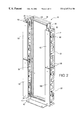
FIG. 17 is a side view of the channel member illustrated in FIG. 15; and
FIG. 18 is a bottom view of the channel member illustrated in FIG. 15.
DETAILED DESCRIPTION OF THE DRAWINGS
Referring to FIGS. 1 and 2, a cable management assembly 10 according to the present invention is illustrated. The assembly 10 comprises a rack 20 having a plurality of Z-channel members 60 mounted thereon with gates 140 mounted on each Z-channel member 60 and covers 180 mounted on gates 140 covering Z-channel members 60.
As seen in FIGS. 1-4, Rack or frame 20 includes a left portion 22 with inner and outer surfaces 24 and 26 and a right portion 28 with inner and outer surfaces 30 and 32. Mating first through holes or support elements 44 for receiving integral clips 100 and 102 of Z-channel member 60, as discussed below, are disposed along both left and right portions 22 and 28. A plurality of mating holes 44 positioned along the length of portions 22 and 28 allow accommodation of different sized channel members. Top bracing portion 34 with outwardly extending support flanges 36 extends between left and right portions 22 and 28. Base portion 38 with outwardly extending support legs 40 extends between left and right portions 22 and 28. Support legs 40 support rack 20 and include holes 42 for receiving bolts for securing rack 20 to the floor. Top bracing portion 34 and base portion 38 are substantially perpendicular to left and right portions 22 and 28. Left and right portions 22 and 28 are typically U-shaped in cross-section and provide an attachment for a plurality of different cross-connect products (not shown) therebetween in central area 46 defined by inner surface 24 of left portion 22, top bracing portion 34, inner surface 30 of right portion, and base portion 38. An example of cross-connect product for attaching to rack 20 is disclosed in U.S. Pat. Ser. No. 5,765,698, which is incorporated herein by reference.
Channel members 60 are mounted on outer surfaces 26 and 32 of left and right portions 22 and 28, respectively. Wires 12 are held and organized in channel members 60 and can be connected to the cross-connect products held in central area 46. Although four channel members 60 are shown, both rack 20 and channel member 60 can be sized such that more or less than four channel members 60 can be used. Rack 20 is preferably made of a metal material but can be formed of any rigid material.
As seen in FIGS. 1-10, Z-channel or channel member 60 includes three elongated planar members, left or first member 62, right or second member 72, and middle member 82. The designations of “left” and “right” are with respect to channel member 60 as shown in FIGS. 8-10 and are for reference purposes only. Left member 62 has inner and outer surfaces 68 and 70, respectively, and a plurality of elongated cutouts 63 that form a plurality of segments 65. A plurality of rear walls or first surfaces 64 extend inwardly from inner surface 68 such that each rear wall 64 extends from each segment 65. Front wall or second surface 66 extends inwardly from inner surface 68 opposite rear walls 64.
Each rear wall 64 and front wall 66 are substantially perpendicular to left member 62. Right or second member 72 has inner and outer surfaces 78 and 80, respectively, and a plurality of elongated cutouts 73 that for a plurality of segments 75 similar to segments 65. A plurality of front walls or fourth surfaces 76 extend inwardly from inner surface 78 such that each front wall 76 extends from each segment 75. Rear wall or third surface 74 extends inwardly from inner surface 78 opposite front walls 76. Rear wall 74 and each front wall 76 are substantially perpendicular to right member 72. Rear walls 64 of left member 62 are substantially planar with rear wall 74 of right member 72. Front wall 66 of left member 62 is substantially planar with front walls 76 of right member 72. Preferably, front wall 66 and rear wall 74 are wider than front walls 76 and rears walls 64, however, they can be of various widths or the same width. Also, four rear walls 64 and four front walls 76 are shown where the two middle walls have a length approximately half of the length of the outer walls, as shown in FIG. 7. However, any number of rear and front walls 64 and 76 with varying lengths depending on the length of Z-channel member 60.
Middle member 82 has left and right surfaces 84 and 86 and extends from front wall 66 to rear wall 74. Middle member 82 connects left member 62 to right member 72 such that the cross section, a section transverse to the longitudinal axis of Z-channel member 60, is Z-shaped, as seen in FIG. 3. First receiving area 90 is defined between left surface 84 of middle member 82 and inner surface 68 of left member 62 and second receiving area 92 is defined between right surface 86 of middle member 82 and inner surface 78 of right member 72. First receiving area 90 has opening 91 that provides access therein for wires 12. Opening 91 is defined by the area between rear walls 64 and rear wall 74. Similarly, second receiving area 92 has opening 93 that provides access therein for wires 12. Opening 93 is defined by the area between front wall 66 and front walls 76.
Apertures 88, each with outer lip 89, are preferably evenly disposed along middle member 82 and provide access for wires 12 between first and second receiving areas 90 and 92. Although shown as generally circular, apertures 88 can be of any shape, such as square or oval. In addition, only one aperture 88 need be employed as long as first receiving area 90 can be accessed by second receiving area 92, and second receiving area 92 can be accessed by first receiving area 90. Wires 12 can be vertically received in both first and second receiving areas 90 and 92 such that one wire 12 can be concurrently received in both first and second receiving areas 90 and 92 through apertures 88, as seen in FIG. 4.
Z-channel member 60 further has top edge 94, bottom edge 96 and beveled side edges 98 connecting middle member 82 to front and rear wall 66 and 74, connecting rear walls 64 and front wall 66 to left member 62, and connecting rear wall 74 and front walls 76 to right member 72. It is preferred that Z-channel member be formed of metal material but it may be formed of a lighter weight material such as plastic.
Top and bottom integral clips, or fastening elements, 100 and 102 are disposed on left member 62 proximate top and bottom edge 94 and 96, respectively. Clips 100 and 102 are formed by punching out a small section of left member 62 and extend outwardly from outer surface 70. Although pairs of clips 100 and 102 are shown, it will be understood that any number of clips 100 and 102 can be used as long as they correspond to mating holes 44 of rack 20. As seen in FIG. 4, clips 100 and 102 are downwardly curved and tapered at the end to create a hook for securely mounting Z-channel member 60 on rack 20. To mount channel member 60 on rack 20, top and bottom clips 100 and 102 are inserted into corresponding mating holes 44 of rack 20 that are sized to accommodate clips 100 and 102 such that bottom surfaces 106 of clips 100 and 102 rest on bottom portions of the mating holes 44 to fully support channel 60 on rack 20. Clips 100 and 102 are sufficiently strong to support any wire attached to channel 60 as well.
Channel member 60 is designed such that the same channel member 60 can be mounted on either left portion 22 or right portion 28 of rack 20. This design reduces costs by requiring only one mold to be used to make channel members 60 eliminating the necessity of two different molds, one to accommodate the left portion 22 and one to accommodate the right portion 28. However, left, right, and middle members 62, 72 and 82 can be formed separately and then connected by any known attachment means.
To mount Z-channel member on right portion 28 of rack 20, top integral clips 100 are inserted into mating holes 44 proximate top bracing portion 34 of rack 20, and bottom integral clips 102 are inserted into mating holes 44 located near a mid-section of rack 20, as seen in FIG. 1. When Z-channel member 60 is mounted on right portion 28, outer surface 70 of left member 62 is adjacent to outer surface 32 of right portion 28, front wall 66 faces frontwardly providing access to second receiving area 92 from the front, and rear wall 74 faces rearwardly providing access to first receiving area 90 from the rear. To mount Z-channel member 60 on left potion 22 of rack 20, Z-channel member 60 must be rotated 180-degrees around its longitudinal axis such that outer surface 70 of left member 62 is adjacent outer surface 26 of left portion 22 of rack 20. Z-channel member 60 is mounted on left portion 22 in the same fashion as described above with respect to right portion 28. When S-channel member 60 is mounted on left portion 22, rear wall 74 faces frontwardly providing access to first receiving area 90 from the front and front wall 66 faces rearwardly providing access to second receiving area 92 from the rear. It will be understood that Z-channel members 60 can be made of various lengths depending on the number of channels desired and the size of rack 20.
As seen in FIG. 7, mating holes, or fastening elements, 108 are located on the right member 72 in locations corresponding to the location of top and bottom clips 100 and 102 on left member 62. Mating or second holes 108 allow more than one channel member 60 to be ganged together by inserting integral clips 100 and 102 of a second channel member 60 (not shown) with the mating holes 108 of a first channel member 60. FIG. 3 shows a second channel member 60 (partially) in dashed lines ganged to another channel 60 shown in solid lines. Upon ganging the first and second channels 60 together, outer surface 80 of right member 72 of the first channel member 60 is adjacent to outer surface 70 of left member 62 of the second channel member. This provides the ability to accommodate more wires using only one rack 20 and a plurality of successively ganged channel members 60. The number of ganged channel members 60 can be determined by the user.
In addition, two or more channel members 60 can be ganged between more than one rack 20 (not shown). Upon mounting a first channel member 60 on right portion 28 of a first rack 20, a second channel member 60 can then be coupled with the first channel member 60 by fastening together corresponding mating holes 108 located on right member 72 of each first and second channel members 60 such that front wall 66 of the first channel member 60 faces forwardly and front wall 66 of the second channel member 60 faces rearwardly. Typically, nut and bolt type fasteners are employed to couple first and second channel members 60 together. This allows second channel member 60 to be coupled with a second rack 20 by inserting clips 100 and 102 of the second channel member 60 into corresponding mating holes 44 of left portion 22 of second rack 20.
Z-channel member includes pairs of first and second slots, or fastening elements, 110 and 112 that are evenly disposed on front wall 66 and rear wall 74. Pairs of slots 110 and 112 are also disposed on each front and rear walls 64 and 76. The location of slots 110 and 112 on front wall 66 correspond to the location of slots 110 and 112 on front walls 76. Similarly, the location of slots 110 and 112 on rear wall 74 correspond to the location of slots 110 and 112 on rear walls 64. Gates, or brackets, 140 can then be received in each corresponding pairs of slots, as seen in FIGS. 5-8. The number of pairs of slots 110 and 112 to be utilized can vary depending on the number of front walls 76 and rear walls 64 employed, however, it will be understood that only two pairs of corresponding slots are necessary. Tongue or engaging elements 114 are also disposed on front wall 66 and rear wall 74 for storing gates 140 and are formed by U-shaped cutouts 115. Although four tongue elements 114 are shown, any number of tongues elements 114 can be used. Elongated slots 116 are vertically disposed on middle member 82 as seen FIGS. 7 and 8. Slots 116 allow straps, typically VELCRO, to be inserted through the slots 116 and wrapped around wires 12, facilitating the bundling and organization of wires 12.
As seen in FIGS. 1-12, cable management assembly 10 includes gates 140 that are mounted on Z-channel member 60 for enclosing wires 12. Gates 140 can be mounted on both the front and the rear of Z-channel member 60. Gate 140 includes left and right end walls 142 and 146 connected to middle wall 154 with an inner and outer perimeter 162 and 164. Each end wall 142 and 146 includes two outwardly extending curved side flanges 148 and first and second foot members 150 and 152 for engaging first and second slots 110 and 112 of Z-channel member 60. Foot members 150 and 152 extend from distal ends 149 of each end wall 142 and 146 by extensions 153 where foot member 150 is adapted to fit first slot 110 and second foot member 152 is adapted to fit second slot 112. Middle wall 154 extends between left and right end walls 142 and 146 connected by curved edges 160 and includes support ribs 158 which are disposed on the inner surface of middle wall 154 and extend the entire length of middle wall 154. Tongue or cover receiving element 156 is centrally located on middle wall 154 and is formed by a U-shaped cutout 157.
As seen in FIG. 5, gate 140 is mounted on Z-channel member 60 by first inserting first foot member 150 into first slot 110 at an angle and subsequently rotating gate 140 downwardly such that second foot member 152 is inserted into second slot 112. Upon being inserted, extensions 153 of each foot member 150 and 152 rest on bottom portions of slots 110 and 112, respectively. Once mounted, gates 140 act to enclose wires 12 in first and second receiving areas 90 and 92 by providing a bracket across openings 91 and 93 of first and second receiving areas 90 and 92, respectively, such that wires 12 are disposed in and between receiving areas 90 and 92 and inner perimeter 162 of gates 140. To remove gate 140 from Z-channel member 60, gate 140 is lifted slightly and rotated upwardly such that second foot member 152 is disengaged from second slot 112, allowing first foot member 150 to be pulled out of engagement with first slot 110.
A lance or hanging element 144 for storing gates 140 onto Z-channel member 60 extends outwardly from left end wall 142. Specifically, lance element 144 engages tongue elements 114 of Z-channel member 60. Lance element 144 is preferably formed by punching out a section from left end member 144, as seen in FIG. 11. Tongue elements 114 allow a plurality of gates 140 to be stored on Z-channel member 60 by hanging each lance element 144 on a corresponding tongue element 114, as seen in FIG. 12. Storage of the gates 140 facilitates the loading, managing, and rearranging of wires 12. Specifically, gates 140 obstruct access to openings 91 and 93 of first and second receiving areas 90 and 92 of Z-channel member 60, thus by removing gates 140 the operator gains easy access to receiving areas 90 and 92 through openings 91 and 93 allowing the operator to load and organize wires 12. In addition, tongue elements 114 provide a convenient place for the operator to store gates 140 while loading and organizing wires 12. Upon completion of loading and organizing wires 12 within first and second areas 90 and 92, the operator needs only to retrieve gates 140 from their storage positions and mount them back onto Z-channel member 60 to hold in wires 12. It will be understood that only one tongue element 114 is necessary and that the entire design of gates 140 eliminates the need for any additional fasteners in either mounting or storing gates 140 on Z-channel member 60 or in receiving cover 180, as discussed below.
Cable management assembly 10 also includes covers 180 for providing enhanced aesthetics mounted to gates 140, as seen in FIGS. 1-14. Cover 180 has a main body portion 182 that is substantially the same length as channel member 60. Main body portion 182 includes left and right sidewalls 186 and 188 connected to main body portion 182 by beveled edge walls 190, and front and back surfaces 192 and 194. Top and bottom lance or mounting elements 196 and 198 are disposed on main body portion 182 and allow easy mounting and removal of cover 180 from gates 140. Lance element 196 is located proximate top end 200 of cover 180 and bottom lance element 198 is located proximate bottom end 202 of cover 180. As seen in FIG. 6, lance elements 196 and 198 engage corresponding tongue elements 156 of gates 140 to mount cover 180 onto gates 140. Specifically, top lance element 196 is hung on tongue element 156 of a first gate 140 and bottom lance element 198 is hung on tongue element 156 of a second gate 140. Lance elements 196 and 198 are preferably formed by punching out a small section of main body portion 182. By forming lance elements integrally with main body portion 182, the need for additional fasteners to mount cover 180 is eliminated thus reducing costs in making and using covers 180.
FIGS. 15-18 show a second embodiment of a channel member to be employed with rack 20, C-channel member 210. C-channel member 210 includes left member 212, right member 222, and middle member 232. Left or first member 212 has front end 214, rear end 216, and inner and outer surfaces 218, 220. Right or second member 222 has front end 224, rear end 226, and inner and outer surfaces 228 and 230. Middle member 232 connects back end 216 of left member 212 and back end 226 of right member 222 such that the cross section, a section transverse to the longitudinal axis of C-channel member 210, is C-shaped. Front wall or surface 234 extends from front end 214 of left member 212 and front end 224 of right member 220 opposite middle member 232. Front walls 234 extend the length of C-channel member 210 and are substantially perpendicular to left and right portions 212 and 222, respectively. Left, right, and middle member 212, 222, and 232 and front walls 234 form an inner receiving area 236 for holding wires 12. Front walls 234 define front opening 238 therebetween where front opening 238 provides access to inner receiving area 228 to load or organize wires 12 therein.
Top and bottom integral clips 240 and 242 are formed in C-channel member in substantially the same fashion as integral clips 100 and 102 as discussed above with respect to Z-channel member 60. In addition, the C-shaped design of C-channel member 210 allows clips 240 and 242 to be disposed on both left and right member 212 and 222 and requires only one mold to form C-channel member 210. Pairs of top clips 240 are disposed on each left and right member 212 and 222 proximate the top of C-channel member 210. Pairs of bottom clips 242 are disposed on each left and right member 212 and 222 proximate the bottom of C-channel member. It will be understood that any number of clips 240 and 242 can be used as long as they correspond to mating holes 44 on rack 20.
C-channel member and clips 240 and 242 engage rack 20 in the same manner as Z-channel member and clips 100 and 102 such that one C-channel member can be mounted on either left or right portion 22 and 28 of rack 20. When mounted in a first position on right portion 28, outer surface 230 of left member 212 is adjacent outer surface 32 of right portion 28 and front opening 238 faces forwardly. When mounted in a second position on left portion 22, outer surface 230 of right member 222 is adjacent outer surface 26 of left member 22 and front opening 238 faces forwardly. Mating holes or fastening elements 244 for providing additional means for securing C-channel member 210 on rack 20, are disposed on left and right members 212 and 222 and correspond to mating holes 44 on rack 20 such that mating holes 44 and mating holes 244 can be coupled using a typical fastener such as a nut and bolt.
Front walls 234 include corresponding pairs of first and second slots 246 and 248 for receiving first and second foot members 150 and 152 of gates 140 in a fashion substantially similar to first and second receiving slots 110 and 112 of S-channel member 60. Gates 140 serve to enclose wires 12 in inner receiving area 236 in the same manner as discussed above with respect to first and second receiving areas 90 and 92 of Z-channel member 60. Slots 246 and 248 are generally evenly dispersed along front walls 234 but can be located anywhere along front walls 234 as long as corresponding pairs of slots are disposed on each front wall 234, respectively. Front walls 234 further include tongue or engaging elements 250 for storing gates 140, in the same fashion as discussed above with respect to tongue elements 114. Tongue elements 250 are also evenly dispersed along front wall 234, however, they can be located anywhere along front walls 234. It will be understood that only one pair of slots 246 and 248 and only one tongue element 250 is necessary for mounting and storing gates 140. Covers 180 can be used with C-channel member 210 in the same manner as discussed above with respect to S-channel member 60.
Middle member 232 includes elongated slots 252 for receiving straps for bundling and managing wires 12 in inner receiving area 236. C-channel is preferable formed of metal material but can be formed of a lighter weight material such as plastic. Also, C-channel 210 and Z-channel 60 can be used together on the same rack 22 or ganged together or used separately.
While a particular embodiment has been chosen to illustrate the invention, it will be understood by those skilled in the art that various changes and modifications can be made therein without departing from the scope of the invention as defined in the appended claims.

Claims (27)

What is claimed is:
1. A channel member for managing wires, comprising:
a first member having a first surface, a second surface, and a plurality of first fastening elements;
an opposing, second member having a third surface, a fourth surface, and a plurality of second fastening elements, said third surface of said second member being planar with said first surface of said first member, and said fourth surface of said second member being planar with said second surface of said first member; and
a middle member connecting said second surface of said first member to said third surface of said second member forming a Z-shaped section transverse to a longitudinal axis of said first and second members, said middle member defining first and second receiving areas between said first and second members and having an aperture for providing access between said first and second receiving areas, whereby a wire can be received concurrently in both said first and second receiving areas.
2. A channel member according to claim 1, wherein
said first member a one-piece, unitary member and said first fastening elements include an integral clip extending from said first member.
3. A channel member according to claim 1, wherein
said second member a one-piece, unitary member and said second fastening elements include a mating hole on said second member.
4. A channel member according to claim 1, wherein
said first fastening elements include a plurality of first and second slots located on said first and second surfaces and said second fastening elements include a plurality of first and second slots located on said third and fourth surfaces.
5. A channel member according to claim 1, wherein
said second surface of said first member includes a hanging element for storing a bracket.
6. A channel member according to claim 5, wherein
said third surface include a hanging element.
7. A channel member according to claim 1, wherein
said middle member includes a plurality of apertures.
8. A channel member according to claim 1, wherein
said middle member includes a plurality of elongated slots for receiving straps.
9. A rack assembly, comprising:
a channel member for managing wires having, a one-piece first member with a first surface, a second surface, and an integral fastening element, an opposing, second member with a third surface and a fourth surface, said third surface of said second member being planar with said first surface of said first member, and said fourth surface of said second member being planar with said second surface of said first member, and a middle member connecting said first member to said second member forming first and second receiving areas between said first and second members; and
a frame for supporting said channel member, said frame having a support element engaging said integral fastening element of said first member to support said channel member adjacent said frame.
10. A rack assembly according to claim 9, wherein
said middle member connects said second surface of said first member to said third surface of said second member forming a Z-shaped section transverse to a longitudinal axis of said first and second members.
11. A rack assembly according to claim 9, wherein
said middle member includes an aperture providing access between said first and second receiving areas, whereby a wire can be received concurrently in both said first and second receiving areas.
12. A rack assembly according to claim 9, wherein
said integral fastening member of said first member is a clip extending from said first member and said support element of said frame is a mating hole receiving said clip.
13. A rack assembly according to claim 12, wherein
said first member includes a plurality of clips and said frame includes a plurality of mating holes.
14. A rack assembly according to claim 9, wherein said second member is a one-piece, unitary member and includes an integral fastening element.
15. A rack assembly according to claim 14, wherein
said integral fastening element of said second member is a mating hole.
16. A rack assembly according to claim 9, wherein
each of said first surface of said first member and said third surface of said second member include a slot for receiving a bracket.
17. A rack assembly according to claim 16, further comprising:
a bracket with opposing ends, said ends engaging said slots of said first and third surfaces.
18. A rack assembly according to claim 17, wherein
said bracket includes a cover receiving element for supporting a cover.
19. A rack assembly according to claim 18, further comprising:
a cover for covering wires within said channel member, said cover having a mounting element, said mounting element engaging said cover receiving element of said bracket to position said cover adjacent said bracket.
20. A rack assembly, comprising:
a first channel member for managing wires having, a one-piece first member with a first surface, a second surface, and an integral first fastening element extending from said first member, an opposing, second member with a third surface, a fourth surface, and a second fastening element for engaging a cooperating first fastening element of a second channel member, said third surface of said second member being planar with said first surface of said first member, and said fourth surface of said second member being planar with said second surface of said first member, and a middle member connecting said first member to said second member forming first and second receiving areas between said first and second members, and having an aperture for providing access between said first and second receiving areas; and
a frame for supporting said first channel member, said frame having a support element engaging said first integral fastening element of said first member to support said first channel member adjacent said frame,
whereby a wire can be received concurrently in both said first and second receiving areas of said first channel member.
21. A rack assembly according to claim 20, further comprising:
a second channel member having a first fastening element and said second fastening element of said first channel member engages said first fastening element of said second channel member whereby said second channel member is positioned adjacent to and supported by said first channel member.
22. A rack assembly according to claim 21, wherein
said support element of said frame is a first hole, said integral first fastening element of said first channel member is a clip extending into said first hole, said second fastening element of said first channel member is a second hole, and said first fastening element of said second channel member is a clip extending into said second hole.
23. A rack assembly according to claim 21, wherein
said first and second channel members are substantially identical.
24. A method for managing wires, comprising the steps of:
providing a bracket having opposing ends and a hanging element, and a channel member having an area for holding wires, fastening elements for receiving the ends of the bracket, and an engaging element for receiving the hanging element of the bracket;
storing the bracket on the channel member in a stored position such that the hanging element of the bracket is coupled to the engaging element of the channel member;
accessing the area for holding wires in the channel member;
removing the bracket from the stored position; and
placing the bracket back on the channel member to hold the wires in the channel member such that the ends of the bracket are engaged with the fastening elements of the channel member.
25. A method for managing wires according to claim 24, further comprising the steps of:
removing the bracket from the channel member by disengaging the ends of the bracket from the fasteners of the channel member;
storing the bracket on the channel member in the stored position;
accessing the area for holding wires in the channel member;
removing the bracket from the stored position; and
placing the bracket back on the channel member to hold the wires in the channel member such that the ends of the bracket are engaged with the fasteners of the channel member.
26. The method for managing wires according to claim 25, wherein
the step of accessing the area for holding the wires in the channel member includes loading wires into to the area.
27. The method for managing wires according to claim 25, wherein the step of accessing the area for holding the wires in the channel member includes rearranging wires in the area.
US09/465,839 1999-12-17 1999-12-17 Vertical cable management system Ceased US6347714B1 (en)

Priority Applications (2)

Application Number Priority Date Filing Date Title
US09/465,839 US6347714B1 (en) 1999-12-17 1999-12-17 Vertical cable management system
US10/241,827 USRE42970E1 (en) 1999-12-17 2002-09-12 Vertical cable management system

Applications Claiming Priority (1)

Application Number Priority Date Filing Date Title
US09/465,839 US6347714B1 (en) 1999-12-17 1999-12-17 Vertical cable management system

Related Child Applications (1)

Application Number Title Priority Date Filing Date
US10/241,827 Reissue USRE42970E1 (en) 1999-12-17 2002-09-12 Vertical cable management system

Publications (1)

Publication Number Publication Date
US6347714B1 true US6347714B1 (en) 2002-02-19

Family

ID=23849373

Family Applications (2)

Application Number Title Priority Date Filing Date
US09/465,839 Ceased US6347714B1 (en) 1999-12-17 1999-12-17 Vertical cable management system
US10/241,827 Expired - Lifetime USRE42970E1 (en) 1999-12-17 2002-09-12 Vertical cable management system

Family Applications After (1)

Application Number Title Priority Date Filing Date
US10/241,827 Expired - Lifetime USRE42970E1 (en) 1999-12-17 2002-09-12 Vertical cable management system

Country Status (1)

Country Link
US (2) US6347714B1 (en)

Cited By (56)

* Cited by examiner, † Cited by third party
Publication number Priority date Publication date Assignee Title
US6489565B1 (en) * 2000-09-15 2002-12-03 Chatsworth Products, Inc. Vertical cable management rack
US6504094B2 (en) * 2000-07-12 2003-01-07 Alcatel Canada Inc. Mounting apparatus for equipment enclosures having cable bend radius control and channel for retaining cable
US6540312B1 (en) * 2000-02-25 2003-04-01 Telica, Inc. Cable guide system
US20040099771A1 (en) * 2002-11-27 2004-05-27 Schloss Rheid J. Raceway system
US20040173545A1 (en) * 2003-03-07 2004-09-09 Canty Mark E. Rack-mountable cable manager
US20050006324A1 (en) * 2003-07-09 2005-01-13 Richards Nancy J. Hinged swing bracket assembly for a rack system
US20050006323A1 (en) * 2003-07-09 2005-01-13 Abby Marjana M. Column network hardware management system
US6870095B1 (en) * 2003-09-29 2005-03-22 Google Inc. Cable management for rack mounted computing system
US20050115737A1 (en) * 2003-12-01 2005-06-02 Levesque Stewart A. Cable management system
US20060103270A1 (en) * 2004-11-17 2006-05-18 American Power Conversion Corporation Equipment enclosure kit and assembly method
US20060162948A1 (en) * 2005-01-21 2006-07-27 Rinderer Eric R Cable management system
US20060213853A1 (en) * 2005-03-24 2006-09-28 Middle Atlantic Products, Inc. Relay rack
US20070099494A1 (en) * 2005-11-02 2007-05-03 Eren Niazi Vertical patch panel
US20080205028A1 (en) * 2007-02-22 2008-08-28 Tellabs Operations, Inc. Stackable cable tray
US20090014614A1 (en) * 2007-07-12 2009-01-15 Panduit Corp. Accessory Bracket
US20090090538A1 (en) * 2007-09-06 2009-04-09 Trent Jones Vertical Cable Manager
US20090090533A1 (en) * 2007-09-06 2009-04-09 Trent Jones Horizontal Cable Manager
US20090224110A1 (en) * 2008-01-07 2009-09-10 Chatsworth Products, Inc. Repositionable shelf-mounted handle spool assembly for cable routing
US20090236117A1 (en) * 2008-01-07 2009-09-24 Chatsworth Products, Inc. Cable management accessories
US20090250422A1 (en) * 2008-04-04 2009-10-08 Target Brands, Inc. Fixture accessories
US20090261211A1 (en) * 2008-04-21 2009-10-22 International Business Machines Corporation Cable Management System
US20090273915A1 (en) * 2008-01-07 2009-11-05 Dean Jr David Lee Apparatus and method for organizing cables in a cabinet
USD611326S1 (en) 2008-01-07 2010-03-09 Chatsworth Products, Inc. Raceway for cable management
US20100085726A1 (en) * 2008-10-02 2010-04-08 Panduit Corp. Universal Expandable Patch Panel Bracket
US20100140422A1 (en) * 2004-03-22 2010-06-10 Panduit Corp. Vertical Cable Manager
US20100200707A1 (en) * 2008-01-07 2010-08-12 Chatsworth Products, Inc. Cable management accessories
USD626817S1 (en) 2008-01-07 2010-11-09 Chatsworth Products, Inc. Accessory bracket for fiber management
US20100290752A1 (en) * 2009-01-27 2010-11-18 Panduit Corp. Vertical cable management system
US20110114575A1 (en) * 2009-11-16 2011-05-19 HONG FU JIN PRECISION INDUSTY (ShenZhen) CO. LTD. Rack enclosure
US20110114576A1 (en) * 2009-11-13 2011-05-19 Hong Fu Jin Precision Industry (Shenzhen) Co., Ltd. Rack enclosure
US20110174534A1 (en) * 2010-01-17 2011-07-21 William Krietzman Horizontal cable manager
US20110180295A1 (en) * 2010-01-17 2011-07-28 Chatsworth Products, Inc. Vertical cable manager
US20120145655A1 (en) * 2008-05-19 2012-06-14 Mcmillan Iii William Seismically hardened two-post electronic equipment rack
US20120152868A1 (en) * 2010-12-15 2012-06-21 Hon Hai Precision Industry Co., Ltd. Cable management apparatus
US8300404B2 (en) 2010-04-15 2012-10-30 Hewlett-Packard Development Company, L.P. Fan holder including cable channels
US8353492B2 (en) 2004-11-17 2013-01-15 American Power Conversion Corporation Equipment enclosure kit and assembly method
US20130148294A1 (en) * 2011-12-13 2013-06-13 Hon Hai Precision Industry Co., Ltd. Server cabinet
FR2989101A1 (en) * 2012-04-06 2013-10-11 Sylvain Daniel Raoul Roger Prefabricated service shaft for use in e.g. service wall, during construction of e.g. individual house, has inner side faces allowing connections between fluid managers and distribution networks and accommodating management equipments
US8787023B2 (en) 2010-09-10 2014-07-22 Chatsworth Products, Inc. Rail mounting clamp for electronic equipment enclosure
US20140206273A1 (en) * 2007-11-19 2014-07-24 Ortronics, Inc. Equipment Rack and Associated Ventilation System
US8901438B2 (en) 2010-09-10 2014-12-02 Chatsworth Products, Inc. Electronic equipment cabinet structure
EP2871505A1 (en) * 2013-11-08 2015-05-13 CCS Technology, Inc. Apparatus for vertically guiding optical waveguide cables and for vertically storing excess lengths of the optical waveguide cable
US9055677B2 (en) 2010-09-10 2015-06-09 Chatsworth Products, Inc. Cable pass-through panel for electronic equipment enclosure
US9119487B2 (en) 2013-09-13 2015-09-01 Target Brands, Inc. Display system
US20150270637A1 (en) * 2014-03-24 2015-09-24 Commscope Technologies Llc Plate for cable connector attachments
US9207420B2 (en) * 2014-04-21 2015-12-08 Priority Electronics Ltd. Enclosure for fiber optic splitter
US9313557B1 (en) * 2012-07-26 2016-04-12 Google Inc. Rack with mounting column
US20160276852A1 (en) * 2012-12-21 2016-09-22 Nathan R. Roberts Improved storage and charging station system for portable electronic devices
US10076050B2 (en) 2012-12-21 2018-09-11 Nathan R. Roberts Storage and charging station system for portable electronic devices
US10084327B2 (en) 2012-12-21 2018-09-25 Nathan R. Roberts Storage and charging station system for portable electronic devices
US10122157B1 (en) 2015-05-14 2018-11-06 Sticnstac, LLC Panel wire support brackets
US10271452B2 (en) * 2016-07-26 2019-04-23 Chatsworth Products, Inc. Features for cable managers and other electronic equipment structures
US10312700B2 (en) * 2012-12-21 2019-06-04 Nathan R. Roberts Storage and charging station system for portable electronic devices
US10638630B2 (en) * 2012-12-21 2020-04-28 Nathan R. Roberts Storage and charging station system for portable electronic devices with side access to power distribution components
US11108216B2 (en) * 2015-05-14 2021-08-31 Sticnstac Llc Panel wire support brackets
US11686911B2 (en) 2020-09-17 2023-06-27 Panduit Corp. Optical distribution and splice frame including enclosures

Families Citing this family (7)

* Cited by examiner, † Cited by third party
Publication number Priority date Publication date Assignee Title
WO2010025855A1 (en) * 2008-09-05 2010-03-11 Adc Gmbh Frame with cable management
US8737090B2 (en) * 2011-05-16 2014-05-27 Delta Electronics, Inc. Rack mounted computer system and cable management mechanism thereof
US9943003B2 (en) 2012-06-25 2018-04-10 Panduit Corp. Electronics cabinet
US9144175B2 (en) 2012-06-25 2015-09-22 Panduit Corp. Electronics cabinet
US8901418B2 (en) 2012-06-25 2014-12-02 Panduit Corp. Server cabinet
US11013140B1 (en) * 2018-09-25 2021-05-18 Amazon Technologies, Inc. Wall-mounted cable housing assemblies
US11319808B2 (en) * 2018-10-12 2022-05-03 Caterpillar Global Mining Equipment Llc Hose retention system for drilling machine

Citations (9)

* Cited by examiner, † Cited by third party
Publication number Priority date Publication date Assignee Title
US4665546A (en) * 1985-03-13 1987-05-12 Reliance Comm/Tec Corporation Modular distribution frame assembly
US5023404A (en) * 1989-09-13 1991-06-11 Johnson Service Company Wiring duct
US5326934A (en) * 1991-07-08 1994-07-05 Communication Integrators Inc. Multi-commodity connectivity system
US5586012A (en) * 1993-10-04 1996-12-17 Homaco, Inc. Vertical organizer comprised of two sections joined together by a splice and secured between two relay racks
US5765698A (en) 1996-09-04 1998-06-16 Hubbell Incorporated Panel assembly with angularly oriented hinges
US5788087A (en) * 1996-03-18 1998-08-04 Ortronics, Inc. Hinged wire management panel assembly
US5867372A (en) * 1997-04-16 1999-02-02 Advanced Optronics Corp. Frame structure for mounting telecommunications equipment
US5921402A (en) * 1998-04-27 1999-07-13 Systems Manufacturing Corporation Cable management track system
US6223909B1 (en) * 1999-02-12 2001-05-01 Adc Telecommunications, Inc. Cable management rack for telecommunications equipment

Family Cites Families (5)

* Cited by examiner, † Cited by third party
Publication number Priority date Publication date Assignee Title
US2921607A (en) * 1957-02-11 1960-01-19 Jack E Caveney Wiring duct
US3968322A (en) * 1971-07-26 1976-07-06 Taylor Industries, Inc. Wiring duct
US3809799A (en) * 1972-09-28 1974-05-07 Taylor Industries Electrical wiring duct with mounting clip
US5902961A (en) * 1997-01-28 1999-05-11 The Siemon Company Cable manager
US6468112B1 (en) * 1999-01-11 2002-10-22 Adc Telecommunications, Inc. Vertical cable management system with ribcage structure

Patent Citations (9)

* Cited by examiner, † Cited by third party
Publication number Priority date Publication date Assignee Title
US4665546A (en) * 1985-03-13 1987-05-12 Reliance Comm/Tec Corporation Modular distribution frame assembly
US5023404A (en) * 1989-09-13 1991-06-11 Johnson Service Company Wiring duct
US5326934A (en) * 1991-07-08 1994-07-05 Communication Integrators Inc. Multi-commodity connectivity system
US5586012A (en) * 1993-10-04 1996-12-17 Homaco, Inc. Vertical organizer comprised of two sections joined together by a splice and secured between two relay racks
US5788087A (en) * 1996-03-18 1998-08-04 Ortronics, Inc. Hinged wire management panel assembly
US5765698A (en) 1996-09-04 1998-06-16 Hubbell Incorporated Panel assembly with angularly oriented hinges
US5867372A (en) * 1997-04-16 1999-02-02 Advanced Optronics Corp. Frame structure for mounting telecommunications equipment
US5921402A (en) * 1998-04-27 1999-07-13 Systems Manufacturing Corporation Cable management track system
US6223909B1 (en) * 1999-02-12 2001-05-01 Adc Telecommunications, Inc. Cable management rack for telecommunications equipment

Non-Patent Citations (1)

* Cited by examiner, † Cited by third party
Title
Hubbell Premise Wiring Catalog, prior to Dec., 1999, pp. 1, 90, 92-94 and 106.

Cited By (151)

* Cited by examiner, † Cited by third party
Publication number Priority date Publication date Assignee Title
US6540312B1 (en) * 2000-02-25 2003-04-01 Telica, Inc. Cable guide system
US6504094B2 (en) * 2000-07-12 2003-01-07 Alcatel Canada Inc. Mounting apparatus for equipment enclosures having cable bend radius control and channel for retaining cable
US6489565B1 (en) * 2000-09-15 2002-12-03 Chatsworth Products, Inc. Vertical cable management rack
US6605782B1 (en) * 2000-09-15 2003-08-12 Chatsworth Products, Inc. Vertical cable management rack
US20040007372A1 (en) * 2000-09-15 2004-01-15 Chatsworth Products, Inc. Vertical cable management rack
US7119282B2 (en) 2000-09-15 2006-10-10 Chatsworth Products, Inc. Vertical cable management rack
US20040099771A1 (en) * 2002-11-27 2004-05-27 Schloss Rheid J. Raceway system
US7229050B2 (en) * 2002-11-27 2007-06-12 Hewlett-Packard Development Company, L.P. Raceway system
US20040173545A1 (en) * 2003-03-07 2004-09-09 Canty Mark E. Rack-mountable cable manager
US7000784B2 (en) 2003-03-07 2006-02-21 Panduit Corp. Rack-mountable cable manager
US20060091086A1 (en) * 2003-03-07 2006-05-04 Canty Mark E Rack-mountable cable manager
US7378046B2 (en) 2003-03-07 2008-05-27 Panduit Corp. Method of molding rack-mountable cable manager
US20070007411A1 (en) * 2003-07-09 2007-01-11 Richards Nancy J Hinged swing bracket assembly for rack system
US7121412B2 (en) 2003-07-09 2006-10-17 Hubbell Incorporated Hinged swing bracket assembly for a rack system
US20050006324A1 (en) * 2003-07-09 2005-01-13 Richards Nancy J. Hinged swing bracket assembly for a rack system
US20050006323A1 (en) * 2003-07-09 2005-01-13 Abby Marjana M. Column network hardware management system
US20070114193A1 (en) * 2003-07-09 2007-05-24 Hubbell Incorporated Column network hardware management system
US7172078B2 (en) 2003-07-09 2007-02-06 Hubbell Incorporated Column network hardware management system
US7828156B2 (en) * 2003-07-09 2010-11-09 Hubbell Incorporated Column network hardware management system
US6870095B1 (en) * 2003-09-29 2005-03-22 Google Inc. Cable management for rack mounted computing system
US7026553B2 (en) 2003-12-01 2006-04-11 Ortronics, Inc. Cable management system
US20050115737A1 (en) * 2003-12-01 2005-06-02 Levesque Stewart A. Cable management system
US6946605B2 (en) 2003-12-01 2005-09-20 Ortronics, Inc. Cable management system
WO2005061937A1 (en) * 2003-12-01 2005-07-07 Ortronics, Inc. Cable management system
US20050115736A1 (en) * 2003-12-01 2005-06-02 Levesque Stewart A. Cable management system
US20100140422A1 (en) * 2004-03-22 2010-06-10 Panduit Corp. Vertical Cable Manager
US7857670B2 (en) 2004-03-22 2010-12-28 Panduit Corp. Vertical cable manager
US20110068233A1 (en) * 2004-03-22 2011-03-24 Panduit Corp. Vertical Cable Manager
US8435086B2 (en) 2004-03-22 2013-05-07 Panduit Corp. Vertical cable manager
US8162699B2 (en) 2004-03-22 2012-04-24 Panduit Corp. Vertical cable manager
US8353492B2 (en) 2004-11-17 2013-01-15 American Power Conversion Corporation Equipment enclosure kit and assembly method
US8528872B2 (en) 2004-11-17 2013-09-10 Schneider Electric It Corporation Equipment enclosure kit and assembly method
US7472970B2 (en) * 2004-11-17 2009-01-06 American Power Conversion Corporation Equipment enclosure kit and assembly method
US20060103270A1 (en) * 2004-11-17 2006-05-18 American Power Conversion Corporation Equipment enclosure kit and assembly method
US20060162948A1 (en) * 2005-01-21 2006-07-27 Rinderer Eric R Cable management system
US20080130262A1 (en) * 2005-01-21 2008-06-05 Cooper Technologies Company Cable management system
US7778513B2 (en) 2005-01-21 2010-08-17 Cooper Technologies Company Cable manager with adjustable cable guides
US7219809B2 (en) * 2005-03-24 2007-05-22 Middle Atlantic Products, Inc. Relay rack
US20060213853A1 (en) * 2005-03-24 2006-09-28 Middle Atlantic Products, Inc. Relay rack
US20070099494A1 (en) * 2005-11-02 2007-05-03 Eren Niazi Vertical patch panel
US8605459B2 (en) * 2007-02-22 2013-12-10 Tellabs Operations, Inc. Stackable cable tray
US7916502B2 (en) * 2007-02-22 2011-03-29 Tellabs Operations, Inc. Stackable cable tray
US20080233858A1 (en) * 2007-02-22 2008-09-25 Tellabs Operations, Inc. Apparatus, system, and method for venting a chassis
US20110132855A1 (en) * 2007-02-22 2011-06-09 Tellabs Operations, Inc. Stackable cable tray
US8944896B2 (en) 2007-02-22 2015-02-03 Tellabs Operations, Inc. Apparatus, system, and method for venting a chassis
US20080205028A1 (en) * 2007-02-22 2008-08-28 Tellabs Operations, Inc. Stackable cable tray
US9038973B2 (en) 2007-07-12 2015-05-26 Panduit Corp. Accessory bracket
US20090014614A1 (en) * 2007-07-12 2009-01-15 Panduit Corp. Accessory Bracket
US7939763B2 (en) 2007-09-06 2011-05-10 Hoffman Enclosures, Inc. Horizontal cable manager
US20090090538A1 (en) * 2007-09-06 2009-04-09 Trent Jones Vertical Cable Manager
US20090090533A1 (en) * 2007-09-06 2009-04-09 Trent Jones Horizontal Cable Manager
US7973242B2 (en) 2007-09-06 2011-07-05 Hoffman Enclosures, Inc. Vertical cable manager
US20150118950A1 (en) * 2007-11-19 2015-04-30 Ortronics, Inc. Equipment Rack and Associated Ventilation System
US9345172B2 (en) * 2007-11-19 2016-05-17 Ortronics, Inc. Equipment rack and associated ventilation system
US20140206273A1 (en) * 2007-11-19 2014-07-24 Ortronics, Inc. Equipment Rack and Associated Ventilation System
US7974105B2 (en) 2008-01-07 2011-07-05 Chatsworth Products, Inc. Apparatus and method for organizing cables in a cabinet
US7999183B2 (en) 2008-01-07 2011-08-16 Chatsworth Products, Inc. Cable management accessories
US8263867B2 (en) 2008-01-07 2012-09-11 Chatsworth Products, Inc. Cable management accessories
US7893356B2 (en) 2008-01-07 2011-02-22 Chatsworth Products, Inc. Cable management accessories
USD611326S1 (en) 2008-01-07 2010-03-09 Chatsworth Products, Inc. Raceway for cable management
US20090273915A1 (en) * 2008-01-07 2009-11-05 Dean Jr David Lee Apparatus and method for organizing cables in a cabinet
US20100122830A1 (en) * 2008-01-07 2010-05-20 Chatsworth Products, Inc. Cable management accessories
US20100126751A1 (en) * 2008-01-07 2010-05-27 Chatsworth Products, Inc. Cable management accessories
US20100200707A1 (en) * 2008-01-07 2010-08-12 Chatsworth Products, Inc. Cable management accessories
US8437147B2 (en) 2008-01-07 2013-05-07 Chatsworth Products, Inc. Kit for organizing cables in a cabinet
US20090236117A1 (en) * 2008-01-07 2009-09-24 Chatsworth Products, Inc. Cable management accessories
US20100101820A1 (en) * 2008-01-07 2010-04-29 Chatsworth Products, Inc. Cable management accessories
US8003890B2 (en) 2008-01-07 2011-08-23 Chatsworth Products, Inc. Repositionable shelf-mounted handle spool assembly for cable routing
US20110211328A1 (en) * 2008-01-07 2011-09-01 Chatsworth Products, Inc. Apparatus and method for organizing cables in a cabinet
US20110211329A1 (en) * 2008-01-07 2011-09-01 Chatsworth Products, Inc. Apparatus and method for organizing cables in a cabinet
US8411465B2 (en) 2008-01-07 2013-04-02 Chatsworth Products, Inc. Method for organizing cables in a cabinet to reduce impeded airflow
US20090224110A1 (en) * 2008-01-07 2009-09-10 Chatsworth Products, Inc. Repositionable shelf-mounted handle spool assembly for cable routing
US8138419B2 (en) 2008-01-07 2012-03-20 Chatsworth Products, Inc. Cable management accessories
US20100126750A1 (en) * 2008-01-07 2010-05-27 Chatsworth Products, Inc. Cable management accessories
USD626817S1 (en) 2008-01-07 2010-11-09 Chatsworth Products, Inc. Accessory bracket for fiber management
US8330043B2 (en) 2008-01-07 2012-12-11 Chatsworth Products, Inc. Cable management accessories
US8273989B2 (en) 2008-01-07 2012-09-25 Chatsworth Products, Inc. Cable management accessories
US8191720B2 (en) 2008-04-04 2012-06-05 Target Brands, Inc. Method of assembling fixture accessories
US20090250422A1 (en) * 2008-04-04 2009-10-08 Target Brands, Inc. Fixture accessories
US7946435B2 (en) * 2008-04-04 2011-05-24 Target Brands, Inc. Fixture accessories
US8434630B2 (en) 2008-04-04 2013-05-07 Target Brands, Inc. Merchandising system and method of assembly
US20110209329A1 (en) * 2008-04-04 2011-09-01 Target Brands, Inc. Fixture Accessories
US20090261211A1 (en) * 2008-04-21 2009-10-22 International Business Machines Corporation Cable Management System
US20120145655A1 (en) * 2008-05-19 2012-06-14 Mcmillan Iii William Seismically hardened two-post electronic equipment rack
US8424691B2 (en) * 2008-05-19 2013-04-23 Chatsworth Products, Inc. Seismically hardened two-post electronic equipment rack
US8040693B2 (en) 2008-10-02 2011-10-18 Panduit Corp. Universal expandable patch panel bracket
US20100085726A1 (en) * 2008-10-02 2010-04-08 Panduit Corp. Universal Expandable Patch Panel Bracket
US8363998B2 (en) 2009-01-27 2013-01-29 Panduit Corp. Vertical cable management system
US20100290752A1 (en) * 2009-01-27 2010-11-18 Panduit Corp. Vertical cable management system
US20110114576A1 (en) * 2009-11-13 2011-05-19 Hong Fu Jin Precision Industry (Shenzhen) Co., Ltd. Rack enclosure
US20110114575A1 (en) * 2009-11-16 2011-05-19 HONG FU JIN PRECISION INDUSTY (ShenZhen) CO. LTD. Rack enclosure
US10320163B2 (en) 2010-01-17 2019-06-11 Chatsworth Products, Inc. Vertical cable manager
US9899812B2 (en) 2010-01-17 2018-02-20 Chatsworth Products, Inc. Vertical cable manager
US8558113B2 (en) 2010-01-17 2013-10-15 Chatsworth Products, Inc. Vertical cable manager
US8710369B2 (en) 2010-01-17 2014-04-29 Chatsworth Products, Inc. Horizontal cable manager
US9814150B2 (en) 2010-01-17 2017-11-07 Chatsworth Products, Inc. Mounting fixture system
US9577414B2 (en) 2010-01-17 2017-02-21 Chatsworth Products, Inc. Vertical cable manager
US9270097B2 (en) 2010-01-17 2016-02-23 Chatsworth Products, Inc. Horizontal cable manager
US9350146B2 (en) 2010-01-17 2016-05-24 Chatsworth Products, Inc. Vertical cable manager
US11133656B2 (en) 2010-01-17 2021-09-28 Chatsworth Products, Inc. Vertical cable manager
US20110174534A1 (en) * 2010-01-17 2011-07-21 William Krietzman Horizontal cable manager
US20110180295A1 (en) * 2010-01-17 2011-07-28 Chatsworth Products, Inc. Vertical cable manager
US9054506B2 (en) 2010-01-17 2015-06-09 Chatsworth Products, Inc. Vertical cable manager
US8300404B2 (en) 2010-04-15 2012-10-30 Hewlett-Packard Development Company, L.P. Fan holder including cable channels
US9642270B2 (en) 2010-09-10 2017-05-02 Chatsworth Products, Inc. Rail seal for electronic equipment enclosure
US10588227B2 (en) 2010-09-10 2020-03-10 Chatsworth Products, Inc. Vertical mounting rail with cable management features
US11792948B2 (en) 2010-09-10 2023-10-17 Chatsworth Products, Inc. Cable pass-through panel for electronic equipment enclosure
US11464123B2 (en) 2010-09-10 2022-10-04 Chatsworth Products, Inc. Method of adapting an electronic equipment enclosure for cable management
US9055677B2 (en) 2010-09-10 2015-06-09 Chatsworth Products, Inc. Cable pass-through panel for electronic equipment enclosure
US11039543B2 (en) 2010-09-10 2021-06-15 Chatsworth Products, Inc. Vertical mounting rail with cable management features
US10653025B2 (en) 2010-09-10 2020-05-12 Chatsworth Products, Inc. Cable pass-through panel for electronic equipment enclosure
US8901438B2 (en) 2010-09-10 2014-12-02 Chatsworth Products, Inc. Electronic equipment cabinet structure
US9408326B2 (en) 2010-09-10 2016-08-02 Chatsworth Products, Inc. Electronic equipment cabinet structure
US9814159B2 (en) 2010-09-10 2017-11-07 Chatsworth Products, Inc. Rail seal for electronic equipment enclosure
US8787023B2 (en) 2010-09-10 2014-07-22 Chatsworth Products, Inc. Rail mounting clamp for electronic equipment enclosure
US9980400B2 (en) 2010-09-10 2018-05-22 Chatsworth Products, Inc. Rail seal for electronic equipment enclosure
US10237994B2 (en) 2010-09-10 2019-03-19 Chatsworth Products, Inc. Vertical mounting rail with cable management features
US10178784B2 (en) 2010-09-10 2019-01-08 Chatsworth Products, Inc. Rail seal for electronic equipment enclosure
US9781852B2 (en) 2010-09-10 2017-10-03 Chatsworth Products, Inc. Cable pass-through panel for electronic equipment enclosure
US20120152868A1 (en) * 2010-12-15 2012-06-21 Hon Hai Precision Industry Co., Ltd. Cable management apparatus
US8593829B2 (en) * 2010-12-15 2013-11-26 Hong Fu Jin Precision Industry (Shenzhen) Co., Ltd. Cable management apparatus
US20130148294A1 (en) * 2011-12-13 2013-06-13 Hon Hai Precision Industry Co., Ltd. Server cabinet
US8717767B2 (en) * 2011-12-13 2014-05-06 Hong Fu Jin Precision Industry (Shenzhen) Co., Ltd. Server cabinet
FR2989101A1 (en) * 2012-04-06 2013-10-11 Sylvain Daniel Raoul Roger Prefabricated service shaft for use in e.g. service wall, during construction of e.g. individual house, has inner side faces allowing connections between fluid managers and distribution networks and accommodating management equipments
US9313557B1 (en) * 2012-07-26 2016-04-12 Google Inc. Rack with mounting column
US9680317B2 (en) * 2012-12-21 2017-06-13 Nathan R. Roberts Storage and charging station system for portable electronic devices
US10312700B2 (en) * 2012-12-21 2019-06-04 Nathan R. Roberts Storage and charging station system for portable electronic devices
US20160276852A1 (en) * 2012-12-21 2016-09-22 Nathan R. Roberts Improved storage and charging station system for portable electronic devices
US10638630B2 (en) * 2012-12-21 2020-04-28 Nathan R. Roberts Storage and charging station system for portable electronic devices with side access to power distribution components
US10084327B2 (en) 2012-12-21 2018-09-25 Nathan R. Roberts Storage and charging station system for portable electronic devices
US10076050B2 (en) 2012-12-21 2018-09-11 Nathan R. Roberts Storage and charging station system for portable electronic devices
US9119487B2 (en) 2013-09-13 2015-09-01 Target Brands, Inc. Display system
EP2871505A1 (en) * 2013-11-08 2015-05-13 CCS Technology, Inc. Apparatus for vertically guiding optical waveguide cables and for vertically storing excess lengths of the optical waveguide cable
US9660397B2 (en) * 2014-03-24 2017-05-23 Commscope Technologies Llc Plate for cable connector attachments
US20150270637A1 (en) * 2014-03-24 2015-09-24 Commscope Technologies Llc Plate for cable connector attachments
US9207420B2 (en) * 2014-04-21 2015-12-08 Priority Electronics Ltd. Enclosure for fiber optic splitter
US10122157B1 (en) 2015-05-14 2018-11-06 Sticnstac, LLC Panel wire support brackets
US11108216B2 (en) * 2015-05-14 2021-08-31 Sticnstac Llc Panel wire support brackets
US11071227B2 (en) 2016-07-26 2021-07-20 Chatsworth Products, Inc. Accessory rod assembly for a cable manager
US11162615B2 (en) 2016-07-26 2021-11-02 Chatsworth Products, Inc. Features for cable managers and other electronic equipment structures
US11268636B2 (en) 2016-07-26 2022-03-08 Chatsworth Products, Inc. Features for cable managers and other electronic equipment structures
US10477720B2 (en) 2016-07-26 2019-11-12 Chatsworth Products, Inc. Features for cable managers and other electronic equipment structures
US11493151B2 (en) 2016-07-26 2022-11-08 Chatsworth Products, Inc. Features for cable managers and other electronic equipment structures
US11619328B2 (en) 2016-07-26 2023-04-04 Chatsworth Products, Inc. Method of adapting electronic equipment structure for cable management
US11644126B2 (en) 2016-07-26 2023-05-09 Chatsworth Products, Inc. Method of installing half-spool accessory in a cable manager
US11644125B2 (en) 2016-07-26 2023-05-09 Chatsworth Products, Inc. Method of installing cable finger accessory in a cable manager
US10271452B2 (en) * 2016-07-26 2019-04-23 Chatsworth Products, Inc. Features for cable managers and other electronic equipment structures
US11815197B2 (en) 2016-07-26 2023-11-14 Chatsworth Products, Inc. Features for cable managers and other electronic equipment structures
US11686911B2 (en) 2020-09-17 2023-06-27 Panduit Corp. Optical distribution and splice frame including enclosures
US11921339B2 (en) 2020-09-17 2024-03-05 Panduit Corp. Optical distribution and splice frame including vertical cable managers
US11947178B2 (en) 2020-09-17 2024-04-02 Panduit Corp. Optical distribution and splice frame including cassettes

Also Published As

Publication number Publication date
USRE42970E1 (en) 2011-11-29

Similar Documents

Publication Publication Date Title
US6347714B1 (en) Vertical cable management system
US11133656B2 (en) Vertical cable manager
US6353696B1 (en) Panel for managing jumper storage
AU759139C (en) Vertical cable management system with ribcage structure
US5743416A (en) Tool rack
US7298951B2 (en) Cable management device and method
US6418671B1 (en) Wall panel system
JP5636376B2 (en) Vertical cable management system
US20040113024A1 (en) Cable support system
US20010036351A1 (en) Fiber optic wall mount cabinet
CA2344713C (en) Self-securing raceway end cap
IL125445A (en) Optical fibre distribution system
CN113161955A (en) Cable management device
JP2003124657A (en) Cable receiving unit
EP0644440A2 (en) Cable management system
JP3580351B2 (en) Wire bundle stock table
JP3052039U (en) Multiple racks that hold drawer containers in multiple stages
JP3543074B2 (en) Optical fiber holding member and optical wiring rack
JPH0898721A (en) Wiring duct device of furniture

Legal Events

Date Code Title Description
AS Assignment

Owner name: HUBBELL INCORPORATED, CONNECTICUT

Free format text: ASSIGNMENT OF ASSIGNORS INTEREST;ASSIGNORS:FOURNIER, STEVEN O.;SOBIESKI, WILLIAM G.;BAXTER, ROBERT C.;REEL/FRAME:010474/0196

Effective date: 19991217

FEPP Fee payment procedure

Free format text: PAYOR NUMBER ASSIGNED (ORIGINAL EVENT CODE: ASPN); ENTITY STATUS OF PATENT OWNER: LARGE ENTITY

STCF Information on status: patent grant

Free format text: PATENTED CASE

RF Reissue application filed

Effective date: 20020912

FPAY Fee payment

Year of fee payment: 4

FPAY Fee payment

Year of fee payment: 8