US6335601B1 - Wiper control device - Google Patents
Wiper control device Download PDFInfo
- Publication number
- US6335601B1 US6335601B1 US09/615,698 US61569800A US6335601B1 US 6335601 B1 US6335601 B1 US 6335601B1 US 61569800 A US61569800 A US 61569800A US 6335601 B1 US6335601 B1 US 6335601B1
- Authority
- US
- United States
- Prior art keywords
- wiper
- low
- speed
- switch
- motor
- Prior art date
- Legal status (The legal status is an assumption and is not a legal conclusion. Google has not performed a legal analysis and makes no representation as to the accuracy of the status listed.)
- Expired - Lifetime
Links
- 238000012544 monitoring process Methods 0.000 claims description 28
- 239000003990 capacitor Substances 0.000 claims description 14
- 230000008034 disappearance Effects 0.000 claims description 8
- 239000011521 glass Substances 0.000 description 10
- 238000010586 diagram Methods 0.000 description 6
- 230000001105 regulatory effect Effects 0.000 description 5
- 230000010355 oscillation Effects 0.000 description 4
- 230000015572 biosynthetic process Effects 0.000 description 3
- 239000004020 conductor Substances 0.000 description 2
- 238000000926 separation method Methods 0.000 description 2
- 230000003068 static effect Effects 0.000 description 2
- 230000000007 visual effect Effects 0.000 description 2
- 244000145845 chattering Species 0.000 description 1
- 230000001276 controlling effect Effects 0.000 description 1
- 238000001514 detection method Methods 0.000 description 1
- 239000000428 dust Substances 0.000 description 1
- 230000000694 effects Effects 0.000 description 1
- 239000007788 liquid Substances 0.000 description 1
- 230000003534 oscillatory effect Effects 0.000 description 1
Images


Classifications
-
- B—PERFORMING OPERATIONS; TRANSPORTING
- B60—VEHICLES IN GENERAL
- B60S—SERVICING, CLEANING, REPAIRING, SUPPORTING, LIFTING, OR MANOEUVRING OF VEHICLES, NOT OTHERWISE PROVIDED FOR
- B60S1/00—Cleaning of vehicles
- B60S1/02—Cleaning windscreens, windows or optical devices
- B60S1/04—Wipers or the like, e.g. scrapers
- B60S1/06—Wipers or the like, e.g. scrapers characterised by the drive
- B60S1/08—Wipers or the like, e.g. scrapers characterised by the drive electrically driven
Definitions
- This invention relates to a wiper control device for actuating a wiper device mounted, for example on a motor vehicle and especially to a device for controlling the wiper device which is so designed as to change the rotational direction of the wiper motor between cases of high-speed operation and low-speed operation of the motor and decrease substantial length of a motor arm of the wiper linkage at the time of the high speed operation as compared with that of the motor arm at the time of the low speed operation through an arm-length adjusting device including an eccentric mechanism attached on the motor arm of the linkage in order to solve a difference in the wiping ranges at the time of high speed operation and low speed operation caused by a difference of inertial force of the wiper blade.
- wiper apparatuses As an apparatus for wiping rain drops adhering to the windshield of the motor vehicle and ensuring the wide visual range of a driver, wiper apparatuses having various structure and function have been used. Recently, a wiper apparatus which is designed so as to be possible to select working speed of the wiper blade between continuous operation of two-level at high and low speeds and intermittent operation at a low speed according to the amount of rain-fall is used generally.
- the windshield partially remains unwiped and the visual field becomes narrow at the time of low speed operation in a case where the wiping range of the windshield is set on basis of the oscillation range of the wiper blade at the time of high speed operation and the wiper blade runs out of the windshield glass at the time of high speed operation in a case where the wiping range of the windshield is set on basis of the oscillation range of the wiper blade at the time of high speed operation.
- Applicant proposed previously a wiper linkage which was so designed as to solve the difference in the actual wiping range enlarged owing to addition of the inertial force of the wiper blade by setting the rotational direction of the wiper motor at the time of high speed operation conversely against that of the wiper motor at the time of low speed operation, making the substantial length of the motor arm of the wiper linkage at the time of high speed operation shorter than that of the motor arm at the time of low speed operation through an arm length adjusting mechanism attached to the motor arm and used with an eccentric bush to be turned as much as 180° at the time of switching over the rotational direction of the motor arm and reducing the structural wiping range of the wiper blade at the time of high speed operation as compared with that of the wiper blade at the time of low speed operation in Japanese Patent Application No.10-158026/98 in order to remove the difference in the wiping range caused by the difference in the operation speed of the wiper blade in the conventional wiper apparatus of the two-speed type.
- This invention is made in view of the aforementioned problem in the control of the wiper linkage of which wiper motor is different in the rotational direction between low speed operation and high speed operation, and it is an object to provide a wiper control device which is possible to smoothly switch over the rotational direction of the wiper motor together with the rotational speed and execute the control without causing the strange impression and the unwiped area at the time of changing the operation speed and stopping the wiper blade.
- the wiper control device is provided with a wiper switch, a wiper motor, a position switch, a controller and a motor driving circuit, and the controller is so designed as to change the rotational direction of the wiper motor at the time when the wiper blade arrives in the lower turning position or the upper turning position after the low-speed command signal or the high-speed command signal generated from the wiper switch is switched over into the high-speed command signal or the low-speed command signal, respectively.
- the rotation of the wiper motor is switched over from the low-speed forward rotation to the high-speed reverse rotation, or from the high-speed reverse rotation to the low-speed forward direction when the wiper blade arrives at either the lower turning position or the upper turning position, that is when the wiper linkage is in the dead point, therefore the unnatural phenomenon is solved in that the wiper blade goes back at the middle of the windshield glass according as the rotational direction of the wiper motor is changed.
- the position switch is provided with a high-potential plate connected with the power source, a low-potential plate grounded, a clutch member rotatable by being pushed against a push member rotating together with the output shaft of the wiper motor only in a direction energized by the push member, and a movable contact attached to the clutch member so as to slidingly come in contact with the high and low-potential plates.
- the movable contact is not secured to the output shaft of the wiper motor and the wiper blade and so structured as to stay in the present position while the output shaft of the wiper motor makes nearly one revolution in a case where the wiper blade moves backward, or the rotational direction of the wiper motor is changed.
- the chattering of the wiper blade caused by obstacles such snows, and the signal change is obtained suitably for reversing control of the wiper motor from the movable contact by setting the openings between the high and low-potential plates in correspondence to the upper and lower turning positions of the wiper blade, respectively.
- the motor driving circuit forms a current supplying circuit through the movable contact and the low-potential plate of the position switch when the controller does not generate neither the low-speed driving signal nor the high-speed driving signal, and the wiper motor is supplied with an electric current in the low-speed forward-rotational direction through the current supplying circuit while the movable contact is in contact with the low-potential plate of the position switch. Therefore, the wiper blade stops automatically in the predetermined position in response to disappearance of the low-speed driving signal and the high-speed driving signal after off-operation of the wiper switch.
- the position switch is set so as to produce a change in the position signal at the time when the wiper blade arrives at a position predetermined in just before the lower turning position, therefore improper behavior is solved in that the wiper blade stops after passing the lower turning position (home position) by inertia, or moves backward on the windshield glass by the inverting rotation of the wiper motor after passing through the lower turning position.
- the changeover of wiper mode from the low-speed mode to the high-speed mode is carried out speedily by switching over the rotation of the wiper motor into the high-speed reverse rotation from the low-speed forward rotation at the time when the wiper blade is in the upper turning position.
- the device is further provided with a circuit for supplying the position signal on low level to the controller when the movable contact arrives in an opening formed between the high and low-potential plates of the position switch in a case where the controller outputs the high-speed driving signal, and supplying the position signal on high level to the controller when the movable contact arrives in the opening formed between the high and low-potential plates in a case where the controller does not output the high-speed driving signal.
- the controller recognizes the opening to be the high-potential plate at the time of low speed operation and recognizes the opening to be the low-potential plate at the time of high speed operation, and the change is caused in the position signal at the time when the wiper blade arrives at the position predetermined in just before the turning position regardless of the operation speed or the rotational direction of the wiper motor, so that the wiper blade turns accurately at the turning position and stops accurately at the lower turning position without passing the turning position by inertia.
- the controller is so designed as to interrupt the output of the high-speed driving signal at the time when the wiper blade arrives at a position predetermined in just before the lower turning position after disappearance of the high-speed command signal from the wiper switch. Accordingly, time required for the wiper blade to be stopped automatically in the home position (lower turning position) after off-operation of the wiper switch is reduced since the wiper mode remains in the high-speed mode until the wiper motor begins to rotate in the forward direction at the low speed through the current supplying circuit after arrival of the wiper blade in the lower turning position.
- the controller switches over the low-speed driving signal into the high-speed driving signal at the time when the wiper blade arrives at a predetermined position just before the lower turning position or the upper turning position after the low-speed command signal from the wiper switch is changed into the high-speed command signal, and the controller interrupts the output of the high-speed driving signal at the time when the wiper blade arrives at the predetermined position just before the lower turning position after the high-speed command signal from the wiper switch is changed into the low-speed command signal and generates the low-speed driving signal at the time when a period of time predetermined sufficiently longer than time required for the movable contact to pass the opening formed between the high and low-potential plates of the position switch elapses after the arrival of the wiper blade at the predetermined position just before the lower turning position.
- the wiper mode is speedily switched because the driving signal is changed not only when the wiper blade arrives in the position just before the lower turning position, but also when it arrives in the position just before the upper turning position.
- the high-speed driving signal is interrupted first when the wiper blade arrives in the position just before the lower turning position, and then the low-speed driving signal is supplied after the movable contact passes completely through the opening existing between the high and low-potential plates of the position switch, therefore a large electric current does not flow in the relays even when the rotational direction of the wiper motor is changed, whereby load of the relays is lightened and reliability of the relays is improved.
- the backup circuit is so designed as to supply an electric current to the wiper motor in the low-speed forward-rotational direction or the high-speed reverse-rotational direction through the motor driving circuit in accordance with operation of the wiper switch at the time when a watchdog signal becomes extinct by failure of the controller. Therefore it is possible to relieve the serious situation in that the wiper blade falls completely to a standstill even if the controller breaks down unexpectedly owing to some reason.
- the wiper motor is provided with a first terminal connected to a common brush, a second terminal connected to a low brush and a third terminal connected to a high brush
- the motor driving circuit is provided with four relays, first and second transistors of which emitters are grounded and bases are connected to a high-speed driving signal output port and a low-speed driving signal output port of the controller, respectively; ends of respective relay coils of the four relays are connected with the power source, the other ends of the respective relay coils of the first, second and third relays among the four relays are connected to the collector of the first transistor, another end of the relay coil of the fourth relay of the four relays is connected to the collector of the second transistor; a moving contact and a normal-closed contact of the first relay are connected to the power source and the second terminal of the wiper motor, respectively; a moving contact of the second relay is grounded and a normal-closed contact of the second relay is connected to the third terminal of the wiper motor;
- the second transistor is turned to the on-state according to the output of a high-level signal (low-speed driving signal) from the low-speed driving signal output port of the controller, and an electric current is supplied to the wiper motor from the second terminal (low brush) to the first terminal (common brush) through the fourth relay switched on, thereby rotating the wiper motor in the forward direction in the low speed.
- the first transistor is turned to the on-state according to the output of a high-level signal (high-speed driving signal) from the high-speed driving signal output port of the controller, and an electric current is supplied to the wiper motor from the third terminal (high brush) to the first terminal (common brush) through the first, second and third relays switched on, thereby rotating the wiper motor in the reverse direction in the high speed.
- a high-level signal high-speed driving signal
- the wiper motor continues to rotate in the forward direction at the low speed by forming the current supplying circuit during the movable contact of the position switch is on the low-potential plate grounded, and the wiper motor is stopped by forming an armature short circuit when the movable contact comes in contact with the high-potential plate after separating from the low-potential plate of the position switch.
- the wiper control device which is provided with the circuit having two resistors connected to the power source in series and a diode connected between a node of the two resistors and the collector of the first transistor, the other end of the two resistors is connected in the middle of a connection wire between the movable contact of the position switch and a position signal monitoring port of the controller and the diode permits an electric current to pass through toward the first transistor.
- the position signal on low-level is supplied to the position signal monitoring port of the controller even when the movable contact of the position switch is on the opening between the high and low-potential plates in a case where the high-level signal (high-speed driving signal) is generated form the high-speed driving signal output port of the controller because the mode of the two resistors is grounded through the diode and the first transistor in on-state.
- the position signal on high-level regulated through the two resistors is supplied to the position signal monitoring port of the controller even when the movable contact is on the opening between the high and low-potential plates of the position switch in a case where the high-speed driving signal is not generated from the controller because the first transistor is in the off-state.
- the second diode is connected between the third and fourth transistors
- the third diode is connected between the fourth transistor and a terminal of the wiper switch to be grounded by operating the wiper switch into the high-speed mode and permits an electric current to pass through toward the wiper switch
- emitter of the third transistor is grounded, collector and base of the third transistor are connected to the power source and a watchdog signal output port of the controller through the first capacitor, respectively
- collector and base of the fourth transistor are connected to the other end of the relay coil of the fourth relay in the motor driving circuit and cathode of the second diode, respectively
- anode of the second diode is connected to collector of the third transistor and grounded through the second capasitor.
- the third transistor becomes to the off-state and the fourth transistor becomes to the on-state, so that the relay coil of the fourth relay is excited through the third diode and the wiper switch, thereby switching on the fourth relay and rotating the wiper motor in the forward direction at the low speed by operating the wiper switch into the high-speed mode.
- FIG. 1 is a circuit diagram of the wiper control device according to an embodiment of this invention.
- FIG. 2A is an explanatory drawing illustrating a relationship between rotational direction of the wiper motor, length of the motor arm and structural wiping range of the wiper blade in the wiper linkage controlled by the wiper control device shown in FIG. 1 at the low-speed mode;
- FIG. 2B is an explanatory drawing illustrating a relationship between rotational direction of the wiper motor, length of the motor arm and structural wiping range of the wiper blade in the wiper linkage shown in FIG. 2A at the high-speed mode,
- FIGS. 3A to 3 C are schematic representations illustrating structure and working of the position switch of the wiper control device shown in FIG. 1;
- FIG. 4 is a flow chart illustrating the control in the wiper control device shown in FIG. 1;
- FIG. 5A is a circuit diagram illustrating the motor driving circuit of the wiper control device shown in FIG. 1 in the state where the wiper motor is not actuated;
- FIG. 5B is a circuit diagram illustrating a feeder circuit formed by the motor driving circuit in the low-speed mode
- FIG. 5C is a circuit diagram illustrating a current supplying circuit formed by the motor driving circuit in the auto-stop control after off-operation;
- FIG. 5D is a circuit diagram illustrating a feeder circuit formed by the motor driving circuit in the high-speed mode
- FIG. 6A is a time chart illustrating the control at the time of off-operation in the low-speed mode
- FIG. 6B is a time chart similarly illustrating the control at the time of off-operation in the high-speed mode
- FIG. 6C is a time chart illustrating the control at the time of switching operation from the low-speed mode into the high-speed mode
- FIG. 6D is a time chart similarly illustrating the control at the time of switching operation from the low-speed mode into the high-speed mode
- FIG. 6E is a time chart illustrating the control at the time of on-operation into the high-speed mode from the off-state
- FIG. 6F is a time chart illustrating the control at the time of off-operation in the high-speed mode
- FIG. 6G is a time chart illustrating the control at the time of switching operation from the high-speed mode into the low-speed mode
- FIGS. 7A to FIG. 7D are explanatory drawings successively illustrating the positional relation between the wiper blade and the movable contact of the position switch in a case of off-operation in the low-speed mode;
- FIGS. 8A to FIG. 8D are explanatory drawings successively illustrating the positional relation between the wiper blade and the movable contact of the position switch in a case where the switching operation is carried out from the low-speed mode into the high-speed mode when the wiper blade is moving toward the upper turning position from the lower turning position;
- FIGS. 9A to FIG. 9D are explanatory drawings successively illustrating the positional relation between the wiper blade and the movable contact of the position switch in a case where the switching operation is carried out from the low-speed mode into the high-speed mode when the wiper blade is moving toward the lower turning position from the upper turning position;
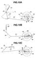
- FIGS. 10A to FIG. 10G are explanatory drawings successively illustrating the positional relation between the wiper blade and the movable contact of the position switch in a case of off-operation in the high-speed mode.
- FIGS. 1 to 10 are drawings for explaining control and structure of the wiper control device according to an embodiment of this invention, and FIG. 1 is a circuit diagram of the wiper control device.
- the wiper control device 1 shown in FIG. 1 is mainly composed of a wiper switch 2 , a wiper motor 3 , a position switch 4 , a control unit 5 , a pulse generator 6 and a washer motor 7 , and the control unit 5 includes a power circuit 8 , a reset circuit 9 , a controller 10 , a motor driving circuit 11 , a regulating circuit 12 , a backup circuit 13 and an oscillating circuit 14 .
- the wiper switch 2 is designed so as to be possible to select the operation mode of the wiper apparatus among a stop mode (OFF), an intermittent mode (INT), a low-speed mode (LOW), a high-speed mode (HI) and a wash mode (WASH), H-terminal of the wiper switch 2 is connected to a high-speed command signal input port P 4 of the controller 10 through No. 7 terminal of the control unit 5 , and L-terminal, I-terminal and W-terminal of the wiper switch 2 are connected to a low-speed command signal input terminal P 3 of the controller 10 through the pulse generator 33 and No. 6 terminal of the control unit 5 .
- the wiper switch 2 is operated into the high-speed mode (HI), the No.
- control unit 5 7 terminal of the control unit 5 is grounded through the H-terminal and E-terminal of the wiper switch 2 and a low-level signal is fed into the high-speed command signal input port P 4 of the controller 10 as a high-speed command signal, whereby the selection of the high-speed mode is recognized by the controller 10 .
- the wiper switch 2 is operated into the low-speed mode (LOW)
- the No. 6 terminal of the control unit 5 is grounded through the pulse generator 6 (non-actuation)
- the L-terminal and the E-terminal of the wiper switch 2 and a low-level signal is fed into the low-speed command signal input port P 3 of the controller 10 as a low-speed command signal, whereby the selection of the low-speed mode is recognized by the controller 10 .
- the wiper switch 2 when the wiper switch 2 is operated into the intermittent mode (INT), the No. 6 terminal of the control unit 5 is grounded intermittently through the pulse generator 6 (actuation), the L-terminal and the E-terminal of the wiper switch 2 , whereby the wiper motor 2 is operated intermittently at a low speed. If the wiper switch 2 is operated into the wash mode (WASH), the W-terminal of the wiper switch 2 is grounded through the E-terminal, whereby the washer motor 7 starts the rotation and a cleansing liquid is sprayed against the windshield glass.
- WASH wash mode
- the wiper motor 3 is a geared electric motor rotatable in the forward and reverse directions and provided with a first terminal 3 c (command brush terminal), a second terminal 3 a (low brush terminal) and a third terminal 3 b (high brush terminal), the first terminal 3 c of the wiper motor 3 is connected to a moving contact L 3 m of a third relay L 3 in the motor driving circuit 11 (described later) through No. 3 terminal of the control unit 5 , the second terminal 3 a of the wiper motor 3 is connected to a normal-closed contact L 1 c of a first relay L 1 in the motor driving circuit 11 through No.
- the wiper motor 3 is so designed as to rotate in the forward direction at a low speed according to an electric current flowing to the first terminal 3 c from the second terminal 3 a and as to rotate in the reverse direction at a high speed according to an electric current flowing to the third terminal 3 b from the first terminal 3 c.
- the wiper motor 3 is mechanically connected to a wiper linkage for actuating a wiper blade 20 reciprocatively as shown in FIG. 2, and a motor arm 21 is fixed to an output shaft 3 s of the wiper motor 3 at the base end thereof.
- the motor arm 21 is disposed with an eccentric bush 22 rotatably around an eccentric shaft 22 a in a range of 180° at the opposite end (top end) thereof, and the motor arm 21 is connected to a link connecting rod 23 through the eccentric bush 22 .
- the opposite end of the link connecting rod 23 is connected to one end of a pivot arm 24 secured to a pivot shaft 25 at the opposite end, the pivot shaft 25 is fixed with the base end of a wiper arm 26 at the opposite end and the wiper arm 26 is fitted with a wiper blade 20 at the top end thereof.
- the wiper motor 3 when the wiper motor 3 is actuated, the rotation of the wiper motor 3 is transmitted to the link connecting rod 23 as reciprocating motion through the motor arm 21 , the reciprocating motion of the link connecting rod 23 is converted into oscillatory motion of the wiper arm 26 and the wiper blade 20 through the pivot arm 24 and the pivot shaft 25 , and the wiper blade 20 is actuated swingingly on the windshield to wipe a windshield glass 30 .
- the eccentric bush 22 is attached to the motor arm 21 as mentioned above, and designed so as to turn on the motor arm 21 as much as 180° according to the rotational direction of the motor arm 21 .
- the motor arm 21 of the wiper linkage is so structured that the substantial length “La” of the motor arm 21 may become longer at the time the motor arm 21 fixed to the output shaft 3 s of the wiper motor 3 is rotated in the direction of arrow A (clockwise direction) according to the low-speed forward rotation of the wiper motor 3 as shown in FIG.
- the structural wiping range “Sb” (static wiping range) of the wiper linkage at the time of high speed operation as shown in FIG. 2B becomes narrower as compared with the structural wiping range “Sa” at the time of low speed operation as shown in FIG. 2A, consequently it is possible to remove the difference between the actual wiping ranges (dynamic wiping ranges) enlarged by addition of inertial force of the wiper blade 20 to the structural wiping ranges “Sa” and “Sb” at the time of low speed and high speed operation.
- the position switch 4 is housed in the wiper motor 3 , and provided with a high-potential plate 4 b which is formed in an arch-like shape from electrically conductive material, connected to a power source B and disposed on one side of circumference of a circle (upper side in FIG. 13 ), a low-potential plate 4 e which is formed similarly in the arch-like shape from the electrically conductive material, grounded and disposed on the other side of the circumference of the circle (lower side in FIG.
- a push member 4 p attached to the output shaft 3 s of the wiper motor 3 so as to rotate together with the output shaft 3 s
- a clutch member 4 c disposed coaxially with the high and low-potential plates 4 b and 4 e so as to be rotatable together with the push member 4 p by being pushed against the push member 4 p and a movable contact 4 m attached to the clutch member 4 c so as to slidingly touch the high and low-potential plates 4 b and 4 e as shown in FIGS. 3A to 3 C.
- the movable contact 4 m of the position switch 4 is connected to a position signal monitoring port P 5 of the controller 10 and a normal-closed contact L 4 c of a fourth relay L 4 in the motor driving circuit 11 , respectively through No. 4 terminal of the control unit 5 . Accordingly, a high-level signal is supplied to the position signal monitoring port P 5 of the controller 10 at the time when he movable contact 4 m is on the high-potential plate 4 b, and a low-level signal is supplied to the port P 5 at the time when the movable contact 4 m is on the low-potential plate 4 e.
- the clutch member 4 c of the position switch 4 c is so structured as to rotate together with the push member 4 p by being pushed against the push member 4 p as mentioned above, therefore, when the rotational direction of the wiper motor 3 is changed, the movable contact 4 m is left behind in the present position at the time of starting the reversed rotation while the push member 4 p makes nearly one revolution in the opposite direction together with the output shaft 3 s.
- the power circuit 8 in the control unit 5 is a constant voltage circuit connected between No. 5 terminal connected to the power source B through an ignition switch 15 and a power port P 2 of the controller 10 , and has a function to supply constant voltage to the controller 10 according to on-operation of the ignition switch 15 .
- the reset circuit 9 is a delay circuit connected between the power circuit 8 and a reset port P 1 of the controller 10 and has a function to reset the controller 10 , which is a microcomputer into the initial state by grounding the reset port P 1 for predetermined time after the on-operation of the ignition switch 15 .
- the controller 10 is a microcomputer (microprocessor) as described above, and provided with a low-speed driving signal output port P 6 for generating a low-speed driving signal in response to the low-speed command signal supplied from the wiper switch 2 through the low-speed command signal input port P 3 and the position signal supplied from the position switch 4 through the position signal monitoring port P 5 , a high-speed driving signal output port P 8 for generating a high-speed driving signal in response to the high-speed command signal supplied from the wiper switch 2 through the high-speed command signal input port P 4 and the position signal supplied through the position signal monitoring port P 5 , and oscillation ports P 9 and P 10 to be connected with the oscillating circuit 41 in addition to the aforementioned respective ports such as the reset port P 1 , the power port P 2 , the low-speed command signal input port P 3 , the high-speed command signal input port P 4 and the position signal monitoring port P 5 .
- a low-speed driving signal output port P 6 for generating a low-speed driving signal in response to the
- the motor driving circuit 11 is mainly composed of four relays L 1 , L 2 , L 3 and L 4 , two transistors TR 1 and TR 2 , respective ends of relay coils L 1 s, L 2 s and L 3 s of the first to third relays L 1 , L 2 and L 3 are connected to the power source side, and the other ends of the respective relay coils L 1 s, L 2 s and L 3 s are connected to the collector of the first transistor TR 1 of which emitter is grounded and of which base is connected to the high-speed driving signal output port P 8 of the controller 10 .
- a moving contact L 1 m of the first relay L 1 is connected to the power source side together with a normal-opened contact L 3 o of the third relay L 3 , and the normal-closed contact L 1 c of the first relay L 1 is connected to the second terminal (low brush) 3 a of the wiper motor 3 through the No. 1 terminal of the control unit 5 as mentioned above. Furthermore, a moving contact L 2 m of the second relay L 2 is grounded, and the normal-opened contact L 2 o of the second relay L 2 is connected to the third terminal (high brush) 3 b of the wiper motor 3 through the No. 2 terminal.
- the moving contact L 3 m of the third relay L 3 is connected to the first terminal (common brush) 3 c of the wiper motor 3 through the No. 3 terminal, and a normal-closed contact L 3 c of the third relay L 3 is connected to a moving contact L 4 m of the fourth relay L 4 .
- a relay coil L 4 s of the fourth relay L 4 is similarly connected to the power source side and another end of the relay coil L 4 s is connected to the collector of the second transistor TR 2 of which emitter is grounded and of which base is connected to the low-speed driving signal output port P 6 of the controller 10 . Further, a normal-opened contact L 4 o of the fourth relay L 4 is grounded, the normal-closed contact L 4 c of the fourth relay L 4 is connected to the first terminal 3 c of the wiper motor 3 through the No. 3 terminal of the control unit 5 and the moving contact L 4 m is connected to the normal-closed contact L 3 c of the third relay L 3 as described above.
- the circuit 12 is composed of two resistors R 1 and R 2 , and a diode D 1 , has a function to regulate the source voltage through the resistors R 1 , R 2 and apply the regulated voltage to the connection wire between the position signal monitoring port P 5 of the controller 10 and the movable contact 4 m of the position switch 4 , and the node between the resistors R 1 and R 2 is connected to the collector of the first transistor TR 1 through the diode D 1 .
- the circuit 12 when the high-speed driving signal is not generated from the high-speed driving signal output port P 8 of the controller 10 , the first transistor TR 1 is in the off-state, so that a high-level signal regulated through the resistors R 1 , R 2 is supplied to the position signal monitoring port P 5 of the controller 10 even if the movable contact 4 m of the position switch 4 separates from the high-potential plate 4 b and is on the opening between the both plates 4 b and 4 e .
- the transistor TR 1 becomes to the on-state and the node between the resistors R 1 and R 2 is grounded through the diode D 1 and the transistor TR 1 , accordingly the position signal to be supplied into the position signal monitoring port P 5 changes into a low-level at the same time of separation of the movable contact 4 m of the position switch 4 from the high-potential plate 4 b.
- the position signal to be supplied into the position signal monitoring port P 5 of the controller 10 changes from the low-level to the high-level and the controller is possible to detect the signal change (L ⁇ H) in the position signal at the same time when the push member 4 p arrives at the point before the position P 1 corresponding to the lower turning position of the wiper blade 20 as much as “ ⁇ a” (18°) in this embodiment and the movable contact 4 m separates from the low-potential plate 4 e as shown in FIG.
- the controller 10 detects the signal change (H ⁇ L) in the position signal at the same time when the push member 4 p arrives in the point before the position P 2 corresponding to the upper turning position of the wiper blade 20 as much as “ ⁇ a” (18°) and the movable contact 4 m touch the low-potential plate 4 e as shown in FIG. 3 B.
- the position signal to be supplied into the position signal monitoring port P 5 changes from the high-level to the low-level and the controller 10 detects signal change (H ⁇ L) in the position signal at the same time when the push member 4 p arrives in the point before the position P 1 corresponding to the lower turning position of the wiper blade 20 as much as “ ⁇ b” (18°) and the movable contact 4 m separates from the high-potential plate 4 b . Therefore, it is possible to turn the wiper blade 20 at the lower turning position accurately and possible to change the high-speed mode into the low-speed mode by switching over the output signal from the high-speed driving signal into the low-speed driving signal at the time of detecting the signal change.
- the circuit 12 has a function to cause the signal change in the position signal supplied to the position signal monitoring port P 5 of the controller 10 at the time when the wiper blade 20 arrives in the predetermined position before the lower turning position in both cases of the low-speed mode and the high-speed mode regardless of the rotational direction of the wiper motor 3 .
- the shifting angles ⁇ a and ⁇ b are set equally at 18 degrees in this embodiment, it is also possible to set the angle ⁇ b larger than the angle ⁇ a considering the difference in the inertial force caused by the difference of the operation speed of the wiper blade 20 .
- the backup circuit 13 is mainly composed of two transistors TR 3 , TR 4 , two capacitors C 1 , C 2 and two diodes D 2 , D 3 .
- the base of the transistor TR 3 is connected to the watchdog signal output port P 7 of the controller 10 through the capacitor C 1 , the emitter is grounded and the collector of the transistor TR 3 is connected to the power source B and the base of the transistor TR 4 through resistors and the diode D 2 .
- the collector of the transistor TR 4 is connected to the other end of the relay coil L 4 s of the fourth relay L 4 in the motor driving circuit 11 , the emitter of the transistor TR 4 is connected to the No. 7 terminal of the control unit 5 through the diode D 3 and the No. 7 terminal is connected to the H-terminal of the wiper switch 2 as mentioned above.
- the capacitor C 1 is charged, the transistor TR 3 is switched on and the transistor TR 4 is in the off-state so long as the watchdog signal is normally generated from the watchdog signal output port P 7 of the controller 10 , however if the output of the watchdog signal is interrupted by some failure, the capacitor C 1 is discharged and the transistor TR 3 is switched off, so that high potential voltage is applied to the base of the transistor TR 4 according to charging of the capacitor C 2 .
- the relay coil L 4 s of the fourth relay L 4 is grounded through the transistor TR 4 , the diode D 3 and the H-terminal and the E-terminal of the wiper switch 2 , so that the fourth relay L 4 is switched on and the wiper motor 3 is supplied with an electric current in the direction for low-speed forward rotation as shown in FIG. 5B (described later), whereby the wiper blade 18 is operated in the low speed.
- the wiper apparatus of this embodiment it is possible to actuate the wiper blade 20 in the low-speed by operating the wiper switch 2 into the high-speed mode (HI) even if the microcomputer of the controller 10 breaks down at the worst.
- HI high-speed mode
- the oscillating circuit 14 is composed of a clock signal generator 14 a and two capacitors, connected to the oscillation ports P 9 and P 10 and give a clock signal for the control to the controller 10 .
- a timer starts at step 101 , and stand-by processing is executed for 1 ms at step 103 in order to maintain a program period in 1 ms at all times.
- the control proceeds to step 104 after waiting for 1 ms, the timer starts again after being cleared at the step 104 .
- the switch signal supplied from the wiper switch 2 and the position signal supplied from the position switch 4 are read at steps 105 and 106 and anti-chattering processing is carried out at step 107 .
- the control proceeds to the next step after reading the signals supplied from the wiper switch 2 and the position switch 4 and confirming these signals to be stable without changing at the step 107 .
- Step 108 and 109 it is decided at steps 108 and 109 whether the wiper switch 2 is operated or not, that is whether a signal is supplied to the command signal input port P 3 or P 4 of the controller 10 or not.
- decision is done whether a high-speed operation flag F H and a low-speed operation flag F L are set or not at steps 110 and 111 , respectively.
- the respective relays L 1 to L 4 become to off-states entirely as shown in FIG. 5A since any signal is not generated from the controller 10 , and the wiper motor 3 is held in a state of stopping.
- the control returns to the step 103 and the aforementioned processing is repeated until the wiper switch 2 is operated.
- the wiper switch 2 When the wiper switch 2 is operated into the low-speed mode (LOW) in the off-state of the wiper switch 2 at time t 0 shown in FIGS. 6A and 6B, the low-speed command signal input port P 3 of the controller 10 is grounded through the wiper switch 2 , accordingly the control proceeds to step 116 from the step 109 by deciding the low-speed switch to be switched on (YES) at the step 109 of the flow chart shown in FIG. 4 .
- the control proceeds to steps 118 and 119 from the step 117 as the high-speed operation flag F H is cleared (NO) at the step 112 , the low-speed driving signal is generated from the low-speed driving signal output port P 6 at the step 119 without outputting the signal from the high-speed driving signal output port P 8 of the controller 10 .
- the transistor TR 2 in the motor driving circuit 11 becomes to the on-state and the coil L 4 s of the relay L 4 is excited and this fourth relay L 4 is only changed on as shown in FIG. 5 B.
- a feeder circuit to the wiper motor 3 which connects the second terminal 3 a (low brush) of the wiper motor 3 with the power source B through the normal-closed contact L 1 c of the first relay L 1 and grounds the first terminal 3 c of the wiper motor 3 through the normal-closed contact L 3 c of the third relay L 3 and the normal-opened contact L 4 o of the fourth relay L 4 , whereby the wiper motor 3 starts the forward rotation in the low speed and the wiper blade 20 starts the wiping operation in the low speed.
- the control returns to the step 103 , the aforementioned processing is repeated until the wiper switch 2 is operated again, and the low-speed wiping operation of the wiper blade 20 is continued.
- the wiper switch 2 When the wiper switch 2 is switched off in the state where the wiper blade 20 is actuated in the low speed (low-speed mode), the low-speed command signal from the wiper switch 2 disappears (the low-speed command signal input port P 3 is not grounded), the low-speed switch is decided not to be switched on (NO) at the step 109 of the flow chart shown in FIG. 4 .
- the control proceeds to the step 111 after deciding the high-speed operation flag F H not to be set (NO) at the step 110 and decision is done at the step 111 as to the state of low-speed operation flag F L .
- the low-speed operation flag F L is set (YES) at the step 116 in this case, the control proceeds to step 120 from the step 111 and the input signal supplied to the position signal monitoring port P 5 of the controller 10 from the position switch 4 , that is the present position of the wiper blade 20 is referred at the step 120 .
- the wiper switch 2 is switched off at time t 1 shown in FIG. 6A, that is at the time when the movable contact 4 m is on the low-potential plate 4 e of the position switch 4 , in other words, at the time when the wiper blade 20 is moving toward the lower turning position (home position) from the upper turning position, the position signal inputted to the position signal monitoring port P 5 is decided to be on the low-level (YES) at the step 120 since the movable contact 4 m of the position switch 4 is grounded through the low-potential plate 4 e .
- the control proceeds to the steps 114 and 115 after clearing the low-speed operation flag F L at step 121 , and the low-speed driving signal from the low-speed driving signal output port P 6 is interrupted at the step 115 .
- the movable contact 4 m separates from the low-potential plate 4 e of the position switch 4 and the current supplying circuit is shut off, however the wiper motor 3 is further rotated by inertia, and then an armature short circuit is formed as shown in FIG. 5A at the same time when the wiper blade 20 arrives at the lower turning position and the movable contact 4 m comes in contact with the high-potential plate 4 b , thereby stopping the wiper motor 3 and further stopping the wiper blade 20 at the lower turning position (home position).
- the wiper switch 2 is switched off from the low-speed mode (LOW) at time t 3 shown in FIG. 6B, that is at the time when the movable contact 4 m is on the high-potential plate 4 b of the position switch 4 , in other words, at the time when the wiper blade 20 is moving toward the upper turning position from the lower turning position, the position signal inputted to the position signal monitoring port P 5 is decided not to be on the low-level (NO) at the step 120 because the movable contact 4 m is connected with the power source B through the high-potential plate 4 b of the position switch 4 and the position signal monitoring port P 5 becomes to the high-level. Therefore, the control proceeds to the steps 118 and 119 from the step 120 , and the output of the low-speed driving signal is maintained from the low-speed driving signal output port P 6 , the low-speed forward rotation of the wiper motor 3 is continued.
- LOW low-speed mode
- the control proceeds to the steps 114 and 115 through the step 121 and the low-speed driving signal from the low-speed driving signal output port P 6 is interrupted at the step 115 .
- the wiper motor 3 continues the forward rotation in the low speed through the current supplying circuit as mentioned above, and stops by formation of the armature short circuit when the movable contact 4 m comes in contact with the high-potential plate 4 b after interruption of the current supplying circuit by separation of the movable contact 4 m from the low-potential plate 4 e of the position switch 4 (time t 5 in FIG. 6 B), thereby stopping the wiper blade 20 at the lower turning position (home position).
- An explanation will be given about the positional relationship between the wiper blade 20 (wiper linkage) and the movable contact 4 m of the position switch 4 on basis of FIGS. 7A to 7 D.
- the wiper blade 20 arrives in the predetermined position slightly before the upper turning position T U at time t 4 , the movable contact 4 m comes in contact with the low-potential plate 4 e of the position switch 4 as shown in FIG. 7B, and the position signal changes into the low-level thereby interrupting the output of the low-speed driving signal.
- the wiper motor 3 continues to rotate in the forward direction at the low speed through the current supplying circuit formed as shown in FIG. 5C, and the wiper blade 20 begins to move toward the lower turning position T L after arrival at the upper turning position T U .
- the wiper switch 2 When the wiper switch 2 is switched from the low-speed mode (LO) to the high-speed mode (HI) in the state where the wiper blade 20 is actuated in the low speed, the high-speed command signal is supplied to the controller 10 at the same time of disappearance of the low-speed command signal. Namely, the high-speed command signal input port P 4 of the controller 10 is grounded through the wiper switch 2 , whereby the control proceeds to step 122 from the step 108 by deciding the high-speed switch to be switched on at the step 108 (YES) in the flow chart shown in FIG. 4, and decision is done as to whether the high-speed operation flag F H is set or not at the step 122 .
- the control proceeds to step 123 from the step 122 because the high-speed operation flag F H is not set yet in this time (NO) and decision is done as to the low-speed flag F L at the step 123 .
- the control proceeds to step 124 through the step 123 since the low-speed operation flag F L is set at the step 116 during the previous low-speed operation (YES), and decision is done at the step 124 as to whether or not there is a negative going edge (H ⁇ L) or a positive going edge (L ⁇ H) in the position signal to be supplied to the position signal monitoring port P 5 of the controller 10 , in other words whether the wiper blade 20 arrives in the predetermined position before the upper turning position or the upper turning position or not.
- the control proceeds to the steps 118 and 119 from the step 124 , and the output of the low-speed driving signal from the low-speed driving signal output port P 6 is maintained, whereby the wiper motor 3 continues to rotate in the forward direction at the low speed until the position signal supplied from the position switch 4 changes.
- the control proceeds to steps 125 and 126 from the step 124 (YES), the high-speed operation flag F H is set at the step 125 and the low-speed operation flag F L is cleared at the step 126 . Furthermore, the high-speed driving signal is generated from the high-speed driving signal output port P 8 at step 127 and the output signal from the low-speed driving signal output port P 6 is interrupted.
- the transistor TR 2 becomes to the off-state and the coil L 4 s of the fourth relay L 4 is unexcited (OFF), and the transistor TR 1 becomes to the on-state by the output signal from the high-speed driving signal output port P 8 , whereby the coils L 1 s, L 2 s and L 3 s of the relays L 1 , L 2 and L 3 are excited (ON), respectively.
- a feeder circuit for the wiper motor 3 is formed as shown in FIG.
- the low-speed driving signal is switched over to the high-speed driving signal at time t 2 when the movable contact 4 m comes in contact with the low-potential plate 4 e of the position switch 4 as shown in FIG.
- the wiper motor 3 further continues to rotate in the forward direction (direction of arrow A) by inertia, and starts the high-speed reverse rotation at the time when the wiper blade 20 arrives at the upper turning position T U and the push member 4 p of the position switch 4 reaches the point P 2 as shown in FIG. 8 C.
- the movable contact 4 m is left behind on the low-potential plate 4 e together with the clutch member 4 c according to the reverse rotation of the wiper motor 3 until the push member 4 p comes in contact with the clutch member 4 c on the opposite side after about one revolution of the push member 4 p as shown in FIG. 8 D.
- the eccentric bush 22 provided to the motor arm 21 turns on the motor arm 21 as much as 180° along with the reverse rotation (in the direction of arrow B) of the motor arm 21 secured to the output shaft 3 s of the wiper motor 3 , whereby the substantial length of the motor arm 21 becomes shorter into “Lb” from “La” as shown in FIGS. 2A and 2B. Accordingly, the actual wiping range in the high-speed mode becomes equal to that in the low-speed mode.
- the wiper switch 2 is switched over from the low-speed mode into the high-speed mode at time t 3 shown in FIG. 6D, that is at the time when the wiper blade 20 is moving toward the lower turning position T L from the upper turning position T U as shown in FIG. 9A
- the low-speed driving signal is switched over into the high-speed driving signal at time t 4 when the movable contact 4 m separates from the low-potential plate 4 e of the position switch 4 as shown in FIG. 9 B and the positive going edge (L ⁇ H) is caused in the position signal to be inputted in the position signal monitoring port P 5 by the circuit 12 , that is at the time when the wiper blade 20 arrives in the position predetermined just before the lower turning position T L .
- the wiper motor 3 continues to rotate similarly in the forward direction (direction of arrow A) by inertia, and starts the high-speed reverse rotation at the time when the wiper blade 20 arrives at the lower turning position T L and the push member 4 p of the position switch 4 reaches the point P 1 as shown in FIG. 9 C.
- the movable contact 4 m is left behind on the high-potential plate 4 b during nearly one revolution of the push member 4 p .
- the eccentric bush 22 turns as much as 180° according to the reverse rotation of the wiper motor 3 and the substantial length of the motor arm 21 becomes shorter into “Lb” from “La” as mentioned above.
- the wiper motor 3 is so controlled as to be switched over from the low-speed forward direction into the high-speed reverse rotation at the time when the wiper blade 20 is in the lower turning position T L or the upper turning position T U , accordingly it becomes possible to prevent the wiper blade 20 to return in the middle of the wiping range on the windshield glass at the time of switching operation of the wiper mode and actuate the wiper blade 20 very properly. Furthermore, the change of the wiper mode into the high-speed mode from the low-speed mode is carried out speedily because the wiper motor 3 is switched over into the high-speed reverse rotation at the same time when the wiper blade 20 first arrives in the turning position after switching over the wiper switch 2 from the low-speed mode into the high-speed mode.
- the wiper switch 2 When the wiper switch 2 is operated into the high-speed mode (HI) in the off-state of the wiper switch 2 at time t 0 shown in FIG. 6E, the high-speed command signal input port P 4 is grounded through the wiper switch 2 , whereby it is decided that the high-speed switch is switched on (YES) at the step 108 of the flow chart shown in FIG. 4, the control proceeds to the step 122 from the step 108 and decision is done as to the high-speed operation flag F H at the step 122 .
- HI high-speed mode
- the control proceeds to the step 122 from the step 108 and decision is done as to the high-speed operation flag F H at the step 122 .
- the control proceeds to the step 123 from the stepl 22 , and decision is done as to whether the low-speed operation flag F L is set or not at the step 123 . Because the low-speed operation flag F L is also cleared (NO) at the step 113 , the control proceeds to step 129 and further proceeds to the steps 118 and 119 after setting the low-seed operation flag F L at the step 129 , and the low-speed driving signal is only output from the low-speed driving signal output port P 6 at the step 119 . Then, the control returns to the step 103 .
- the transistor TR 2 becomes to the on-state and the fourth relay L 4 is only changed on in the motor driving circuit 11 , whereby the feeder circuit is formed to the wiper motor 3 in the low-speed forward-rotational direction as shown in FIG. 5B, the wiper motor 3 starts the forward rotation in the low speed and the wiper blade 20 also starts the wiping operation in the low-speed.
- the control proceeds to the step 123 through the step 108 (YES) and the step 122 (NO) after returning to the step 103 , further proceeds to the step 124 from the step 123 because the low-speed operation flag F L is set (YES) at the step 129 and decision is done at the step 124 as to whether signal change is caused or not in the position signal from the position switch 4 . If the signal change is not caused (NO), the low-speed forward rotation of the wiper motor 3 is maintained at the steps 118 and 119 , and the aforementioned processing is repeated until the signal change appears in the position signal to be supplied to the position signal monitoring port P 5 from the position switch 4 .
- the control proceeds to the steps 125 and 126 from the step 124 (YES), and further proceeds to the steps 127 and 128 after setting the high-speed operation flag F H at the step 125 and clearing the low-speed operation flag F L at the step 126 .
- the high-speed driving signal is generated from the high-speed driving signal output port P 8 at the step 127 and the low-speed driving signal from the low-speed driving signal output port P 6 is interrupted at the step 128 .
- the transistors TR 2 and TR 1 become to the off-state and on-state respectively, whereby the fourth relay L 4 is turned off, the first to the third relays L 1 , L 2 and L 3 are turned on. Accordingly, the feeder circuit is formed to the wiper motor 3 in the high-speed reverse-rotational direction as shown in FIG. 5D, the low-speed forward rotation of the wiper motor 3 is switched over to the high-speed reverse rotation, and the wiper blade 20 starts the wiping operation at the high speed.
- the relationship between the positions of the wiper blade 20 and the movable contact 4 m of the position switch 4 is the same as shown in FIGS. 8A to 8 D. Furthermore, the substantial length of the motor arm 21 becomes shorter into “Lb” from “La” according to the turn of the eccentric bush 22 along with the change of the rotational direction of the wiper motor 3 similarly as described above (see FIGS. 2 A and 2 B).
- step 109 the control proceeds to step 130 through the step 110 and decision is done as to whether the negative going edge (H ⁇ L) appears or not in the position signal to be supplied to the position signal monitoring port P 5 at the step 130 because the high-speed operation flag F H is decided to be set (YES) at the step 110 (flag F H is already set at the step 125 ). If there is not such the signal change in the position signal (NO), the control proceeds to the steps 127 and 128 from the step 130 and the high-speed reverse rotation of the wiper motor 3 is held until the negative going edge is caused in the position signal.
- the position signal monitoring port P 5 is grounded through the resistor R 2 , the diode D 1 in the circuit 12 and the transistor TR 1 , so that the decision is done that the negative going edge (H ⁇ L) is caused in the position signal (YES) at the step 130 , the control proceeds to the steps 114 and 115 after resetting the high-speed operation flag F H at step 131 and the output signal from the high-speed driving signal output port P 8 is interrupted at the step 114 .
- the transistor TR 1 becomes to the off-state according to the interruption of the high-speed driving signal from the high-speed driving signal output port P 8 , whereby the coils L 1 s, L 2 s and L 3 s of the relays L 1 , L 2 and L 3 are unexcited and the feeder circuit for the wiper motor 3 is shut off.
- the wiper motor 3 further continues to rotate by inertia and stops in the state where the wiper blade 20 arrives in the lower turning position T L and the movable contact 4 m is in contact with the low-potential plate 4 e of the position switch 4 as shown in FIG. 10 D.
- the current supplying circuit for the wiper motor 3 is formed while the movable contact 4 m is in contact with the low-potential plate 4 e as shown in FIG. 5C, therefore the wiper motor 3 begins to rotate in the forward direction at the low speed as shown in FIG. 10 E.
- the movable contact 4 m is left behind on the low-potential plate 4 e until the push member 4 p comes in contact with the clutch member 4 c from reverse side after about one revolution in the forward direction (direction of arrow A) and keeps on forming the current supplying circuit of the wiper motor 3 while the wiper blade 20 go and return one time.
- the eccentric bush 22 attached to the motor arm 21 turns by 180°, whereby the substantial length of the motor arm 21 is restored to “La” from “Lb” and the structural wiping range (static wiping range) returns to “Sa” as shown in FIG. 2 A.
- the position signal changes temporary in the high-level through the circuit 12 because the transistor TR 1 becomes to the off-state owing to the interruption of the high-speed driving signal after the negative going edge is caused in the position signal at time t 4 shown in FIG. 6F according as the movable contact 4 m separates from the high-potential plate 4 b (see FIG. 10 C), however the position signal immediately changes into the low-level by the contact of the movable contact 4 m with the low-potential plate 4 e , and there is not effect on the control.
- the wiper switch 2 When the wiper switch 2 is switched form the high-speed mode (HI) to the low-speed mode (LOW) at time t 1 shown in FIG. 6G in the state where the wiper blade 20 is actuated in the high speed, the low-speed command port P 3 of the controller 10 is grounded through the wiper switch 2 at the same time of disappearance of the high-speed command signal from the wiper switch 2 . Accordingly, decision is done that the high-speed switch is not switched on (NO) at the step 108 and the low-speed switch is switched on (YES) at the step 109 , and the control proceeds to the step 117 through the step 116 . At the step 117 , decision is done as to the high-speed operation flag F H after setting the low-speed operation flag F L at the step 116 .
- the control proceeds to the steps 127 and 128 , the high-speed driving signal is maintained from the high-speed driving signal output port P 8 and the wiper motor 3 continues to rotate in the reverse direction at the high speed. Namely, the high-speed operation is kept on until the wiper blade 20 arrives in the predetermined position just before the lower turning position T L and the negative going edge is caused in the position signal supplied from the position switch 4 even after the arrival at the upper turning position T U .
- the control proceeds to step 134 from the step 133 (YES) and further proceeds to the steps 114 and 115 after setting the delay lag F D at the step 134 .
- the high-speed driving signal from the high-speed driving signal output port P 8 is interrupted at the step 114 .
- the transistor TR 1 becomes to the off-state according to the disappearance of the high-speed driving signal from the high-speed driving signal output port P 8 , all of the relay are turned off, but the wiper motor 3 further rotates in the reverse direction by inertia.
- the control returns to the step 103 and proceeds to the step 132 through the steps 104 ⁇ 108 (NO), the step 109 (YES), the steps 116 and 117 (YES), and decision is done at the step 132 as to the delay flag F D . Since the delay flag F D is set at the step 134 , the control proceeds to step 135 through the step 132 (YES), and decision is done as to whether count value of a delay counter D comes up to predetermined time “T” or not at the step 135 .
- the time “T” is set sufficiently longer than time “To” required for the movable contact 4 m of the position switch 4 to pass through the opening existing between high-potential plate 4 b and low-potential plate 4 e.
- step 136 From the step 135 (NO), increment of the delay counter D is carried out at the step 136 and the high and low-speed driving signals are kept in the interrupted states at the steps 114 and 115 , thereby maintaining off-states of the respective relays until the count value of the delay counter D amounts to “T”.
- the wiper motor 3 When the movable contact 4 m comes in contact with the low-potential plate 4 e of the position switch 4 at time t 3 shown in FIG. 6G by the inertial rotation of the wiper motor 3 , the wiper motor 3 is supplied with an electric current in the low-speed forward-rotational direction through the current supplying circuit formed as shown in FIG. 5 C and starts the low-speed forward rotation through the current supplying circuit at the time when the wiper blade 20 arrives at the lower turning position after the further inertial rotation in the reverse direction.
- the control proceeds to steps 137 and 138 from the step 135 (YES) and further proceeds to the steps 118 and 119 after clearing the delay counter D and the high-speed operation flag F H at the steps 137 and 138 , respectively.
- the low-speed driving signal is generated from the low-speed driving signal output port P 6 of the controller 10 at the step 119 , thereby turning on the transistor TR 2 and the fourth relay L 4 . Accordingly, the feeder circuit for the wiper motor 3 in the low-speed forward-rotational direction is formed as shown in FIG. 5 B and the wiper blade 20 continues the wiping operation in the low speed.
- the high-speed reverse rotation of the wiper motor 3 is changed into the low-speed forward rotation through the current supplying circuit after cutting off the power supply to the wiper motor 3 in the high-speed reverse-rotational direction through the motor driving circuit 11 at the time when the wiper blade 20 arrives in the predetermined position just before the lower turning position after the switching operation of the wiper switch 2 , subsequently the wiper motor 3 is supplied with an electric current in the low-speed forward-rotational direction through the motor driving circuit 11 for the low speed operation.
- the wiper control device is provided with the wiper switch, the wiper motor, the position switch, the controller, the motor driving circuit, and further provided with the regulating circuit and the backup circuit according to demand, and the controller changes the rotational direction of the wiper motor at the time the wiper blade arrives in the lower-turning position or the upper turning position in response to the switching operation of the wiper mode, for example. Therefore, it is possible to prevent unnatural phenomenon in that the wiper blade goes back from the middle on the windshield glass according as the rotational direction of the wiper motor is changed, and possible to prevent inconvenience such that rain drops and dust remain on the windshield glass unwiped by the backward movement of the wiper blade.
Landscapes
- Engineering & Computer Science (AREA)
- Mechanical Engineering (AREA)
- Control Of Direct Current Motors (AREA)
- Control Of Electric Motors In General (AREA)
Abstract
Description
Claims (14)
Applications Claiming Priority (4)
| Application Number | Priority Date | Filing Date | Title |
|---|---|---|---|
| JP11-199257 | 1999-07-13 | ||
| JP19922999A JP3886299B2 (en) | 1999-07-13 | 1999-07-13 | Wiper control device |
| JP19925799A JP3865536B2 (en) | 1999-07-13 | 1999-07-13 | Wiper control device |
| JP11-199229 | 1999-07-13 |
Publications (1)
| Publication Number | Publication Date |
|---|---|
| US6335601B1 true US6335601B1 (en) | 2002-01-01 |
Family
ID=26511423
Family Applications (1)
| Application Number | Title | Priority Date | Filing Date |
|---|---|---|---|
| US09/615,698 Expired - Lifetime US6335601B1 (en) | 1999-07-13 | 2000-07-13 | Wiper control device |
Country Status (2)
| Country | Link |
|---|---|
| US (1) | US6335601B1 (en) |
| EP (1) | EP1069013A3 (en) |
Cited By (5)
| Publication number | Priority date | Publication date | Assignee | Title |
|---|---|---|---|---|
| US20060226802A1 (en) * | 2003-09-15 | 2006-10-12 | Leslie Marentette | Reversing motor windshield wiper system |
| US20120256506A1 (en) * | 2009-10-05 | 2012-10-11 | Robert Bosch Gmbh | Circuit arrangement for operating an electric motor |
| US10046740B2 (en) * | 2016-04-15 | 2018-08-14 | Hyundai Motor Company | Wiper control system and method |
| CN110234546A (en) * | 2017-02-02 | 2019-09-13 | 株式会社电装 | Windscreen wiper device |
| CN110901880A (en) * | 2019-12-04 | 2020-03-24 | 中国直升机设计研究所 | Control method and control system for windshield wipers and windshield washing device |
Families Citing this family (3)
| Publication number | Priority date | Publication date | Assignee | Title |
|---|---|---|---|---|
| JP6349120B2 (en) * | 2014-03-27 | 2018-06-27 | 株式会社ミツバ | Wiper system control method and wiper system control apparatus |
| CN109653339B (en) * | 2019-01-31 | 2024-02-13 | 合肥工业大学 | Automatic open-close type rainwater grate |
| CN114018558A (en) * | 2021-11-05 | 2022-02-08 | 湖南联诚轨道装备有限公司 | Durability test control device for rail transit vehicle window wiper |
Citations (4)
| Publication number | Priority date | Publication date | Assignee | Title |
|---|---|---|---|---|
| US3887855A (en) * | 1973-11-28 | 1975-06-03 | Cleveland Machine Controls | Motor speed modifier control |
| US4227138A (en) * | 1978-04-10 | 1980-10-07 | General Electric Company | Reversible variable frequency oscillator for smooth reversing of AC motor drives |
| US4405887A (en) * | 1980-10-13 | 1983-09-20 | Nissan Motor Company, Limited | Drive circuit for a wiper device |
| US6249098B1 (en) * | 1999-03-05 | 2001-06-19 | Asmo Co., Ltd. | Wiper control apparatus and method capable of variably adjusting wiper blade motion |
Family Cites Families (5)
| Publication number | Priority date | Publication date | Assignee | Title |
|---|---|---|---|---|
| GB561210A (en) * | 1942-08-14 | 1944-05-10 | Henry Withers Kickweed Jenning | Improvements relating to windscreen wiper mechanism |
| US2959968A (en) * | 1957-04-18 | 1960-11-15 | Gen Motors Corp | Windshield wiper actuating mechanism |
| JPS57164843A (en) * | 1981-03-31 | 1982-10-09 | Nippon Denso Co Ltd | Driving device of window wiper |
| JPH1120619A (en) * | 1997-07-02 | 1999-01-26 | Mitsuba Corp | Wiper device |
| JP3886298B2 (en) * | 1999-07-12 | 2007-02-28 | 自動車電機工業株式会社 | Wiper motor |
-
2000
- 2000-07-10 EP EP00114115A patent/EP1069013A3/en not_active Withdrawn
- 2000-07-13 US US09/615,698 patent/US6335601B1/en not_active Expired - Lifetime
Patent Citations (4)
| Publication number | Priority date | Publication date | Assignee | Title |
|---|---|---|---|---|
| US3887855A (en) * | 1973-11-28 | 1975-06-03 | Cleveland Machine Controls | Motor speed modifier control |
| US4227138A (en) * | 1978-04-10 | 1980-10-07 | General Electric Company | Reversible variable frequency oscillator for smooth reversing of AC motor drives |
| US4405887A (en) * | 1980-10-13 | 1983-09-20 | Nissan Motor Company, Limited | Drive circuit for a wiper device |
| US6249098B1 (en) * | 1999-03-05 | 2001-06-19 | Asmo Co., Ltd. | Wiper control apparatus and method capable of variably adjusting wiper blade motion |
Cited By (9)
| Publication number | Priority date | Publication date | Assignee | Title |
|---|---|---|---|---|
| US20060226802A1 (en) * | 2003-09-15 | 2006-10-12 | Leslie Marentette | Reversing motor windshield wiper system |
| US7294986B2 (en) | 2003-09-15 | 2007-11-13 | Intier Automotive Closures Inc. | Reversing motor windshield wiper system |
| US20120256506A1 (en) * | 2009-10-05 | 2012-10-11 | Robert Bosch Gmbh | Circuit arrangement for operating an electric motor |
| US8749186B2 (en) * | 2009-10-05 | 2014-06-10 | Robert Bosch Gmbh | Circuit arrangement for operating an electric motor |
| US10046740B2 (en) * | 2016-04-15 | 2018-08-14 | Hyundai Motor Company | Wiper control system and method |
| CN110234546A (en) * | 2017-02-02 | 2019-09-13 | 株式会社电装 | Windscreen wiper device |
| US11014538B2 (en) * | 2017-02-02 | 2021-05-25 | Denso Corporation | Wiper device |
| CN110234546B (en) * | 2017-02-02 | 2022-12-20 | 株式会社电装 | Windscreen wiper device |
| CN110901880A (en) * | 2019-12-04 | 2020-03-24 | 中国直升机设计研究所 | Control method and control system for windshield wipers and windshield washing device |
Also Published As
| Publication number | Publication date |
|---|---|
| EP1069013A3 (en) | 2005-01-19 |
| EP1069013A2 (en) | 2001-01-17 |
Similar Documents
| Publication | Publication Date | Title |
|---|---|---|
| US3649898A (en) | Windshield wiper control apparatus | |
| US6335601B1 (en) | Wiper control device | |
| US5245259A (en) | Wiper apparatus for motor vehicle | |
| EP1069014B1 (en) | Wiper motor | |
| US6734644B2 (en) | Control method for wiper apparatus | |
| KR950002503B1 (en) | Wiper control system | |
| JPS6048370B2 (en) | wiper device | |
| JP3886299B2 (en) | Wiper control device | |
| JP3865536B2 (en) | Wiper control device | |
| US4731566A (en) | Intermittent drive controller for windshield wiper motor | |
| JP3865537B2 (en) | Wiper device | |
| JP3491518B2 (en) | Wiper operation control device | |
| JPS6345395Y2 (en) | ||
| JP3654805B2 (en) | Wiper drive system | |
| JPH0341964Y2 (en) | ||
| JPH0315411Y2 (en) | ||
| JPH0357563Y2 (en) | ||
| KR19980056072A (en) | Wiper motor speed control system | |
| JPH0210046Y2 (en) | ||
| JPH08310349A (en) | Wiper controller | |
| JPS63162353A (en) | Wiper device for vehicle | |
| JPH079948A (en) | Wiper control device | |
| JPH04365655A (en) | Wiper control equipment | |
| JPH0826074A (en) | Wiper controller | |
| KR20180051113A (en) | Apparatus for controlling wiper of a vehicle and method thereof |
Legal Events
| Date | Code | Title | Description |
|---|---|---|---|
| AS | Assignment |
Owner name: JIDOSHA DENKI KOGYO KABUSHIKI KAISHA, JAPAN Free format text: ASSIGNMENT OF ASSIGNORS INTEREST;ASSIGNORS:KATO, MASARU;MATSUMOTO, YASUKI;YAMAZAKI, YARUO;REEL/FRAME:010983/0507 Effective date: 20000512 |
|
| AS | Assignment |
Owner name: JIDOSHA DENKI KOGYO KABUSHIKI KAISHA, JAPAN Free format text: CORRECTIVE ASSIGNMENT TO CORRECT THE ASSIGNOR'S NAME, PREVIOUSLY RECORDED AT REEL 010983, FRAME 0507;ASSIGNORS:KATO, MASARA;MATSUMOTO, YASUKI;YAMAZAKI, HARUO;REEL/FRAME:012115/0844 Effective date: 20000512 |
|
| STCF | Information on status: patent grant |
Free format text: PATENTED CASE |
|
| FEPP | Fee payment procedure |
Free format text: PAYOR NUMBER ASSIGNED (ORIGINAL EVENT CODE: ASPN); ENTITY STATUS OF PATENT OWNER: LARGE ENTITY |
|
| FPAY | Fee payment |
Year of fee payment: 4 |
|
| AS | Assignment |
Owner name: MITSUBA CORPORATION, JAPAN Free format text: MERGER;ASSIGNOR:JIDOSHA DENKI KOGYO;REEL/FRAME:020497/0590 Effective date: 20070304 |
|
| FPAY | Fee payment |
Year of fee payment: 8 |
|
| FPAY | Fee payment |
Year of fee payment: 12 |