US6331094B1 - Wheel chock for use in transporting a cycle on a vehicle - Google Patents
Wheel chock for use in transporting a cycle on a vehicle Download PDFInfo
- Publication number
- US6331094B1 US6331094B1 US09/690,148 US69014800A US6331094B1 US 6331094 B1 US6331094 B1 US 6331094B1 US 69014800 A US69014800 A US 69014800A US 6331094 B1 US6331094 B1 US 6331094B1
- Authority
- US
- United States
- Prior art keywords
- pair
- arms
- studs
- plate
- plunger
- Prior art date
- Legal status (The legal status is an assumption and is not a legal conclusion. Google has not performed a legal analysis and makes no representation as to the accuracy of the status listed.)
- Expired - Lifetime
Links
Images


Classifications
-
- B—PERFORMING OPERATIONS; TRANSPORTING
- B60—VEHICLES IN GENERAL
- B60P—VEHICLES ADAPTED FOR LOAD TRANSPORTATION OR TO TRANSPORT, TO CARRY, OR TO COMPRISE SPECIAL LOADS OR OBJECTS
- B60P3/00—Vehicles adapted to transport, to carry or to comprise special loads or objects
- B60P3/06—Vehicles adapted to transport, to carry or to comprise special loads or objects for carrying vehicles
- B60P3/07—Vehicles adapted to transport, to carry or to comprise special loads or objects for carrying vehicles for carrying road vehicles
- B60P3/073—Vehicle retainers
- B60P3/075—Vehicle retainers for wheels, hubs, or axle shafts
- B60P3/077—Wheel cradles, chocks, or wells
Definitions
- This invention relates to a wheel chock for retaining a cycle for transportation on a vehicle and more particularly to such a device which is removably mounted on a track on the floor of the transporting vehicle.
- Chocks are commonly employed to support cycles such as motorcycles for transportation on a vehicle such an aircraft or A truck.
- a typical such device is described in U.S. Pat. No. 3,785,517 issued Jan. 15, 1974 to Brajkovich.
- Such prior art devices while effective in retaining the cycle in position during transportation tend to be overly expensive in their construction. Further, they cannot as readily be removed and reinstalled as to be desired. This factor is of particular importance in aircraft transportation where the goods being transported varies from day to day and the compartment must be modified as need be to handle each type of goods.
- the device of the present invention overcomes these shortcoming by providing a device of simple and economical construction which can rapidly and easily be installed and removed from a transportation compartment.
- the device of the present invention is formed from a bar which is bent into a formation which includes a pair of opposing bottom arms which form a base and a first pair of opposing side arms spaced above the bottom arms which run slightly upturned from the bottom arms. Extending upwardly from the first pair of side arms are a second pair of opposing side arms, the top ends of the second pair of side arms being joined together by a cross arm forming a top piece.
- a substantially flat base plate is fixedly attached to the bottom arms.
- the base plate has a pair of longitudinally spaced studs attached thereto, these studs fitting into a receptacles in a track installed on the floor of the transportation compartment.
- a spring loaded plunger is located between the two studs, this plunger being driven by the spring into a receptacle in the track. With the studs and the plunger installed in the track, the chock is held firmly to the vehicle floor. The chock can be released from the track merely by pulling upwardly on the plunger and sliding the chock longitudinally and lifting upwardly.
- FIG. 1 is a top front perspective view of a bicycle installed in a preferred embodiment of the device of the invention
- FIG. 2 is a top front perspective view of the preferred embodiment
- FIG. 3 is a top perspective view of a device for use in securing and releasing the plunger of the preferred embodiment
- FIG. 4 is a side elevational plan view of the device of FIG. 3;
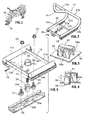
- FIG. 5 is an exploded perspective view of the base plate of the preferred embodiment illustrating its attachment to a floor track
- FIG. 6 is a front elevational view of the preferred embodiment shown installed in a floor track
- FIG. 7 is a side elevational view of the preferred embodiment installed in a floor track.
- FIG. 8 is a top plan view of the preferred embodiment installed in a floor track.
- the chock 10 is used to support the wheel of a motorcycle 15 on the floor of a transporting vehicle.
- the main portion of the chock 10 is fabricated of a single piece of bar metal which is formed in the indicated shape.
- a pair of opposing bottom arms 11 a and 11 b form a portion of the base for the device.
- a first pair of side arms 12 a and 12 b which are curved and run slightly upturned from the bottom arms.
- Extending upwardly from the first pair of side arms is a second pair of opposing side arms 13 a and 13 b which are substantially straight.
- Connecting the side arms together is a top arm 14 which has a “V” shape and forms a top piece.
- Base plate 16 Attached to the bottom arms 11 a and 11 b is base plate 16 .
- Foam rubber backings 18 are installed under each of arms 11 a and 11 b .
- Base plate 16 has a pair of in line studs 20 and 21 extending from its bottom wall and attached thereto by means of nuts 23 and 24 .
- plunger 26 Spaced about half way between the studs is plunger 26 which is urged downwardly by spring 27 .
- Cylindrical member 29 is fixedly attached to the wall of plate 16 .
- the top portion of plunger 26 fits through cylindrical member 29 , the plunger being retained to member 29 by means of pin 31 which fits through opposing apertures formed in member 29 and opposing elongated slots 26 a formed in the plunger.
- the spring is retained between pin. 31 and the base portion of plunger 26 thereby urging the base of the plunger into an opening 35 a in track 35 .
- Studs 20 and 21 fit into track 35 which is attached to the floor of the stowage compartment.
- This type of track is typically used in aircraft for attaching seats, cargo, etc. to the floor of the aircraft.
- the studs are installed in a pair of openings 35 a and then laterally slid under the narrower openings in the track(i.e. under the ledge portions 35 b ).
- the plunger which is positioned so that with the studs under the ledge portions fits into an opening 35 a is then released so it drops into the opening where it acts to retain the studs in position under the ledge portions.
- the chock is thus firmly retained in position.
- a pair of stiffening ribs 17 a and 17 b are formed by upwardly bending the opposite ends of plate 16 .
- This device is in the nature of a “butterfly” valve and includes a pair of oppositely positioned supports 40 a and 40 b on which an arm 41 is pivotally supported. Arm 41 thus can be manually actuated to drive the plunger 26 .
Landscapes
- Engineering & Computer Science (AREA)
- Health & Medical Sciences (AREA)
- Public Health (AREA)
- Transportation (AREA)
- Mechanical Engineering (AREA)
- Packaging Of Machine Parts And Wound Products (AREA)
Abstract
Description
Claims (8)
Priority Applications (1)
| Application Number | Priority Date | Filing Date | Title |
|---|---|---|---|
| US09/690,148 US6331094B1 (en) | 2000-10-17 | 2000-10-17 | Wheel chock for use in transporting a cycle on a vehicle |
Applications Claiming Priority (1)
| Application Number | Priority Date | Filing Date | Title |
|---|---|---|---|
| US09/690,148 US6331094B1 (en) | 2000-10-17 | 2000-10-17 | Wheel chock for use in transporting a cycle on a vehicle |
Publications (1)
| Publication Number | Publication Date |
|---|---|
| US6331094B1 true US6331094B1 (en) | 2001-12-18 |
Family
ID=24771287
Family Applications (1)
| Application Number | Title | Priority Date | Filing Date |
|---|---|---|---|
| US09/690,148 Expired - Lifetime US6331094B1 (en) | 2000-10-17 | 2000-10-17 | Wheel chock for use in transporting a cycle on a vehicle |
Country Status (1)
| Country | Link |
|---|---|
| US (1) | US6331094B1 (en) |
Cited By (31)
| Publication number | Priority date | Publication date | Assignee | Title |
|---|---|---|---|---|
| US20030049090A1 (en) * | 2001-09-10 | 2003-03-13 | Condon Duane R. | Motorcycle and all-terrain vehicle mounted tie down bracket |
| US20030103831A1 (en) * | 2001-12-05 | 2003-06-05 | Alderman Leslie K. | Quick disconnect motorcycle tie-down system |
| US20030190207A1 (en) * | 2002-04-08 | 2003-10-09 | Klaus Junge | Transport container for unit goods |
| US6655885B2 (en) * | 2001-05-10 | 2003-12-02 | Robert C. Trauthwein | Tie down bar for motorcycles |
| US6715972B2 (en) * | 2001-02-03 | 2004-04-06 | Rueben Dale Jackson, Sr. | Rigid tie-down device for securing a two-wheeled vehicle |
| US6848873B1 (en) | 2003-02-03 | 2005-02-01 | Vernon R Husk | Tie down bar |
| US20050047887A1 (en) * | 2003-08-25 | 2005-03-03 | Mark Kenny | Vehicle restraint system |
| US6863481B2 (en) | 2003-07-21 | 2005-03-08 | Pingel Enterprise, Inc. | Wheel chock mounting plate assembly |
| NL1024419C2 (en) * | 2003-10-01 | 2005-04-05 | Tolsma Tankbouw B V | System is for transport of wheeled vehicles, such as motorbicycles, scooters and cars and comprises loading space with loading floor of a transport medium, such as freight vehicle, railway train, and sea container |
| US20050095077A1 (en) * | 2003-10-30 | 2005-05-05 | Bright Verona L. | Removable insert for truck box with integrated motorcycle support and tie down |
| US20050238455A1 (en) * | 2004-04-23 | 2005-10-27 | Toteff Thomas S | Dual purpose track for holding wheel chocks and strap clips to tie down dirt bikes to trailers |
| US20060027425A1 (en) * | 2004-08-06 | 2006-02-09 | Coyer Sidney O | Atv quik lock |
| US20080034496A1 (en) * | 2006-08-11 | 2008-02-14 | Ferno-Washington, Inc. | Arresting device of a cot fastening system |
| US20080128220A1 (en) * | 2006-12-01 | 2008-06-05 | Hartmann George S | Portable Wheel Chock |
| US20080185489A1 (en) * | 2007-02-02 | 2008-08-07 | Glenn Alan Ehrgott | Systems and methods for mounting objects |
| US20090001031A1 (en) * | 2007-06-28 | 2009-01-01 | U-Haul International, Inc. | Motorcycle chock |
| US8459910B2 (en) | 2011-05-23 | 2013-06-11 | Stewart BRINEGAR | Adjustable wheel stop system for limiting movement of ATV in pickup box |
| USD761701S1 (en) | 2014-05-02 | 2016-07-19 | Tracy Hutch Jobe | Motorcycle rack |
| US9409508B2 (en) * | 2014-05-30 | 2016-08-09 | Adam J. Graham | Portable and adjustable motorcycle wheel chock |
| US9505333B2 (en) | 2014-05-15 | 2016-11-29 | Tracy Hutch Jobe | Motorcycle rack for a pickup truck |
| US9550443B2 (en) | 2014-10-07 | 2017-01-24 | Bike Box, LLC | Vehicle containment and transport systems and methods |
| USD825397S1 (en) * | 2016-11-29 | 2018-08-14 | Nippon Sharyo, Ltd. | Bicycle rack for vehicle |
| USD825398S1 (en) * | 2016-11-29 | 2018-08-14 | Nippon Sharyo, Ltd. | Bicycle rack for vehicle |
| USD825399S1 (en) * | 2016-11-29 | 2018-08-14 | Nippon Sharyo, Ltd. | Bicycle rack for vehicle |
| USD840912S1 (en) * | 2016-11-29 | 2019-02-19 | Nippon Sharyo, Ltd. | Bicycle rack for vehicle |
| USD840913S1 (en) * | 2016-11-29 | 2019-02-19 | Nippon Sharyo, Ltd. | Bicycle rack for vehicle |
| US10569689B2 (en) * | 2017-05-17 | 2020-02-25 | Corey Barnett Johnson | Reconfigurable chock assembly |
| US20200189674A1 (en) * | 2018-12-14 | 2020-06-18 | Richard Dove | Utility Trailer |
| US11021139B2 (en) | 2019-08-07 | 2021-06-01 | Motis Brands, Inc. | Adjustable wheel chock system |
| US11447200B2 (en) * | 2019-04-22 | 2022-09-20 | Michael W. Errickson, JR. | Motorcycle locking system |
| USD987541S1 (en) | 2019-08-07 | 2023-05-30 | Motis Brands, Inc. | Wheel chock |
Citations (10)
| Publication number | Priority date | Publication date | Assignee | Title |
|---|---|---|---|---|
| US1776935A (en) * | 1929-01-05 | 1930-09-30 | Evans Auto Loading Co Inc | Shipping device |
| US1780277A (en) * | 1929-01-05 | 1930-11-04 | Evans Auto Loading Co Inc | Shipping device |
| US2829738A (en) * | 1954-08-25 | 1958-04-08 | Joseph C Vasquez | Collapsible chock |
| US2858905A (en) * | 1956-06-29 | 1958-11-04 | Fahland Frank | Adjustable wheel block |
| US3779517A (en) | 1972-04-25 | 1973-12-18 | Nvf Co | Frame and jack assembly |
| US3785517A (en) | 1971-09-30 | 1974-01-15 | W Brajkovich | Motorcycle carrier and chock |
| US5037255A (en) * | 1990-02-26 | 1991-08-06 | Standard Car Truck Company | Wheel chock for a motor vehicle container |
| US5462398A (en) | 1994-01-11 | 1995-10-31 | Hymer; Robert F. | Motorcycle carrier |
| US5899655A (en) | 1997-06-27 | 1999-05-04 | Miller; Bob C. | Vehicle transporting device |
| US6065914A (en) * | 1996-06-13 | 2000-05-23 | Fotou; Dean H. | Apparatus for securing a vehicle |
-
2000
- 2000-10-17 US US09/690,148 patent/US6331094B1/en not_active Expired - Lifetime
Patent Citations (10)
| Publication number | Priority date | Publication date | Assignee | Title |
|---|---|---|---|---|
| US1776935A (en) * | 1929-01-05 | 1930-09-30 | Evans Auto Loading Co Inc | Shipping device |
| US1780277A (en) * | 1929-01-05 | 1930-11-04 | Evans Auto Loading Co Inc | Shipping device |
| US2829738A (en) * | 1954-08-25 | 1958-04-08 | Joseph C Vasquez | Collapsible chock |
| US2858905A (en) * | 1956-06-29 | 1958-11-04 | Fahland Frank | Adjustable wheel block |
| US3785517A (en) | 1971-09-30 | 1974-01-15 | W Brajkovich | Motorcycle carrier and chock |
| US3779517A (en) | 1972-04-25 | 1973-12-18 | Nvf Co | Frame and jack assembly |
| US5037255A (en) * | 1990-02-26 | 1991-08-06 | Standard Car Truck Company | Wheel chock for a motor vehicle container |
| US5462398A (en) | 1994-01-11 | 1995-10-31 | Hymer; Robert F. | Motorcycle carrier |
| US6065914A (en) * | 1996-06-13 | 2000-05-23 | Fotou; Dean H. | Apparatus for securing a vehicle |
| US5899655A (en) | 1997-06-27 | 1999-05-04 | Miller; Bob C. | Vehicle transporting device |
Cited By (38)
| Publication number | Priority date | Publication date | Assignee | Title |
|---|---|---|---|---|
| US6715972B2 (en) * | 2001-02-03 | 2004-04-06 | Rueben Dale Jackson, Sr. | Rigid tie-down device for securing a two-wheeled vehicle |
| US6655885B2 (en) * | 2001-05-10 | 2003-12-02 | Robert C. Trauthwein | Tie down bar for motorcycles |
| US20030049090A1 (en) * | 2001-09-10 | 2003-03-13 | Condon Duane R. | Motorcycle and all-terrain vehicle mounted tie down bracket |
| US6805522B2 (en) * | 2001-09-10 | 2004-10-19 | Ring Products | Motorcycle and all-terrain vehicle mounted tie down bracket |
| US20030103831A1 (en) * | 2001-12-05 | 2003-06-05 | Alderman Leslie K. | Quick disconnect motorcycle tie-down system |
| US6761519B2 (en) * | 2001-12-05 | 2004-07-13 | Leslie K. Alderman | Quick disconnect motorcycle tie-down system |
| US20030190207A1 (en) * | 2002-04-08 | 2003-10-09 | Klaus Junge | Transport container for unit goods |
| US6814529B2 (en) * | 2002-04-08 | 2004-11-09 | Friedola Gebr, Holzapef Gmbh & Co. Kg | Transport container for unit goods |
| US6848873B1 (en) | 2003-02-03 | 2005-02-01 | Vernon R Husk | Tie down bar |
| US6863481B2 (en) | 2003-07-21 | 2005-03-08 | Pingel Enterprise, Inc. | Wheel chock mounting plate assembly |
| US20050047887A1 (en) * | 2003-08-25 | 2005-03-03 | Mark Kenny | Vehicle restraint system |
| WO2005021325A3 (en) * | 2003-08-25 | 2005-08-25 | Proequipment Llc | Vehicle restraint system |
| NL1024419C2 (en) * | 2003-10-01 | 2005-04-05 | Tolsma Tankbouw B V | System is for transport of wheeled vehicles, such as motorbicycles, scooters and cars and comprises loading space with loading floor of a transport medium, such as freight vehicle, railway train, and sea container |
| US20050095077A1 (en) * | 2003-10-30 | 2005-05-05 | Bright Verona L. | Removable insert for truck box with integrated motorcycle support and tie down |
| US6935670B2 (en) * | 2003-10-30 | 2005-08-30 | Verona Lynn Bright | Integrated truck box and removable insert |
| US20050238455A1 (en) * | 2004-04-23 | 2005-10-27 | Toteff Thomas S | Dual purpose track for holding wheel chocks and strap clips to tie down dirt bikes to trailers |
| US6966734B2 (en) * | 2004-04-23 | 2005-11-22 | Toteff Thomas S | Dual purpose track for holding wheel chocks and strap clips to tie down dirt bikes to trailers |
| US20060027425A1 (en) * | 2004-08-06 | 2006-02-09 | Coyer Sidney O | Atv quik lock |
| US20080034496A1 (en) * | 2006-08-11 | 2008-02-14 | Ferno-Washington, Inc. | Arresting device of a cot fastening system |
| US7549690B2 (en) * | 2006-08-11 | 2009-06-23 | Ferno-Washington, Inc. | Arresting device of a cot fastening system |
| US20080128220A1 (en) * | 2006-12-01 | 2008-06-05 | Hartmann George S | Portable Wheel Chock |
| US20080185489A1 (en) * | 2007-02-02 | 2008-08-07 | Glenn Alan Ehrgott | Systems and methods for mounting objects |
| US20090001031A1 (en) * | 2007-06-28 | 2009-01-01 | U-Haul International, Inc. | Motorcycle chock |
| US8459910B2 (en) | 2011-05-23 | 2013-06-11 | Stewart BRINEGAR | Adjustable wheel stop system for limiting movement of ATV in pickup box |
| USD761701S1 (en) | 2014-05-02 | 2016-07-19 | Tracy Hutch Jobe | Motorcycle rack |
| US9505333B2 (en) | 2014-05-15 | 2016-11-29 | Tracy Hutch Jobe | Motorcycle rack for a pickup truck |
| US9409508B2 (en) * | 2014-05-30 | 2016-08-09 | Adam J. Graham | Portable and adjustable motorcycle wheel chock |
| US9550443B2 (en) | 2014-10-07 | 2017-01-24 | Bike Box, LLC | Vehicle containment and transport systems and methods |
| USD825397S1 (en) * | 2016-11-29 | 2018-08-14 | Nippon Sharyo, Ltd. | Bicycle rack for vehicle |
| USD825398S1 (en) * | 2016-11-29 | 2018-08-14 | Nippon Sharyo, Ltd. | Bicycle rack for vehicle |
| USD825399S1 (en) * | 2016-11-29 | 2018-08-14 | Nippon Sharyo, Ltd. | Bicycle rack for vehicle |
| USD840912S1 (en) * | 2016-11-29 | 2019-02-19 | Nippon Sharyo, Ltd. | Bicycle rack for vehicle |
| USD840913S1 (en) * | 2016-11-29 | 2019-02-19 | Nippon Sharyo, Ltd. | Bicycle rack for vehicle |
| US10569689B2 (en) * | 2017-05-17 | 2020-02-25 | Corey Barnett Johnson | Reconfigurable chock assembly |
| US20200189674A1 (en) * | 2018-12-14 | 2020-06-18 | Richard Dove | Utility Trailer |
| US11447200B2 (en) * | 2019-04-22 | 2022-09-20 | Michael W. Errickson, JR. | Motorcycle locking system |
| US11021139B2 (en) | 2019-08-07 | 2021-06-01 | Motis Brands, Inc. | Adjustable wheel chock system |
| USD987541S1 (en) | 2019-08-07 | 2023-05-30 | Motis Brands, Inc. | Wheel chock |
Similar Documents
| Publication | Publication Date | Title |
|---|---|---|
| US6331094B1 (en) | Wheel chock for use in transporting a cycle on a vehicle | |
| US6612615B1 (en) | Trailer hitch cart attachment mechanism | |
| US7967311B2 (en) | Multi position step | |
| US5462398A (en) | Motorcycle carrier | |
| US4084736A (en) | Vehicle mounted motorcycle rack | |
| US5823596A (en) | Truck tailgate fence mechanism | |
| US4275981A (en) | Vehicle mounted motorcycle carrier | |
| US6789988B1 (en) | Device for latching a cargo load to a track | |
| US3724694A (en) | Wheel-less trailer | |
| US5501428A (en) | Stabilizer jack | |
| US5433357A (en) | Load carrying vehicle accessory | |
| US5265992A (en) | Tie down fitting for retaining objects to the floor or side wall of a vehicle | |
| US2299025A (en) | Steering wheel tray | |
| US6592147B2 (en) | Fender having element conforming to mounting bracket | |
| EP0143678B1 (en) | Removable fixing device of a seat on a support such as a car floor or a car structure | |
| US7416167B1 (en) | Winch removably mounted on vehicle side rails | |
| US5749685A (en) | Adjustable securing apparatus | |
| US4063750A (en) | Combination towbar and parking stand | |
| US4969657A (en) | Piano truck | |
| US4262831A (en) | Traffic cone rack for mounting on a vehicle | |
| US2831622A (en) | Motor vehicle spare wheel locking assembly | |
| US6981826B2 (en) | Tie down apparatus and method of use | |
| US4405148A (en) | Insert for vehicle tow bar | |
| US5120017A (en) | Vehicle seat adapter | |
| US4029245A (en) | Automobile material carrier |
Legal Events
| Date | Code | Title | Description |
|---|---|---|---|
| AS | Assignment |
Owner name: ANCRA INTERNATIONAL, LLC, CALIFORNIA Free format text: ASSIGNMENT OF ASSIGNORS INTEREST;ASSIGNOR:BURROWS, WARD C.;REEL/FRAME:011239/0202 Effective date: 20001009 |
|
| STCF | Information on status: patent grant |
Free format text: PATENTED CASE |
|
| FPAY | Fee payment |
Year of fee payment: 4 |
|
| FEPP | Fee payment procedure |
Free format text: PAT HOLDER NO LONGER CLAIMS SMALL ENTITY STATUS, ENTITY STATUS SET TO UNDISCOUNTED (ORIGINAL EVENT CODE: STOL); ENTITY STATUS OF PATENT OWNER: LARGE ENTITY |
|
| REMI | Maintenance fee reminder mailed | ||
| FEPP | Fee payment procedure |
Free format text: ENTITY STATUS SET TO UNDISCOUNTED (ORIGINAL EVENT CODE: BIG.); ENTITY STATUS OF PATENT OWNER: LARGE ENTITY |
|
| FPAY | Fee payment |
Year of fee payment: 8 |
|
| SULP | Surcharge for late payment |
Year of fee payment: 7 |
|
| REMI | Maintenance fee reminder mailed | ||
| FPAY | Fee payment |
Year of fee payment: 12 |
|
| SULP | Surcharge for late payment |
Year of fee payment: 11 |