US6251658B1 - Inertial impact drill for cytological applications - Google Patents
Inertial impact drill for cytological applications Download PDFInfo
- Publication number
- US6251658B1 US6251658B1 US09/593,473 US59347300A US6251658B1 US 6251658 B1 US6251658 B1 US 6251658B1 US 59347300 A US59347300 A US 59347300A US 6251658 B1 US6251658 B1 US 6251658B1
- Authority
- US
- United States
- Prior art keywords
- actuators
- inertial
- impact drill
- inertial impact
- pulses
- Prior art date
- Legal status (The legal status is an assumption and is not a legal conclusion. Google has not performed a legal analysis and makes no representation as to the accuracy of the status listed.)
- Expired - Lifetime
Links
Images


Classifications
-
- G—PHYSICS
- G01—MEASURING; TESTING
- G01N—INVESTIGATING OR ANALYSING MATERIALS BY DETERMINING THEIR CHEMICAL OR PHYSICAL PROPERTIES
- G01N1/00—Sampling; Preparing specimens for investigation
- G01N1/28—Preparing specimens for investigation including physical details of (bio-)chemical methods covered elsewhere, e.g. G01N33/50, C12Q
- G01N1/286—Preparing specimens for investigation including physical details of (bio-)chemical methods covered elsewhere, e.g. G01N33/50, C12Q involving mechanical work, e.g. chopping, disintegrating, compacting, homogenising
-
- C—CHEMISTRY; METALLURGY
- C12—BIOCHEMISTRY; BEER; SPIRITS; WINE; VINEGAR; MICROBIOLOGY; ENZYMOLOGY; MUTATION OR GENETIC ENGINEERING
- C12M—APPARATUS FOR ENZYMOLOGY OR MICROBIOLOGY; APPARATUS FOR CULTURING MICROORGANISMS FOR PRODUCING BIOMASS, FOR GROWING CELLS OR FOR OBTAINING FERMENTATION OR METABOLIC PRODUCTS, i.e. BIOREACTORS OR FERMENTERS
- C12M35/00—Means for application of stress for stimulating the growth of microorganisms or the generation of fermentation or metabolic products; Means for electroporation or cell fusion
- C12M35/02—Electrical or electromagnetic means, e.g. for electroporation or for cell fusion
Definitions
- This invention relates to an inertial impact drill, and is especially suitable for use in cytological applications, as a clinical or scientific instrument for making microscopic holes in biological tissue.
- U.S. Pat. No. 3,835,338 of Sep. 10, 1974 discloses an electrically controlled ultra-micromanipulator that utilizes three sets of electrostrictive actuators orthogonally arranged to move and position a probe in small incremental steps.
- U.S. Pat. No. 5,225,750 of Jul. 6, 1993 discloses a device that uses a piezoelectric or an electrostrictive element to generate rotary motion to, in turn, drive a plunger in controlled very small steps.
- the plunger moves a liquid to be injected through a microsyringe.
- U.S. Pat. No. 5,229,679 of Jul. 20, 1993 describes a micromanipulator for biological applications that uses piezoelectric or electrostrictive actuators to drive an inertial mass to control, through impact, the incremental displacement of an aim in very small steps, facilitating the positioning in three axes of a miniature instrument attached to the arm.
- the arm with the miniature instrument e.g., a micropipette
- the incremental forward motion may cause damage to the cell.
- Prime Tech a Japanese company, sells the PMM micromanipulator device, which uses a piezoelectric element to produce fine linear incremental forward motion of a micropipette used for injection of materials into cells.
- Narishige another Japanese company, sells a micromanipulator in conjunction with a micropipette to inject matter into biological cells.
- the device generates vibration using ultrasonic vibration for the penetration of the cell wall as the micromanipulator moves the micropipette forward.
- Japanese patent, Publication Number 03166079 A (1991) discloses a means for eliminating vibration at the tip of a micro-instrument driven by a piezoelectric element and for micro-motion of this instrument in a straight line.
- Japanese patent, Publication Number 04207982 A (1992) describes a piezoelectrically actuated micro-motion device in which two orthogonally placed piezoelectric actuators are driven by sinusoidal voltages.
- Japanese patent, Publication Number 04041187 (1992) shows apparatus similar to that of U.S. Pat. No. 5,229,679, with a foot pedal controller.
- Burleigh Instruments, Inc. of Fishers, N.Y., USA, sells a piezoelectric linear stepper motor, the LSS-1000 Inchworm® System, for positioning over a distance of many millimeters microelectrodes and micropipettes for in-vitro and n-vivo electrophysiological procedures.
- the Inchworm U.S. Pat. Nos. 3,902,084 and 3,902,085 produces sub-micrometer size steps with high acceleration and high velocity that enables the tip for the microelectrode or micropipette to penetrate many millimeters of biological tissue. This device, however, may cause damage to cells, especially the ova, because it produces large indentations in cell walls.
- Burleigh Instruments, Inc. also sells a piezo-electric actuator (the LSS-2000 Cell Penetrator System) for rapidly advancing microelectrodes and micropipettes in rapid programmable steps of up to 200 micrometers.
- This product has been successfully used, for example, to penetrate frog muscle fibers (Charleton and Robitaille, J. of Neuroscience, January “92, pp 297-305). However, this product does not work for cells that have thick walls, such as the ova.
- An inertial impact drill facilitates the penetration of cell walls with a minimum damage by imparting inertial impact on the tip of an insertion element micropipette or a microelectrode without any net displacement of the tip.
- the smooth penetration is further facilitated by the mechanical oscillation of the tip of the micropipette or microelectrode at their resonant frequencies that are significantly higher than the repetition rate of the impact pulses. Any forward motion that might be required, as the cell wall is being gradually eroded to make an opening, is provided by a separate micromanipulator to which the drill is attached.
- actuators are energized by triangular electrical pulses that approximate impulses and thus are constituted of a fundamental frequency and a very large series of harmonics with frequencies greater than 1 KHz. Consequently, one of these harmonics will be close to the natural resonant frequency of the micropipettes or microelectrodes and thus will excite mechanical oscillation at the natural resonant frequency, which is higher than the repetition rate of the impulses.
- the drill provided by the inventor has opposing actuators attached to opposite ends of an inertial mass.
- the actuators are biased with a dc voltage such that they are maintained at about one half of their maximum strain.
- mechanical stability of the actuator-inertial mass assembly and also an increased stiffness of the assembly including the mass, actuators and insertion element.
- the actuators are electrically connected in series between the source of dc reference voltage and the ground, as a result each stack is biased at approximately one half of the total dc reference voltage.
- the triangular electrical pulses are applied at an electrical junction between the two actuators.
- the strain on one actuator stack is reduced, while the strain on the opposing actuator is increased causing a corresponding displacement of the inertial mass.
- the bodies of the actuators are mechanically preloaded to further facilitate the mechanical stability of the actuator-inertial mass assembly and an increased stiffness of the assembly.
- one object of this invention is to provide an improved inertial impact drill which is adapted for the penetration of the walls of biological cells while minimizing damage to the cells.
- Another object of this invention is to provide an improved inertial impact drill that incorporates two opposing actuators that move, when appropriate electrical signals are applied to them, an inertial mass situated between the actuators.
- a further object of this invention is to provide an improved inertial impact drill in which the actuators are made of piezoelectric material.
- Still further object of this invention is to provide an improved inertial impact drill in which the actuators are made of electrostrictive material.
- Yet another object of this invention is to provide an improved inertial impact drill in which dynamic forces of an inertial mass are transferred to the body of the drill generating an impact or a series of impacts in the direction of the major axis of the body, the impacts being transferred to a micropipette or a microelectrode affixed to the body, such that no net displacement in the micropipette or microelectrode results.
- An additional object of this invention is to provide an improved inertial drill driven by electrical signals having waveforms triangular in shape so as approximate impulse waveforms and therefore have a large number of harmonic frequencies greater than 1 KHz thus facilitating mechanical resonant oscillation of the tip of the micropipette or the microelectrode, at frequencies much higher then 1 KHz.
- An additional object of this invention is to provide an improved inertial impact drill that comprises a drill mechanism and a driver/amplifier electrically connected to the drill mechanism.
- a further object of this invention is to provide an improved inertial impact drill for making microscopic holes especially in cells or other biological tissues, which is affixed to a micromanipulator that provides for positioning, and displacement control of the drill.
- Still another object of this invention is to provide an improved inertial impact drill having electrostrictive or piezoelectric actuators electrically connected in series and which have one contact of one of the actuators connected to a dc reference voltage, one contact of the second actuator connected to a common electrical ground, and the second electrical contacts of both actuators connected at a common point or junction.
- Yet a further object of this invention is to provide an improved inertial impact drill in which two actuators, connected to an inertial mass, are driven by electrical pulses having triangular waveforms applied to a common point between the two actuators and drive the actuators, such that the actuators are driven simultaneously by the electrical pulses so as to achieve a brief net displacement of the inertial mass first in one direction then in the opposite direction.
- Another object of this invention is to provide an improved drill per the preceding object in which the pulses have maximum amplitude equal to the magnitude of a dc reference voltage.
- Still an additional object of this invention is to provide an improved inertial impact drill having electromechanical actuators connected to an inertial mass in which opposing forces are applied to the mass by electrically energizing the actuators at times occurring between pulses, driving the actuators to approximately one half of their maximum strain imparted to the actuators, to achieve a mechanical preload of the inertial mass in order to keep the actuators and bonds between the inertial mass and the actuators in constant compression to facilitate mechanical stability and increase stiffness of the actuator mass.
- Another object of this invention is to provide an improved inertial impact drill per the preceding object in which preload is applied to the bodies of the actuators in order to further facilitate mechanical stability and increase stiffness thereof.
- a further object of this invention is to provide an improved inertial impact drill having electromechanical actuators driven by pulses in which the total number in a series of inertial impacts is a function of the number of pulses applied to the actuators, the number of pulses being controlled by the drill operator.
- Yet another object of his invention is to provide an improved inertial impact drill having an electromechanical actuator driven by pulses from a driver/amplifier in which the repetition rate, amplitude, and duration of the pulses can be controlled by the operator via the driver/amplifier, thus allowing the operator to optimize the efficiency of the penetration while minimizing damage to the object being penetrated by the drill, especially when that object is a cell.
- a still further object of this invention is to provide an inertial impact drill per the preceding object in which the number of pulses in controllable by the operator using a foot pedal electrically connected to the driver/amplifier.
- an inertial impact drill in accordance with the inventor is adapted for use in conjunction with elements, such as micropipettes or microelectrodes in cytological applications to facilitate penetration of cell walls/membranes without causing permanent damage to the cells.
- the drill operates by producing impacts and also mechanical oscillation of the tips of the micropipettes or microelectrodes affixed to the body of the drill, but does not impart a net displacement at the tips. Displacement and positioning are provided separately by a micromanipulator to which the body of the drill is affixed.
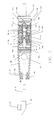
- FIG. 1 is a side view which illustrates, schematically, the internal mechanism of an inertial impact drill, in accordance with the invention, having two opposing actuators and an inertial mass.
- FIG. 2 is a perspective view which depicts the inertial impact shown in FIG. 1 mounted on the arm of a micromanipulator and holding the micropipette.
- FIG. 3 shows a typical electrical pulse that drives the inertial impact actuator stack.
- FIG. 4 schematically depicts six successive steps in the method of using the drill provided by the inventor in forming a hole in the wall of the biological cell held in place by holding pipette and being penetrated though its wall by an injection pipette.
- FIG. 5 is a schematic electrical diagram which illustrates the driver/amplifier which provides controlled electrical pulses for the drill.
- FIG. 6 is a block diagram of the controls for the drill.
- FIGS. 7 and 8 and 9 are a view similar to FIG. 1 and perspective views showing two other embodiments of the invention.
- FIG. 1 shows the cross-section of the mechanism of the inertial impact drill 20 (which also appears in FIG. 2 ).
- the small cylindrical inertial mass 1 is located between to actuators 5 A and 5 B.
- the actuators can be made of piezoelectric material or electrostrictive material. No change would be required in the mechanism to accommodate either type. Because a dc reference voltage is applied to the actuators 5 a and 5 b through pairs of electrical conductors 14 A and 14 B to generate on these actuators approximately 50% of the maximum strain, the actuators press firmly against the hemispherical bosses 6 A and 6 B enhancing mechanical stability of the assembly comprising the actuators and the small inertial mass as well as increasing the stiffness of the assembly. Hemispherical bosses provide a single point axial contact for the actuators.
- the inertial mass 1 is contained in the cylindrical outer center housing 3 and terminated on both ends by flexures 2 .
- Bosses 6 A and 6 B passing through apertures in the flexures support the inertial mass in the center of the outer center housing 3 .
- the actuators 5 A and 5 B, with respect to the inertial mass 1 the actuators are pressed against bosses 66 A and 66 B which are integral parts of the threaded end caps 8 A and 8 B.
- the assembly is also axially preloaded by the end caps that screw at 7 A and 7 B, into the outer end housing 4 .
- the outer center housing 3 , the outer end housing 4 and the end caps 8 A and 8 B comprise the body of the inertial impact drill.
- a holder block 9 is affixed to the body to support the an insertion element,micro-pipette 11 , clamped to the holder 9 by the clamp 10 .
- a microelectrode can be used instead of the micropipette 11 .
- the entire mechanism of the inertial impact drill is affixed to the mounting rod 13 .
- inertial impact drill 20 is mounted on micromanipulator 21 , and held in place by clamp 22 by the mounting rod 13 .
- Manual controls 23 , 24 , 25 , 26 , and 27 of the micromanipulator allow accurate pre-positioning of the tip of the micropipette or the microelectrode.
- the manipulator serves to advance or retract the inertial impact drill including the micropipette 11 or a microelectrode with respect to the body (which is a biological tissue or cell-as seen in FIG. 4 ).
- FIG. 3 shows the voltage pulses 33 that drive the actuators 5 A and 5 B.
- the amplitude A with respect to ground of the pulses is variable by the operator.
- C is the interval between the pulses equal to one over the pulse repetition rate, and B is the pulse width.
- the pulses are triangular in shape thus, in addition to the fundamental frequency determined by the pulse duration, the pulses are comprised of a large plurality of harmonics with frequencies greater than 1 KHz, which may be the repetition rate of the pulses.
- the result is a sharp displacement of the inertial mass 1 producing an impact on the body of the inertial drill 20 and therefore on the micropipette 11 or the microelectrode, but the impact also generates a mechanical oscillation of the tip of the micropipette or the microelectrode at their resonant frequency that is equal to or close to one harmonics. This may be of the order of 10 KHz 20 ⁇ KHz.
- the impact and the oscillation allow the tip of the micropipette or microelectrode, without net forward displacement, to penetrate a cell wall and, if appropriate, the nucleus membrane thereof with a minimum of damage to the cell.
- the tip of the micropipette or the microelectrode is brought by the micromanipulator 21 in intimate contact including slight pressure with the cell wall. No further forward motion is then needed for penetration.
- FIG. 4 illustrates the penetration process.
- the cell 41 in this example an ovum, is being held in place in the usual manner by the holding pipette 40 .
- Step 1 the 42 of the micropipette 11 is brought by the micromanipulator 20 (not shown) into close contact with the zona pellucida (the cell wall) of the ovum causing a slight indentation 43 . Due to impact transmitted to the tip of the micropipette from the body of the inertial impact drill and the mechanical oscillation of the tip and without any further net forward displacement of the tip 42 .
- Step 2 the zonapellucida is penetrated and a small cylindrical piece 44 is cut out of the zona pellucida.
- Step 3 shows how the tip 42 is withdrawn from the cell 41 and the cut out piece is discarded.
- the tip 42 is reinserted into the ovum and advanced forward until it touches the oolema (the membrane around the nucleus) producing a slight indentation. The tip then penetrates the oolema in the same manner as it has penetrated the zona pellucida as illustrated in Step 5 .
- Step 6 the tip is withdrawn after injecting a sperm, the oolema closes up, and the perforation in the zona pellucida soon also closes. The same procedure applies to other types of biological cells.
- FIG. 5 shows schematically the driver/amplifier circuit that drives the actuators 5 A and 5 B.
- An inverting broadband pulse amplifier 64 receives through its input terminal 67 pulses 33 .
- the pulses are amplified such that the sum of the voltage drops across the two actuators is equal to the dc reference voltage.
- the pulses are output on terminal 68 connected to the common junction 70 of one each of the pairs of the electrical conductors 14 A and 14 B.
- the second electrical conductor of the conductor pair 14 A is connected to the source of the dc reference voltage.
- the second electrical conductor of the conductor pair 14 B is connected to the ground.
- the dc reference voltage has a magnitude sufficient to generate 50% of the maximum strain on the actuators 5 A and 5 B when no pulses are applied to the common junction 70 .
- FIG. 6 shows diagrammatically the control unit and power supply 56 and the foot pedals assembly 59 connected to the control unit by cable 60 .
- a provision is made in the control unit 56 to separately control the repetition rate, pulse duration, and amplitude of two types of pulses, three controls for each type. Then the most appropriate pulse is selected using either foot pedal 57 or foot pedal 58 .
- the duration of a pulse train depends on how long does the operator depress a foot pedal. Cable 14 containing two pairs of electrical conductors 14 A and 14 B.
- FIG. 7 shows a hollow cone adapter, also called a “snout”, screwed onto the front of the housing 91 at its outer and 4 , facilitates mounting of either a hollow shaft pipette holder or a solid shaft pipette holder 84 .
- the pipette holder 4 is attached to the micromanipulator 21 along a side therof, by a clamp 86 , which compresses a spring plate 88 against the holder (FIG. 8 ). Only a part 87 of the micromanipulator to which the clamp 86 is attached by threaded knobs 89 is shown in FIG. 8 .
- a hole 92 in the side of the cone adapter optionally (see FIG. 9) allows fluid delivery tube 94 to be fed into the snout 80 and thus into and through the hollow shaft t 82 to the pipette 93 located at the end of the shaft.
- the insertion element (not shown in FIG. 7) is attached to the solid rod holder 84 by a clamp 97 attached to a block 90 in a manner similar to that shown in FIG. 2 .
- the hollow holder 82 is connected to the flexible fluid or suction tube 94 by a coaxial clamp 99 shown in FIG. 9 .
- the pipette 93 is connected to the hollow holder 82 by a coaxial clamp 101 .
- the cone adapter 80 holds the solid or hollow pipette holder 84 or 82 forward of the housing 91 , allowing for positioning of the pipette within the volume of a sample dish in a confined space. Additionally the cone adapter 80 acts to focus the pulse energy generated by the actuator, mass mechanism in housing 91 , thus transmitting a clean axial pulse without cross coupling of lateral vibration. This enhances the performance and flexibility in manipulation of the drill.
- the holders 82 or 84 are clamped at the exit 94 of the cone 80 by a collet mechanism 96 (a tapered shaft collet ring 95 ) in a reverse tapered opening 100 at the exit 94 of the cone 80 .
- the holders are mounted coaxially with the axis along which the inertial mass 102 (the axis of the drill and cylindrical housing 91 ) which provides for efficient transmission of the mechanical pulses via the holders ( 82 or 84 ) to the pipettes, as mentioned above.
- a seal 118 protects the interior of the drill mechanism from contaminants.
- the drill (FIGS. 7 - 9 )is of a design similar to shown in FIG. 1, but with the following difference.
- the DC reference voltage applied to the actuators 5 a and 5 b through pairs of electrical conductors 14 A and 14 B generates on these actuators approximately 50% of the maximum strain.
- the hardened steel hemispherical bosses 102 glued to the end of the actuators press firmly into the inner clamps 104 enhancing mechanical stability of the assembly comprising the actuators 5 A and 5 B and the small inertial mass 1 , as well as increasing the stiffness of the assembly.
- Hemispherical bosses 102 provide a single point axial contacts for the actuators 5 A and 5 B.
- the inertial mass 1 is contained in the single cylindrical outer housing 91 and terminated on both ends by flexures 2 .
- Inner clamps 104 passing through apertures in the flexures, support the inertial mass in the center of the outer housing 91 .
- the actuators are pressed into preload rings 108 and 110 captive within the cylindrical outer housing 91 .
- the preload ring 108 on the opposite end of the forward actuator 5 A axially preloads the assembly by screwing into the cylindrical outer housing.
- the preload ring 110 on the opposite end of the rear actuator 5 B axially preloads the assembly as the locking ring 112 is screwed into the cylindrical housing securing the assembly.
- the end cap 114 is screwed into the rear of the cylindrical outer housing 91 to seal the drill mechanism and protect it from contaminants. It also allows the electrical conductors 14 A and 14 B to exit through the rear of the cylindrical outer housing 91 so as not to interfere with positioning and operation.
- a tube holder 120 (see also FIG.9) is located at the rear of the housing 91 and held in place by a locking knob 122 .
- the tube holder secures the fluid tube connected to a micropipette via a hollow shaft pipette Holder (FIG. 9) or connected to a micropipette clamped to a holder 90 on a solid shaft pipette holder 84 (FIGS. 7 and 8 ).
- a micropipette a microelectrode can be used.
Abstract
Description
Claims (24)
Priority Applications (1)
| Application Number | Priority Date | Filing Date | Title |
|---|---|---|---|
| US09/593,473 US6251658B1 (en) | 1999-06-18 | 2000-06-14 | Inertial impact drill for cytological applications |
Applications Claiming Priority (2)
| Application Number | Priority Date | Filing Date | Title |
|---|---|---|---|
| US14001499P | 1999-06-18 | 1999-06-18 | |
| US09/593,473 US6251658B1 (en) | 1999-06-18 | 2000-06-14 | Inertial impact drill for cytological applications |
Publications (1)
| Publication Number | Publication Date |
|---|---|
| US6251658B1 true US6251658B1 (en) | 2001-06-26 |
Family
ID=22489331
Family Applications (1)
| Application Number | Title | Priority Date | Filing Date |
|---|---|---|---|
| US09/593,473 Expired - Lifetime US6251658B1 (en) | 1999-06-18 | 2000-06-14 | Inertial impact drill for cytological applications |
Country Status (3)
| Country | Link |
|---|---|
| US (1) | US6251658B1 (en) |
| AU (1) | AU5742500A (en) |
| WO (1) | WO2000078918A1 (en) |
Cited By (12)
| Publication number | Priority date | Publication date | Assignee | Title |
|---|---|---|---|---|
| US6475188B1 (en) * | 1999-05-20 | 2002-11-05 | Anthony David Baxter | Bilateral microinjector pump for freely moving animals in an operant chamber |
| US20030168940A1 (en) * | 2002-01-10 | 2003-09-11 | Kazuhito Kurita | Drive unit |
| US6661159B2 (en) * | 2001-07-18 | 2003-12-09 | Denso Corporation | Construction for transmitting displacement of piezoelectric element |
| US20040003679A1 (en) * | 2002-07-05 | 2004-01-08 | David Ide | Apparatus and method for in vitro recording and stimulation of cells |
| US20040247488A1 (en) * | 2003-06-04 | 2004-12-09 | Korea Institute Of Science And Technology | Smart pipette for cell manipulation and cell manipulation method for using the smart pipette |
| KR100475098B1 (en) * | 2002-11-12 | 2005-03-11 | 한국과학기술연구원 | Autonomous Bio-Manipulation Factory Apparatus For Manipulating Single Cell |
| US20050101019A1 (en) * | 2003-11-10 | 2005-05-12 | Mcclelland Paul H. | Method and device for targeted delivery of materials to selected single cells |
| US20080124787A1 (en) * | 2001-02-13 | 2008-05-29 | Avigenics, Inc. | Microinjection devices and methods of use |
| US20100230608A1 (en) * | 2006-03-02 | 2010-09-16 | Nanofactory Instruments Ab | Safe motion |
| EP2338972A1 (en) * | 2009-12-23 | 2011-06-29 | Eppendorf Ag | Apparatus and method for generating a tool motion |
| US8785177B2 (en) | 2011-11-04 | 2014-07-22 | The Board Of Trustees Of The University Of Illinois, A Body Corporate And Politic Of The State Of Illinois | Methods for nano-mechanoporation |
| WO2018210266A1 (en) * | 2017-05-18 | 2018-11-22 | Jiangsu Jitri Micro-Nano Automation Institute Co., Ltd | Flexure-guided piezo drill with large axial vibration and small lateral vibration |
Citations (8)
| Publication number | Priority date | Publication date | Assignee | Title |
|---|---|---|---|---|
| US3835338A (en) | 1973-08-23 | 1974-09-10 | A Martin | Electrically controlled ultra-micromanipulator |
| US4894579A (en) | 1987-05-29 | 1990-01-16 | Research Development Corporation Of Japan | Apparatus for effecting fine movement by impact force produced by piezoelectric or electrostrictive element |
| JPH03166079A (en) | 1989-11-24 | 1991-07-18 | Toshiro Higuchi | Micro-moving device for micromanipulator |
| JPH0441187A (en) | 1990-06-06 | 1992-02-12 | Prima Meat Packers Ltd | Foot switch type micromanipulator |
| JPH04207982A (en) | 1990-11-30 | 1992-07-29 | Prima Meat Packers Ltd | Micro motion device and moving method employing piezoelectric element producing impact force |
| US5225750A (en) | 1989-10-02 | 1993-07-06 | Prima Meat Packers, Ltd. | Microinjection apparatus, and method of controlling microinjection |
| US5229679A (en) | 1988-12-28 | 1993-07-20 | Prima Meat Packers, Ltd. | Microdrive apparatus |
| JPH0690770A (en) | 1991-03-29 | 1994-04-05 | Shimadzu Corp | Very small apparatus for micromanipulator |
-
2000
- 2000-06-14 US US09/593,473 patent/US6251658B1/en not_active Expired - Lifetime
- 2000-06-15 AU AU57425/00A patent/AU5742500A/en not_active Abandoned
- 2000-06-15 WO PCT/US2000/016574 patent/WO2000078918A1/en active Application Filing
Patent Citations (8)
| Publication number | Priority date | Publication date | Assignee | Title |
|---|---|---|---|---|
| US3835338A (en) | 1973-08-23 | 1974-09-10 | A Martin | Electrically controlled ultra-micromanipulator |
| US4894579A (en) | 1987-05-29 | 1990-01-16 | Research Development Corporation Of Japan | Apparatus for effecting fine movement by impact force produced by piezoelectric or electrostrictive element |
| US5229679A (en) | 1988-12-28 | 1993-07-20 | Prima Meat Packers, Ltd. | Microdrive apparatus |
| US5225750A (en) | 1989-10-02 | 1993-07-06 | Prima Meat Packers, Ltd. | Microinjection apparatus, and method of controlling microinjection |
| JPH03166079A (en) | 1989-11-24 | 1991-07-18 | Toshiro Higuchi | Micro-moving device for micromanipulator |
| JPH0441187A (en) | 1990-06-06 | 1992-02-12 | Prima Meat Packers Ltd | Foot switch type micromanipulator |
| JPH04207982A (en) | 1990-11-30 | 1992-07-29 | Prima Meat Packers Ltd | Micro motion device and moving method employing piezoelectric element producing impact force |
| JPH0690770A (en) | 1991-03-29 | 1994-04-05 | Shimadzu Corp | Very small apparatus for micromanipulator |
Non-Patent Citations (8)
| Title |
|---|
| High Speed Piezoelectric Positioning Systems (LSS-2000) Brochure, Burleigh Instruments, Inc., no date. |
| LSS-1000 Inchworm Microdrive System Brochure, Burleigh Instruments, Inc., no date. |
| MP-31 Piezoelectric Vibration Device Instruction Manual, Narishige Co., Ltd., no date. |
| PMM Piezo Micro Manipulator Brochure, Prime Tech, Ltd., no date. |
| PMM PRIMA Piezo Micro Manipulator Brochure, Prima Meat Packers, Ltd., no date. |
| Roland Hengstenberg, A Piezoelectric Device to Aid Penetration of Small Nerve Fibers with Microelectrodes, Journal of Neuroscience Methods, 4 (1981), pp. 249-255. |
| T. Higuchi, Innovative Actuators for Micromanipulation and Microinjection in Biotechnology, Automation in Biotechnology Proceedings of the 4th Toyota Conference, Oct. 21-24, 1990, 1991 Elsevier Science Publishers B.V. pp. 145-157. |
| W.J. Lederer, "Piezoelectric Translator. A Simple and Inexpensive Device to Move Microelectrodes and Micropipettes Small Distances Rapidly" (Pflugers Archives, vol. 399, No. 1, Sep. 1983, pp. 83-86). |
Cited By (26)
| Publication number | Priority date | Publication date | Assignee | Title |
|---|---|---|---|---|
| US6475188B1 (en) * | 1999-05-20 | 2002-11-05 | Anthony David Baxter | Bilateral microinjector pump for freely moving animals in an operant chamber |
| US20080124787A1 (en) * | 2001-02-13 | 2008-05-29 | Avigenics, Inc. | Microinjection devices and methods of use |
| US6661159B2 (en) * | 2001-07-18 | 2003-12-09 | Denso Corporation | Construction for transmitting displacement of piezoelectric element |
| US20030168940A1 (en) * | 2002-01-10 | 2003-09-11 | Kazuhito Kurita | Drive unit |
| US6809461B2 (en) * | 2002-01-10 | 2004-10-26 | Sony Corporation | Drive unit |
| US20040003679A1 (en) * | 2002-07-05 | 2004-01-08 | David Ide | Apparatus and method for in vitro recording and stimulation of cells |
| KR100475098B1 (en) * | 2002-11-12 | 2005-03-11 | 한국과학기술연구원 | Autonomous Bio-Manipulation Factory Apparatus For Manipulating Single Cell |
| US20040247488A1 (en) * | 2003-06-04 | 2004-12-09 | Korea Institute Of Science And Technology | Smart pipette for cell manipulation and cell manipulation method for using the smart pipette |
| US7501096B2 (en) * | 2003-06-04 | 2009-03-10 | Korean Institute Of Science And Technology | Smart pipette for cell manipulation and cell manipulation method for using the smart pipette |
| US20050101019A1 (en) * | 2003-11-10 | 2005-05-12 | Mcclelland Paul H. | Method and device for targeted delivery of materials to selected single cells |
| US7132242B2 (en) | 2003-11-10 | 2006-11-07 | Hewlett-Packard Development Company, L.P. | Method and device for targeted delivery of materials to selected single cells |
| US20100230608A1 (en) * | 2006-03-02 | 2010-09-16 | Nanofactory Instruments Ab | Safe motion |
| EP2338972A1 (en) * | 2009-12-23 | 2011-06-29 | Eppendorf Ag | Apparatus and method for generating a tool motion |
| CN102725391B (en) * | 2009-12-23 | 2014-07-23 | 埃佩多夫股份公司 | Apparatus and method for generating a tool motion |
| US20110212521A1 (en) * | 2009-12-23 | 2011-09-01 | Eppendorf Ag | Apparatus and Method for Generating a Tool Motion |
| CN102510899A (en) * | 2009-12-23 | 2012-06-20 | 埃佩多夫股份公司 | System and method for generating a tool motion |
| CN102725391A (en) * | 2009-12-23 | 2012-10-10 | 埃佩多夫股份公司 | Apparatus and method for generating a tool motion |
| US20130013115A1 (en) * | 2009-12-23 | 2013-01-10 | Eppendorf Ag | System and Method for Generating a Tool Motion |
| US10723991B2 (en) | 2009-12-23 | 2020-07-28 | Andreas Schirr | Apparatus and method for generating a tool motion |
| WO2011076389A1 (en) * | 2009-12-23 | 2011-06-30 | Eppendorf Ag | Apparatus and method for generating a tool motion |
| CN102510899B (en) * | 2009-12-23 | 2014-09-10 | 埃佩多夫股份公司 | System and method for generating a tool motion |
| US9422520B2 (en) * | 2009-12-23 | 2016-08-23 | Eppendorf Ag | System and method for generating a tool motion |
| US8785177B2 (en) | 2011-11-04 | 2014-07-22 | The Board Of Trustees Of The University Of Illinois, A Body Corporate And Politic Of The State Of Illinois | Methods for nano-mechanoporation |
| WO2018210266A1 (en) * | 2017-05-18 | 2018-11-22 | Jiangsu Jitri Micro-Nano Automation Institute Co., Ltd | Flexure-guided piezo drill with large axial vibration and small lateral vibration |
| CN110719952A (en) * | 2017-05-18 | 2020-01-21 | 江苏集萃微纳自动化系统与装备技术研究所有限公司 | Flexible guided piezoelectric drill with large axial vibration and small transverse vibration |
| CN110719952B (en) * | 2017-05-18 | 2022-04-05 | 苏州博致医疗科技有限公司 | Flexible guiding piezoelectric drill device with large axial vibration and small transverse vibration |
Also Published As
| Publication number | Publication date |
|---|---|
| AU5742500A (en) | 2001-01-09 |
| WO2000078918A1 (en) | 2000-12-28 |
Similar Documents
| Publication | Publication Date | Title |
|---|---|---|
| US6251658B1 (en) | Inertial impact drill for cytological applications | |
| US5225750A (en) | Microinjection apparatus, and method of controlling microinjection | |
| US10723991B2 (en) | Apparatus and method for generating a tool motion | |
| EP1594948B1 (en) | Method and devices for non-traumatic movement of a probe through biological cell material | |
| US6923790B2 (en) | Ultrasonically actuated needle pump system | |
| DE10029580C1 (en) | Device for removing body stones with an intracorporeal lithotripter | |
| Huang et al. | A universal piezo-driven ultrasonic cell microinjection system | |
| EP1187563A1 (en) | Medical instrument for treating biological tissue and method for transmitting pressure waves | |
| JP6139726B2 (en) | Actuator device with control device | |
| US20120238736A1 (en) | Device for shearing nucleic acids and particulates | |
| Huang et al. | Piezoelectric driven non-toxic injector for automated cell manipulation | |
| Hengstenberg | A piezoelectric device to aid penetration of small nerve fibers with microelectrodes | |
| JPH03166079A (en) | Micro-moving device for micromanipulator | |
| Kudoh et al. | Development of automatic micromanipulation system for biological cell sorter | |
| CN209812324U (en) | Piezoelectric ceramic actuating bionic device for detecting dynamic emission behavior of jellyfish stab-screw capsule | |
| CN110719952B (en) | Flexible guiding piezoelectric drill device with large axial vibration and small transverse vibration | |
| Lederer | Piezoelectric translator: a simple and inexpensive device to move microelectrodes and micropipettes small distances rapidly | |
| JP2004325836A (en) | Micromanipulator | |
| US20110224692A1 (en) | Device for applying high-frequency vibrations to hair for removing same | |
| Nobiling et al. | A piezotranslator with variable movement pattern: experiences with the penetration of very small cells | |
| Zhou et al. | A single cell penetration system by ultrasonic driving | |
| DE20023753U1 (en) | Medical instrument for treating biological tissue has pressure wave generator coupled to transmission device with liquid-filled pressure chamber provided with coupling membrane at its outlet | |
| Huixiang et al. | Ultrasonic Vibration Microdissection System for Molecular Analysis of Tissue | |
| JPH09262781A (en) | Microglipper device | |
| JPH0219765A (en) | Micromanipulator |
Legal Events
| Date | Code | Title | Description |
|---|---|---|---|
| AS | Assignment |
Owner name: BURLEIGH INSTRUMENTS, INC., NEW YORK Free format text: ASSIGNMENT OF ASSIGNORS INTEREST;ASSIGNORS:HENDERSON, DAVID A.;FASICK III, JOHN C.;CULHANE, ROBERT L.;AND OTHERS;REEL/FRAME:010910/0081 Effective date: 20000613 |
|
| STCF | Information on status: patent grant |
Free format text: PATENTED CASE |
|
| FEPP | Fee payment procedure |
Free format text: PAT HOLDER NO LONGER CLAIMS SMALL ENTITY STATUS, ENTITY STATUS SET TO UNDISCOUNTED (ORIGINAL EVENT CODE: STOL); ENTITY STATUS OF PATENT OWNER: LARGE ENTITY |
|
| REFU | Refund |
Free format text: REFUND - SURCHARGE, PETITION TO ACCEPT PYMT AFTER EXP, UNINTENTIONAL (ORIGINAL EVENT CODE: R2551); ENTITY STATUS OF PATENT OWNER: LARGE ENTITY |
|
| FPAY | Fee payment |
Year of fee payment: 4 |
|
| FPAY | Fee payment |
Year of fee payment: 8 |
|
| AS | Assignment |
Owner name: LUMEN DYNAMICS GROUP INC., CANADA Free format text: CHANGE OF NAME;ASSIGNOR:LUMEN DYNAMICS GROUP INC.;REEL/FRAME:025204/0952 Effective date: 20101001 |
|
| AS | Assignment |
Owner name: THORLABS, INC., NEW JERSEY Free format text: ASSIGNMENT OF ASSIGNORS INTEREST;ASSIGNOR:LUMEN DYNAMICS GROUP, INC.;REEL/FRAME:027120/0975 Effective date: 20111007 |
|
| FPAY | Fee payment |
Year of fee payment: 12 |