US6244733B1 - Low voltage track lighting system - Google Patents
Low voltage track lighting system Download PDFInfo
- Publication number
- US6244733B1 US6244733B1 US09/513,359 US51335900A US6244733B1 US 6244733 B1 US6244733 B1 US 6244733B1 US 51335900 A US51335900 A US 51335900A US 6244733 B1 US6244733 B1 US 6244733B1
- Authority
- US
- United States
- Prior art keywords
- lamp
- track
- contact
- housing
- outrigger
- Prior art date
- Legal status (The legal status is an assumption and is not a legal conclusion. Google has not performed a legal analysis and makes no representation as to the accuracy of the status listed.)
- Expired - Lifetime
Links
Images


Classifications
-
- H—ELECTRICITY
- H01—ELECTRIC ELEMENTS
- H01R—ELECTRICALLY-CONDUCTIVE CONNECTIONS; STRUCTURAL ASSOCIATIONS OF A PLURALITY OF MUTUALLY-INSULATED ELECTRICAL CONNECTING ELEMENTS; COUPLING DEVICES; CURRENT COLLECTORS
- H01R25/00—Coupling parts adapted for simultaneous co-operation with two or more identical counterparts, e.g. for distributing energy to two or more circuits
- H01R25/14—Rails or bus-bars constructed so that the counterparts can be connected thereto at any point along their length
- H01R25/147—Low voltage devices, i.e. safe to touch live conductors
-
- F—MECHANICAL ENGINEERING; LIGHTING; HEATING; WEAPONS; BLASTING
- F21—LIGHTING
- F21V—FUNCTIONAL FEATURES OR DETAILS OF LIGHTING DEVICES OR SYSTEMS THEREOF; STRUCTURAL COMBINATIONS OF LIGHTING DEVICES WITH OTHER ARTICLES, NOT OTHERWISE PROVIDED FOR
- F21V21/00—Supporting, suspending, or attaching arrangements for lighting devices; Hand grips
- F21V21/34—Supporting elements displaceable along a guiding element
- F21V21/35—Supporting elements displaceable along a guiding element with direct electrical contact between the supporting element and electric conductors running along the guiding element
-
- F—MECHANICAL ENGINEERING; LIGHTING; HEATING; WEAPONS; BLASTING
- F21—LIGHTING
- F21V—FUNCTIONAL FEATURES OR DETAILS OF LIGHTING DEVICES OR SYSTEMS THEREOF; STRUCTURAL COMBINATIONS OF LIGHTING DEVICES WITH OTHER ARTICLES, NOT OTHERWISE PROVIDED FOR
- F21V21/00—Supporting, suspending, or attaching arrangements for lighting devices; Hand grips
- F21V21/14—Adjustable mountings
- F21V21/30—Pivoted housings or frames
-
- F—MECHANICAL ENGINEERING; LIGHTING; HEATING; WEAPONS; BLASTING
- F21—LIGHTING
- F21W—INDEXING SCHEME ASSOCIATED WITH SUBCLASSES F21K, F21L, F21S and F21V, RELATING TO USES OR APPLICATIONS OF LIGHTING DEVICES OR SYSTEMS
- F21W2131/00—Use or application of lighting devices or systems not provided for in codes F21W2102/00-F21W2121/00
- F21W2131/40—Lighting for industrial, commercial, recreational or military use
-
- H—ELECTRICITY
- H01—ELECTRIC ELEMENTS
- H01R—ELECTRICALLY-CONDUCTIVE CONNECTIONS; STRUCTURAL ASSOCIATIONS OF A PLURALITY OF MUTUALLY-INSULATED ELECTRICAL CONNECTING ELEMENTS; COUPLING DEVICES; CURRENT COLLECTORS
- H01R2201/00—Connectors or connections adapted for particular applications
- H01R2201/08—Connectors or connections adapted for particular applications for halogen lamps
Definitions
- Track lighting is accepted both in commercial and residential applications.
- the advantages of track lighting are well recognized, in that, lights may be placed and the position of the lights may be changed to accommodate changes in display of merchandise in commercial applications and rearrangement of furniture in residential applications.
- track lighting has been generally arranged in straight lines.
- Track lighting often uses low voltage lamps, such as, 12-volt or 24-volt lamps. Customarily, the track carries a 110-volt current. When it is desirable to have a low voltage lamp, a lamp with a step down transformer is mounted on the track. The utilization of the step down transformer for each lamp makes the track lighting installation expensive. The track with many transformers is heavy in the event that there is a number of low voltage lamps on a given track.
- the present invention is a low voltage track lighting system.
- the system includes a bendable essentially flat track which may be formed to a desired configuration.
- the flat track includes a flat insulator base having a pair of opposed flat sides so that the base has a depth greater than its thickness.
- a thin flat electrical conductor is fixed to each of the flat sides so that there are electrical conductors on opposite sides of the track.
- a step down transformer adapted to be connected to a conventional source of electric power is connected to the track.
- a mount is connected to the track to support the track. The mount is adapted to be fixed to a supporting surface to be held thereby.
- An electric conductive path inside the mount is connected to each thin flat electrical conductor and to the step down transformer.
- An adapter is supported on the track and is in electric contact with each of the conductors of the track.
- a low voltage lamp is supported on the adapter and is in electric contact with the adapter to be energized by a current from the step down transformer.
- FIG. 1 is a perspective view of a low voltage track lighting system embodying the present invention
- FIG. 2 is an enlarged perspective view of a ceiling feed mount which is part of the subject system
- FIG. 3 is a cross sectional view through the mount of FIG. 2;
- FIG. 3A is a cross sectional view taken on line 3 A— 3 A of FIG. 3;
- FIG. 4 is an exploded view of the mount of FIGS. 2 and 3;
- FIG. 5 is a perspective view of an outrigger feed mount shown in FIG. 1;
- FIG. 6 is a cross sectional view taken through the outrigger mount of FIG. 5;
- FIG. 7 is an exploded view of the outrigger mount of FIGS. 5 and 6;
- FIG. 8 is a perspective view of an outrigger mount similar to the mount of FIG. 5;
- FIG. 9 is a cross sectional view of the mount of FIG. 8;
- FIG. 10 is an exploded view of the mount of FIGS. 8 and 9;
- FIG. 11 is a perspective view of a ceiling feed mount
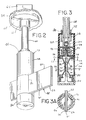
- FIG. 12 is a cross sectional view of the ceiling feed mount of FIG. 11;
- FIG. 13 is an exploded view of the ceiling feed mount of FIGS. 11 and 12;
- FIG. 14 is a ceiling feed mount similar to the mount shown in FIGS. 11 and 12, but with no step down transformer in the mount with a specially configured short section of track that accepts one low voltage lamp assembly;
- FIG. 15 is the mount of FIG. 14, but shown mounted in a wall rather than a ceiling into which any length of track can be inserted;
- FIG. 16 is a cross sectional view through the mount of FIG. 14;
- FIG. 17 is an exploded view of the mount of FIG. 14;
- FIG. 18 is an enlarged perspective view of a low voltage lamp assembly shown in FIG. 1;
- FIG. 19 is a cross sectional view taken on Line 19 — 19 of FIG. 18;
- FIG. 20 is an enlarged exploded view of an adapter of FIG. 19;
- FIG. 21 is an enlarged perspective view of a spherical lamp assembly shown in FIG. 1;
- FIG. 22 is a cross sectional view taken through the lampholder of FIG. 21;
- FIG. 23 is an exploded view of the parts of the spherical lampholder of FIG. 21;
- FIG. 24 is a perspective view of a link between abutting ends of two tracks
- FIG. 25 is an exploded view of the link of FIG. 24.
- FIG. 26 is a cross sectional view through the body of the link showing two tracks abutting and electrically connected.
- a low voltage track lighting system embodying the present invention is shown therein, and the system is generally indicated by numeral 30 .
- the track lighting system 30 is mounted in a structure having a conventional ceiling 32 , a first wall 34 , a second wall 36 , a third wall 38 , and a fourth wall 40 . Walls 36 and 38 are perpendicular to each other to define an outside corner.
- the track lighting system is supported in the structure on the ceiling and three of the walls.
- the track lighting system includes a first track 42 having an end mounted in a wall feed mount 44 secured to the wall 34 . Track 42 is also supported by a ceiling feed mount 46 which is secured to ceiling 32 .
- An outrigger feed mount 48 is secured to wall 36 and also supports track 42 .
- the track is bent around the outside corner formed by walls 36 and 38 and has one end mounted in a link 50 .
- a second track 52 has one end mounted in link 50 and the other mounted in a wall feed mount 54 , which is identical in construction to wall feed mount 44 .
- a ceiling feed mount 56 identical in construction to ceiling feed mount 46 , is fixed to ceiling 32 and supports track 52 .
- a lamp assembly 58 is mounted on track 42 and supported thereby.
- a second lamp assembly 60 is mounted on track 42 and is supported by the track.
- the tracks may be supported solely by the ceiling mounts or by the outrigger mounts or by the feed mounts 44 and 54 .
- the track may be bent, as is desired, to go around outside corners or into corners, or formed into any particular desired shape, whether it be a simple curve, or a serpentine configuration for a particular usage. While FIG. 1 shows typical installation configurations of the system, the flexible modular nature of the system allows many other configurations. For example, the outrigger mounting could be mounted to the ceiling or a floor.
- track 42 includes an insulating material base 61 , which may be formed by bending.
- the insulating material in the present instance, is a low-density polyethylene.
- Polyethylene base 61 has a thickness of 0.118 inches and a depth of 13 ⁇ 8 inch, so that the track may be bent with its depth perpendicular to the ceiling.
- Insulator plastic base or core 61 has two flat parallel sides. Identical aluminum conductors 62 and 63 , each having a thickness of 0.020 inches are secured to each side of the track so that the track has a conductor on opposite sides of the base.
- the plastic core 61 with the aluminum conductors 62 and 63 may be formed into a curve as needed. Although a specific size has been identified herein, it is readily apparent that the depth and thickness of the base or thickness and material of the conductor may be adjusted to accommodate a particular application.
- Step down transformer 64 is conventional in its construction and well known in the art, and is connected to a conventional source of 110-volt electric power (which is not shown herein).
- the step down transformer in this instance steps down the voltage to 12-volts, though other voltages may be used.
- Feed mount 46 includes a ceiling disk 65 which is fixed to ceiling 32 .
- the ceiling disk includes a nozzle 66 .
- a support conduit 68 is fixed in nozzle 66 at one end and the other end is fixed in an electric feed cylinder assembly 70 .
- Electric feed cylinder assembly includes a split housing 72 which is threadedly mounted in a connector cap 74 .
- Support conduit 68 is mounted in cap 74 and threadedly engages an internal lock 76 positioned inside cap 74 .
- a lock ring 78 is mounted on conduit 68 on the outside of cap 74 and held thereon by set screw 80 .
- Split housing 72 includes a slot 82 which extends through the housing and opens into the lower end of the housing, as viewed in FIG. 3.
- a lock cap 84 is threadedly mounted on the end of housing 72 to close the end of slot 82 .
- a pair of contact assemblies 86 and 88 is mounted in the housing. Each of the contact assemblies 86 and 88 has respective connector screws 90 and 92 .
- the connector screws 90 and 92 are connected to identical resilient contacts 94 and 96 , respectively.
- the contacts 94 and 96 have flat portions or pads 98 and 100 for engagement with the track.
- the contacts 94 and 96 are connected to step down transformer 64 through wires 102 and 104 , respectively, to provide an electric conductive path through feed mount 46 .
- the current from the step down transformer 64 is carried to the contact assemblies 86 and 88 , so that the contacts have a 12-volt potential, To though other voltages may be used.
- the contacts are offset relative to each other, as seen in FIG. 3A, so that the contacts do not contact each other when there is no track in the slot.
- Track 42 is positioned in slot 82 for mounting of the track in feed mount 46 .
- Contacts 94 and 96 have their respective flat portions 98 and 100 in contact with respective conductors of the track. The resilience of the contacts holds the flat portions in secure electrical connection with the respective conductors.
- outrigger feed mount 48 is best seen in FIGS. 5, 6 , and 7 .
- the outrigger mount has one end adapted to be secured to and supported by supporting surface wall 36 .
- Mount 48 includes an outrigger having a mounting disk 106 which has an outrigger tube 108 mounted thereon.
- a disk is held onto wall 36 by a canopy 110 , which has screws 112 secured in the wall.
- a cover plug 114 is mounted in the end of the tube opposite to the end secured to the wall.
- the cover plug includes an insulator post 116 .
- a tubular electric conductor sleeve 118 is mounted in plug 114 .
- the tubular sleeve is connected to an electric conductive path which has a wire terminal 120 connected to a wire 122 .
- An internal contact 124 is mounted on plug 114 and is connected to a wire 126 .
- the wires 122 and 126 are connected to a step down transformer, not shown herein, which is connected to a conventional source of 110-volt electric power, which is not shown.
- Track 42 has a mounting aperture 128 therein which receives insulator post 116 .
- a conductive screw 130 is mounted in post 116 in contact with tubular sleeve 118 .
- the track has its interior conductor 63 in electric contact with contact 124 , and exterior conductor 62 in contact with conductor screw 130 .
- the screw provides a dual function of holding the track onto the post and providing electrical connection with wire 122 through sleeve 118 .
- Wires 122 and 126 are connected to the step down transformer.
- a support outrigger mount 131 shown in FIGS. 8, 9 , and 10 may be used.
- Mount 131 is similar in construction to outrigger mount 48 where the same numbers are used to identify like parts.
- Mount 131 does not have an electric conductive path so that there are no wires.
- Mount 131 has the mounting disk 106 with the outrigger tube 108 mounted thereon.
- Disk 106 is secured to wall 36 by screws 132 mounted in toggle nuts 133 .
- Track 42 is secured to post 116 positioned in aperture 128 by screw 130 .
- FIGS. 11, 12 , and 13 show mount 134 secured to a ceiling, such as, ceiling 32 .
- the monopoint includes a canopy 135 with a step down transformer 136 mounted therein.
- the step down transformer 136 is connected to a conventional source of electric power (which is not shown).
- An electric conductive path is connected to the transformer.
- the path includes contact assemblies 137 and 138 connected to the transformer through wires 140 and 142 , respectively.
- Mount 134 includes a split housing 144 having a slot 146 formed therein.
- the contact assemblies 137 and 138 have resilient angle contacts 148 and 150 positioned in slot 146 of the housing.
- the contacts are offset from each other, as in the case of the ceiling feed mount, so that there is no electrical connection between the contacts when there is no track in the slot.
- a track 152 is mounted in the slot and is held in the slot by the frictional contact with the housing created by a pair of screws 154 . The screws are tightened to secure the track in place. Once the track is in place, the conductors of the opposite sides of the track are electrically connected to contacts 148 and 150 .
- a wall mount 155 is shown rotated 90°, so that it is mounted on wall 40 and wall 34 to support the ends of the tracks.
- the construction of wall mount 155 is similar to the construction of mount 134 , but the step down transformer is positioned externally of the mount.
- Like numbers are used for like parts of mounts 134 and 155 .
- Link 50 is shown in FIGS. 24, 25 , and 26 .
- Link 50 includes an insulator body having a male portion 160 and a female portion 162 .
- the male portion has a pair of bosses 164 which abut mounts 166 in female portion 162 .
- a pair of screws 168 are threadedly mounted in bosses 164 to hold the halves together. The screws are tightened to secure butt ends of tracks 52 and 42 together by frictional contact.
- the halves form a slot opening 170 at one end and a second slot opening 172 at the other end to receive butt ends of tracks 52 and 42 .
- a pair of electrical connector clips 174 and 176 are mounted within the housing. Clips 174 and 176 are mounted between bosses 164 and are in contact with respective sides of the tracks, so that there is an electrical connection between adjacent abutting conductors of the track.
- Lamp assembly 58 is best seen in FIGS. 18, 19 , and 20 .
- Lamp assembly 58 includes a fixture adapter 180 and a lamp holder 182 .
- the adapter includes a split adapter housing 184 having a track slot 186 formed therein. The halves of the housing 184 are held together by a conventional screw 188 .
- Slot 186 extends through the housing and opens at the upper end of the housing, as viewed in FIGS. 18 and 19.
- the housing has a threaded portion 190 which receives support cap 192 .
- the support cap closes the open end of slot 186 .
- a pair of resilient lamp contacts 194 and 196 is mounted in the housing. Each of the lamp contacts 194 and 196 has flat portions or elongated pads 198 and 200 , respectively.
- the housing includes a mounting groove 202 , which has a yoke 204 rotatably mounted therein.
- the yoke 204 is pivotally connected to lamp holder 182 .
- Lamp holder 182 has a conventional lamp socket 206 mounted therein.
- the lamp socket is connected to the contacts 194 and 196 through conventional wires 208 and 210 .
- the lamp holder includes a pivot bracket 212 held therein by screw 214 .
- the adapter is mounted on track 42 by placing track 42 into slot 186 , then screwing support cap 192 onto the threaded portion 190 to lock the track into the adapter.
- the flat portions 198 and 200 of the contacts 194 and 196 are in electrical connection with the respective conductors of the track.
- a low voltage lamp is mounted in socket 206 to be energized by the low voltage current flowing in the track.
- Lamp assembly 60 includes an adapter 220 , which is identical in construction to adapter 180 .
- a lamp holder 222 is mechanically and electrically connected to adapter 220 .
- the entire lamp holder 222 includes a fork 224 connected to the adapter through a connector assembly 226 .
- a shell 228 is pivotally mounted on fork 224 .
- the shell has a lamp socket 230 mounted therein. The socket is connected to the contacts in the adapter through conventional wires 232 and 234 .
- a tubular shield 236 is held in shell 228 by three resilient spring shield fingers 238 .
- Each of the resilient fingers has one end fixed to the shield and the other end includes a hook portion 240 , which engages shell 228 .
- Three resilient spring lamp fingers 242 are mounted on the inside of the shield.
- Each finger has a lamp hook 243 , which engages a conventional 12-volt lamp 246 to support the lamp.
- Each finger has a lens hook 244 which engages a conventional protective lens 245 to hold lens 245 a short distance from face of lamp 246 allowing air flow to cool the lamp.
- the lamp is surrounded by the shield so that heat generated by the lamp is largely absorbed by shield 236 .
- the spacing of the lamp from the shield and the spacing of the shield from the shell allows air to flow around the shield and the lamp to carry away heat to cool the lamp.
- tubular shield may be readily removed from shell 228 simply by releasing resilient fingers 238 . Upon removal of the shield, releasing clips 242 allows the lamp to be removed from the shield. The socket can now be removed for re-lamping.
- the lamps may be positioned anyplace along the tracks simply by removing the lock caps and disengaging the adapter body from the track. Inasmuch as the voltage operating through the track is only a low voltage of 12 volts, or other low voltage, it is possible for a person who does not have any training as an electrician to move the lamps or to add lamps without being in any danger. The low voltage is safe for even those who are not experienced in electrical matters.
- the various supporting devices may be used without the electrical contacts in the mount.
- the electrical feed cylinder assembly 70 may be utilized without the electrical contacts thereby providing only mechanical connection of the track to the ceiling.
- the outrigger may be utilized without the electrical contacts, as shown in FIGS. 8, 9 , and 10 , wherein outrigger mount is shown without the electrical contacts and all of the like parts of like numbers as for the outrigger 48 .
Abstract
Description
Claims (23)
Priority Applications (2)
| Application Number | Priority Date | Filing Date | Title |
|---|---|---|---|
| US09/513,359 US6244733B1 (en) | 2000-02-25 | 2000-02-25 | Low voltage track lighting system |
| CA002316551A CA2316551C (en) | 2000-02-25 | 2000-08-15 | Low voltage track lighting system |
Applications Claiming Priority (1)
| Application Number | Priority Date | Filing Date | Title |
|---|---|---|---|
| US09/513,359 US6244733B1 (en) | 2000-02-25 | 2000-02-25 | Low voltage track lighting system |
Publications (1)
| Publication Number | Publication Date |
|---|---|
| US6244733B1 true US6244733B1 (en) | 2001-06-12 |
Family
ID=24042928
Family Applications (1)
| Application Number | Title | Priority Date | Filing Date |
|---|---|---|---|
| US09/513,359 Expired - Lifetime US6244733B1 (en) | 2000-02-25 | 2000-02-25 | Low voltage track lighting system |
Country Status (2)
| Country | Link |
|---|---|
| US (1) | US6244733B1 (en) |
| CA (1) | CA2316551C (en) |
Cited By (46)
| Publication number | Priority date | Publication date | Assignee | Title |
|---|---|---|---|---|
| US6523970B1 (en) * | 2001-10-04 | 2003-02-25 | Scales, Iii Charles W. | Spotlight adaptor |
| US6582104B2 (en) * | 2001-08-02 | 2003-06-24 | Jack V. Miller | Decorative lighting fixtures |
| US20040005798A1 (en) * | 2002-07-05 | 2004-01-08 | Michael Lin | Track system of projector lamp and electrical connection device assembly thereof |
| US20040032742A1 (en) * | 2002-08-15 | 2004-02-19 | Dannatt Norbert H.W. | Luminaire with articulated and expandable joints |
| EP1421315A1 (en) * | 2001-07-31 | 2004-05-26 | Comfort Products, Inc. | Electrical track lighting system |
| US6755557B2 (en) * | 2000-08-23 | 2004-06-29 | Juno Manufacturing, Inc. | Lighting fixture |
| US20040160767A1 (en) * | 2003-02-14 | 2004-08-19 | Aaron Mobarak | Field bendable line voltage track lighting system |
| US20050207173A1 (en) * | 2004-03-18 | 2005-09-22 | Bazz Inc. | Track lighting system |
| US7105744B1 (en) | 2003-03-18 | 2006-09-12 | Regal King Comercial Offshore De Macau Limitada | Mounting bracket for electrical fixtures |
| US20070081347A1 (en) * | 2005-10-06 | 2007-04-12 | Catalina Lighting Inc. | Method and system for displaying lighting fixtures |
| US20070153509A1 (en) * | 2005-12-30 | 2007-07-05 | Cooper Technologies Company | Lighting system and method |
| US20070153516A1 (en) * | 2005-12-30 | 2007-07-05 | Cooper Technologies Company | Lighting system and method |
| US20070153551A1 (en) * | 2006-01-04 | 2007-07-05 | Hua-Rung Chiu | Conductive fixed structure of track light |
| US20070167043A1 (en) * | 2005-12-30 | 2007-07-19 | Cooper Technologies Company | Lighting system and method |
| US7322735B1 (en) | 2006-07-21 | 2008-01-29 | Minka Lighting, Inc. | Telescoping power medium |
| US20080080203A1 (en) * | 2006-09-29 | 2008-04-03 | Neufeglise Steven W | Rear deck warning light bar |
| US20080087464A1 (en) * | 2006-10-17 | 2008-04-17 | Patterson Brian T | Electrified ceiling framework |
| US7456357B1 (en) | 2002-03-27 | 2008-11-25 | Gardenia Industrial Limited | Mounting bracket for electrical fixtures |
| US20090109707A1 (en) * | 2007-10-30 | 2009-04-30 | Paul James Bartlett | Push button release for luminaires in a track lighting system |
| US20090239393A1 (en) * | 2008-03-20 | 2009-09-24 | Ashok Deepak Shah | Conductive Magnetic Coupling System |
| US20090284988A1 (en) * | 2008-05-14 | 2009-11-19 | Juno Manufacturing, Inc. | Led Track Lighting System |
| CN100582566C (en) * | 2008-05-30 | 2010-01-20 | 昆山百亨光电科技有限公司 | Illumination system |
| US20100055947A1 (en) * | 2008-08-28 | 2010-03-04 | Franklin Phoyeng Fong | Adapter For Line Voltage Track |
| US20100147127A1 (en) * | 2008-12-12 | 2010-06-17 | Credo Technology Corporation | Combination table-miter saw with adjustable light |
| CN102650858A (en) * | 2012-05-07 | 2012-08-29 | 天津金尤提乐成套电气工程有限公司 | Split plugging intelligent switch assembly and application method thereof |
| US8651711B2 (en) | 2009-02-02 | 2014-02-18 | Apex Technologies, Inc. | Modular lighting system and method employing loosely constrained magnetic structures |
| US8915609B1 (en) | 2008-03-20 | 2014-12-23 | Cooper Technologies Company | Systems, methods, and devices for providing a track light and portable light |
| US20150159840A1 (en) * | 2013-12-10 | 2015-06-11 | Diode-On Optoelectronics Limited | Modular track assembly for slidably mounting a track light |
| USD743621S1 (en) * | 2015-02-03 | 2015-11-17 | Colt International Clothing Inc. | Flexible and adaptable light harness and wiring |
| US9239134B1 (en) * | 2014-02-04 | 2016-01-19 | Colt International Clothing Inc. | Flexible and adaptable light harness and wiring |
| US9303854B2 (en) | 2013-03-12 | 2016-04-05 | Apex Technologies, Inc. | Electrical rail systems with axially interleaved contact arrays |
| USD779696S1 (en) * | 2002-01-07 | 2017-02-21 | The L.D. Kichler Co. | Lighting fixture |
| US9831642B2 (en) | 2016-04-25 | 2017-11-28 | Opto International, Inc. | Vertical support for shelving system and shelving system |
| US9857024B1 (en) * | 2012-04-01 | 2018-01-02 | Modular Services Company | Overhead support for medical equipment |
| US20180066817A1 (en) * | 2015-03-13 | 2018-03-08 | Shenzhen Jiawei Photovoltaic Lighting Co., Ltd. | Track head and track lamp |
| EP3321576A1 (en) * | 2016-11-09 | 2018-05-16 | Robert A. Sonneman | Ring power bar hanger for modular lighting system |
| US10018339B2 (en) | 2016-01-07 | 2018-07-10 | Robert A. Sonneman | Modular lighting system using hangers and power bars |
| US10041662B2 (en) | 2016-11-09 | 2018-08-07 | Robert A. Sonneman | Light bar for a lighting system |
| US10151466B2 (en) | 2016-11-09 | 2018-12-11 | Contemporary Visions, LLC | Laterally supported lights |
| US10174923B2 (en) | 2016-11-09 | 2019-01-08 | Contemporary Visions, LLC | Hanger for a modular lighting system having a main body with two channels to accommodate two segments of a power bar |
| US10184645B2 (en) | 2016-11-09 | 2019-01-22 | Contemporary Visions, LLC | Cylindrical housing for modular lighting system |
| US10281126B2 (en) | 2016-11-09 | 2019-05-07 | Contemporary Visions, LLC | Power bar hanger for modular lighting system |
| US10985478B1 (en) * | 2018-02-17 | 2021-04-20 | Lumenture, LLC | Low profile lighting adapters |
| USD943804S1 (en) | 2018-09-11 | 2022-02-15 | Apex Technologies, Inc. | Electrode track section |
| USD966601S1 (en) | 2019-02-19 | 2022-10-11 | Lumenture, Inc. | Lighting track adapter |
| RU220365U1 (en) * | 2023-05-15 | 2023-09-11 | Олег Сергеевич Сидоренко | Track lighting design profile |
Citations (10)
| Publication number | Priority date | Publication date | Assignee | Title |
|---|---|---|---|---|
| US3037110A (en) * | 1958-05-06 | 1962-05-29 | Centnry Lighting Inc | Downlight and device for varying the spectral quality thereof |
| US4861273A (en) | 1987-10-13 | 1989-08-29 | Thomas Industries, Inc. | Low-voltage miniature track lighting system |
| US4979081A (en) | 1989-12-07 | 1990-12-18 | Courtney Pope Lighting Limited | Electrical supply system |
| US5151038A (en) | 1990-04-30 | 1992-09-29 | Staff Gmbh & Co. Kg | Adapter for contact rails |
| US5151037A (en) | 1990-04-27 | 1992-09-29 | Staff Gmbh & Co. Kg | Transparent contact rail |
| US5154509A (en) * | 1992-01-15 | 1992-10-13 | 291, Inc. | Low voltage magnetic track light system |
| US5340322A (en) | 1993-04-22 | 1994-08-23 | Poulsen Peder Ulrik | Low voltage cable lighting system |
| US5455754A (en) | 1992-01-06 | 1995-10-03 | Applications Techniques Et Decoratives De L'eclairage Sa | Device for the support and power supply of very low voltage lighting |
| US5833358A (en) | 1995-11-21 | 1998-11-10 | Aci The Display People | Extruded track lighting system |
| US6022129A (en) * | 1998-09-18 | 2000-02-08 | Tang; Shih-Chuan | High intensity lamp device |
-
2000
- 2000-02-25 US US09/513,359 patent/US6244733B1/en not_active Expired - Lifetime
- 2000-08-15 CA CA002316551A patent/CA2316551C/en not_active Expired - Lifetime
Patent Citations (10)
| Publication number | Priority date | Publication date | Assignee | Title |
|---|---|---|---|---|
| US3037110A (en) * | 1958-05-06 | 1962-05-29 | Centnry Lighting Inc | Downlight and device for varying the spectral quality thereof |
| US4861273A (en) | 1987-10-13 | 1989-08-29 | Thomas Industries, Inc. | Low-voltage miniature track lighting system |
| US4979081A (en) | 1989-12-07 | 1990-12-18 | Courtney Pope Lighting Limited | Electrical supply system |
| US5151037A (en) | 1990-04-27 | 1992-09-29 | Staff Gmbh & Co. Kg | Transparent contact rail |
| US5151038A (en) | 1990-04-30 | 1992-09-29 | Staff Gmbh & Co. Kg | Adapter for contact rails |
| US5455754A (en) | 1992-01-06 | 1995-10-03 | Applications Techniques Et Decoratives De L'eclairage Sa | Device for the support and power supply of very low voltage lighting |
| US5154509A (en) * | 1992-01-15 | 1992-10-13 | 291, Inc. | Low voltage magnetic track light system |
| US5340322A (en) | 1993-04-22 | 1994-08-23 | Poulsen Peder Ulrik | Low voltage cable lighting system |
| US5833358A (en) | 1995-11-21 | 1998-11-10 | Aci The Display People | Extruded track lighting system |
| US6022129A (en) * | 1998-09-18 | 2000-02-08 | Tang; Shih-Chuan | High intensity lamp device |
Cited By (86)
| Publication number | Priority date | Publication date | Assignee | Title |
|---|---|---|---|---|
| US6755557B2 (en) * | 2000-08-23 | 2004-06-29 | Juno Manufacturing, Inc. | Lighting fixture |
| EP1421315A4 (en) * | 2001-07-31 | 2007-02-21 | Comfort Prod Inc | Electrical track lighting system |
| EP1421315A1 (en) * | 2001-07-31 | 2004-05-26 | Comfort Products, Inc. | Electrical track lighting system |
| US6582104B2 (en) * | 2001-08-02 | 2003-06-24 | Jack V. Miller | Decorative lighting fixtures |
| US6523970B1 (en) * | 2001-10-04 | 2003-02-25 | Scales, Iii Charles W. | Spotlight adaptor |
| USD779696S1 (en) * | 2002-01-07 | 2017-02-21 | The L.D. Kichler Co. | Lighting fixture |
| US7456357B1 (en) | 2002-03-27 | 2008-11-25 | Gardenia Industrial Limited | Mounting bracket for electrical fixtures |
| US20040005798A1 (en) * | 2002-07-05 | 2004-01-08 | Michael Lin | Track system of projector lamp and electrical connection device assembly thereof |
| US6716042B2 (en) * | 2002-07-05 | 2004-04-06 | Michael Lin | Track system of projector lamp and electrical connection device assembly thereof |
| US20040032742A1 (en) * | 2002-08-15 | 2004-02-19 | Dannatt Norbert H.W. | Luminaire with articulated and expandable joints |
| US20040160767A1 (en) * | 2003-02-14 | 2004-08-19 | Aaron Mobarak | Field bendable line voltage track lighting system |
| US7661870B2 (en) | 2003-02-14 | 2010-02-16 | Tech Lighting Llc | Field bendable line voltage track lighting system |
| US20070115694A1 (en) * | 2003-02-14 | 2007-05-24 | Aaron Mobarak | Field bendable line voltage track lighting system |
| US20100271847A1 (en) * | 2003-02-14 | 2010-10-28 | Aaron Mobarak | Field bendable line voltage track lighting system |
| US8033711B2 (en) | 2003-02-14 | 2011-10-11 | Tech Lighting L.L.C. | Field bendable line voltage track lighting system |
| US7172332B2 (en) | 2003-02-14 | 2007-02-06 | Tech Lighting L.L.C. | Field bendable line voltage track lighting system |
| US7105744B1 (en) | 2003-03-18 | 2006-09-12 | Regal King Comercial Offshore De Macau Limitada | Mounting bracket for electrical fixtures |
| US7786379B1 (en) | 2003-03-18 | 2010-08-31 | Gardenia Industrial Limited | Method for attaching an electrical fixture to a junction box |
| US20050207173A1 (en) * | 2004-03-18 | 2005-09-22 | Bazz Inc. | Track lighting system |
| US7246935B2 (en) * | 2004-03-18 | 2007-07-24 | Bazz Inc. | Track lighting system |
| US7249872B2 (en) * | 2005-10-06 | 2007-07-31 | Catalina Lighting Inc. | Method and system for displaying lighting fixtures |
| US20070081347A1 (en) * | 2005-10-06 | 2007-04-12 | Catalina Lighting Inc. | Method and system for displaying lighting fixtures |
| US20070167043A1 (en) * | 2005-12-30 | 2007-07-19 | Cooper Technologies Company | Lighting system and method |
| US20070153516A1 (en) * | 2005-12-30 | 2007-07-05 | Cooper Technologies Company | Lighting system and method |
| US20070153509A1 (en) * | 2005-12-30 | 2007-07-05 | Cooper Technologies Company | Lighting system and method |
| US7416422B2 (en) * | 2005-12-30 | 2008-08-26 | Cooper Technologies Company | Lighting system and method |
| US7425140B2 (en) * | 2005-12-30 | 2008-09-16 | Cooper Technologies Company | Lighting system and method |
| US7503778B2 (en) | 2005-12-30 | 2009-03-17 | Cooper Technologies Company | Lighting system and method |
| US20070153551A1 (en) * | 2006-01-04 | 2007-07-05 | Hua-Rung Chiu | Conductive fixed structure of track light |
| US20080031012A1 (en) * | 2006-07-21 | 2008-02-07 | Minka Lighting Inc. | Telescoping power medium |
| US7322735B1 (en) | 2006-07-21 | 2008-01-29 | Minka Lighting, Inc. | Telescoping power medium |
| US20080123354A1 (en) * | 2006-07-21 | 2008-05-29 | Minka Lighting Inc. | Telescoping power medium |
| US8192063B2 (en) * | 2006-09-29 | 2012-06-05 | Star Headlight & Lantern Co., Inc. | Rear deck warning light bar |
| US20080080203A1 (en) * | 2006-09-29 | 2008-04-03 | Neufeglise Steven W | Rear deck warning light bar |
| EP2087559A4 (en) * | 2006-10-17 | 2011-04-06 | Armstrong World Ind Inc | Electrified ceiling framework |
| US20080087464A1 (en) * | 2006-10-17 | 2008-04-17 | Patterson Brian T | Electrified ceiling framework |
| US7762821B2 (en) * | 2006-10-17 | 2010-07-27 | Worthington Armstrong Venture | Electrified ceiling framework |
| EP2087559A2 (en) * | 2006-10-17 | 2009-08-12 | Armstrong World Industries, Inc. | Electrified ceiling framework |
| US7896537B2 (en) | 2007-10-30 | 2011-03-01 | Cooper Technologies Company | Push button release for luminaires in a track lighting system |
| US20090109707A1 (en) * | 2007-10-30 | 2009-04-30 | Paul James Bartlett | Push button release for luminaires in a track lighting system |
| US7648263B2 (en) | 2007-10-30 | 2010-01-19 | Cooper Technologies Company | Push button release for luminaires in a track lighting system |
| US8251566B1 (en) | 2007-10-30 | 2012-08-28 | Paul James Bartlett | Push button release for luminaires in a track lighting system |
| US7726974B2 (en) | 2008-03-20 | 2010-06-01 | Illumitron International | Magnetic power and data coupling for LED lighting |
| US9155170B2 (en) * | 2008-03-20 | 2015-10-06 | Cooper Technologies Company | Conductive magnetic coupling system |
| US20110028006A1 (en) * | 2008-03-20 | 2011-02-03 | Ashok Deepak Shah | Conductive Magnetic Coupling System |
| US8915609B1 (en) | 2008-03-20 | 2014-12-23 | Cooper Technologies Company | Systems, methods, and devices for providing a track light and portable light |
| WO2009117679A3 (en) * | 2008-03-20 | 2010-01-07 | Illumitron International | A conductive magnetic coupling system |
| US20090239393A1 (en) * | 2008-03-20 | 2009-09-24 | Ashok Deepak Shah | Conductive Magnetic Coupling System |
| US20090284988A1 (en) * | 2008-05-14 | 2009-11-19 | Juno Manufacturing, Inc. | Led Track Lighting System |
| US9121597B2 (en) | 2008-05-14 | 2015-09-01 | Schneider Electric USA, Inc. | LED track lighting system |
| CN100582566C (en) * | 2008-05-30 | 2010-01-20 | 昆山百亨光电科技有限公司 | Illumination system |
| US20100055947A1 (en) * | 2008-08-28 | 2010-03-04 | Franklin Phoyeng Fong | Adapter For Line Voltage Track |
| US7798824B2 (en) | 2008-08-28 | 2010-09-21 | Juno Manufacturing, Inc. | Adapter for line voltage track |
| US20100147127A1 (en) * | 2008-12-12 | 2010-06-17 | Credo Technology Corporation | Combination table-miter saw with adjustable light |
| US8651711B2 (en) | 2009-02-02 | 2014-02-18 | Apex Technologies, Inc. | Modular lighting system and method employing loosely constrained magnetic structures |
| US9709258B2 (en) | 2009-02-02 | 2017-07-18 | Apex Technologies, Inc. | Modular lighting system and method employing loosely constrained magnetic structures |
| US9857024B1 (en) * | 2012-04-01 | 2018-01-02 | Modular Services Company | Overhead support for medical equipment |
| CN102650858A (en) * | 2012-05-07 | 2012-08-29 | 天津金尤提乐成套电气工程有限公司 | Split plugging intelligent switch assembly and application method thereof |
| US9303854B2 (en) | 2013-03-12 | 2016-04-05 | Apex Technologies, Inc. | Electrical rail systems with axially interleaved contact arrays |
| US9291338B2 (en) * | 2013-12-10 | 2016-03-22 | Diode-On Optoelectronics Limited | Modular track assembly for slidably mounting a track light |
| US20150159840A1 (en) * | 2013-12-10 | 2015-06-11 | Diode-On Optoelectronics Limited | Modular track assembly for slidably mounting a track light |
| US9239134B1 (en) * | 2014-02-04 | 2016-01-19 | Colt International Clothing Inc. | Flexible and adaptable light harness and wiring |
| USD743621S1 (en) * | 2015-02-03 | 2015-11-17 | Colt International Clothing Inc. | Flexible and adaptable light harness and wiring |
| US10408397B2 (en) * | 2015-03-13 | 2019-09-10 | Jiawei Renewable Energy Co., Ltd. | Track head and track lamp |
| US20180066817A1 (en) * | 2015-03-13 | 2018-03-08 | Shenzhen Jiawei Photovoltaic Lighting Co., Ltd. | Track head and track lamp |
| US10156349B2 (en) | 2016-01-07 | 2018-12-18 | Contemporary Visions, LLC | Method and apparatus for hanging lighting fixtures |
| US10203100B2 (en) | 2016-01-07 | 2019-02-12 | Contemporary Visions, LLC | Method and apparatus for hanging lighting fixtures |
| US10036541B2 (en) | 2016-01-07 | 2018-07-31 | Contemporary Visions, LLC | Canopy for a modular lighting system |
| US10527269B2 (en) | 2016-01-07 | 2020-01-07 | Contemporary Visions, LLC | Modular lighting system using hangers and power bars |
| US10060609B2 (en) | 2016-01-07 | 2018-08-28 | Contemporary Visions, LLC | Modular lighting system using hangers and power bars |
| US10151465B2 (en) | 2016-01-07 | 2018-12-11 | Contemporary Visions, LLC | Modular lighting system with a plurality of power bars |
| US10288271B2 (en) | 2016-01-07 | 2019-05-14 | Contemporary Visions, LLC | Canopy for a modular lighting system |
| US10018339B2 (en) | 2016-01-07 | 2018-07-10 | Robert A. Sonneman | Modular lighting system using hangers and power bars |
| US9831642B2 (en) | 2016-04-25 | 2017-11-28 | Opto International, Inc. | Vertical support for shelving system and shelving system |
| US10281126B2 (en) | 2016-11-09 | 2019-05-07 | Contemporary Visions, LLC | Power bar hanger for modular lighting system |
| US10184645B2 (en) | 2016-11-09 | 2019-01-22 | Contemporary Visions, LLC | Cylindrical housing for modular lighting system |
| US10174923B2 (en) | 2016-11-09 | 2019-01-08 | Contemporary Visions, LLC | Hanger for a modular lighting system having a main body with two channels to accommodate two segments of a power bar |
| EP3321576A1 (en) * | 2016-11-09 | 2018-05-16 | Robert A. Sonneman | Ring power bar hanger for modular lighting system |
| US10359182B2 (en) | 2016-11-09 | 2019-07-23 | Contemporary Visions, LLC | Ring power bar hanger for modular lighting fixture |
| US10151466B2 (en) | 2016-11-09 | 2018-12-11 | Contemporary Visions, LLC | Laterally supported lights |
| US10041662B2 (en) | 2016-11-09 | 2018-08-07 | Robert A. Sonneman | Light bar for a lighting system |
| US10985478B1 (en) * | 2018-02-17 | 2021-04-20 | Lumenture, LLC | Low profile lighting adapters |
| US11658428B1 (en) | 2018-02-17 | 2023-05-23 | Lumenture, Inc. | Low profile lighting adapters |
| USD943804S1 (en) | 2018-09-11 | 2022-02-15 | Apex Technologies, Inc. | Electrode track section |
| USD966601S1 (en) | 2019-02-19 | 2022-10-11 | Lumenture, Inc. | Lighting track adapter |
| RU220365U1 (en) * | 2023-05-15 | 2023-09-11 | Олег Сергеевич Сидоренко | Track lighting design profile |
Also Published As
| Publication number | Publication date |
|---|---|
| CA2316551A1 (en) | 2001-08-25 |
| CA2316551C (en) | 2008-04-01 |
Similar Documents
| Publication | Publication Date | Title |
|---|---|---|
| US6244733B1 (en) | Low voltage track lighting system | |
| US8033711B2 (en) | Field bendable line voltage track lighting system | |
| US7322735B1 (en) | Telescoping power medium | |
| US6632100B1 (en) | Lighting system method and apparatus socket assembly lamp insulator assembly and components thereof | |
| EP2129962A2 (en) | Lighting system | |
| US20110170704A1 (en) | Audio Speaker and Lighting Track Power Supply System | |
| US4161020A (en) | Fluorescent lampholder assembly for circline lamp | |
| CN104114936A (en) | Luminaire module and lighting network comprising a plurality of luminaire modules | |
| US20020176257A1 (en) | Lighting fixture assembly | |
| FI83373C (en) | LAMPHAOLLARSTRUKTUR FOER RING-, U- ELLER PI-FORMAD GASURLADDNINGS- ELLER FLUORESCENSLAMPOR MED ETT LAMPFAESTE. | |
| EP1219889A2 (en) | Lamp securing device | |
| JPH11510957A (en) | Light emitting device | |
| US5813885A (en) | Socket assembly for lamp | |
| US6162079A (en) | Front mounting socket for a gas tube light | |
| US5615942A (en) | Light socket adapter | |
| JPS6322569Y2 (en) | ||
| CN220209464U (en) | Lamp connector and lighting system | |
| US5924882A (en) | Front mounting socket for a gas light tube | |
| US5735703A (en) | Recessed bushing style luminous tube transformer featuring versatile mounting configuration | |
| KR102655082B1 (en) | Straight R7s lamp holder | |
| CN211176671U (en) | Lamp set | |
| JP4743019B2 (en) | Screw socket and lighting fixture | |
| JP4051898B2 (en) | lighting equipment | |
| JPS6025764Y2 (en) | lighting equipment | |
| JP2505550Y2 (en) | Small incandescent lamp socket |
Legal Events
| Date | Code | Title | Description |
|---|---|---|---|
| AS | Assignment |
Owner name: JUNO MANUFACTURING, INC., ILLINOIS Free format text: ASSIGNMENT OF ASSIGNORS INTEREST;ASSIGNOR:O'ROURKE, JOHN J.;REEL/FRAME:010633/0564 Effective date: 20000224 Owner name: JUNO MANUFACTURING, INC., ILLINOIS Free format text: ASSIGNMENT OF ASSIGNORS INTEREST;ASSIGNOR:ROOS, SCOOT;REEL/FRAME:010633/0302 Effective date: 20000224 Owner name: JUNO MANUFACTURING, INC., ILLINOIS Free format text: ASSIGNMENT OF ASSIGNORS INTEREST;ASSIGNOR:FONG, FRANKLIN;REEL/FRAME:010633/0528 Effective date: 20000224 |
|
| AS | Assignment |
Owner name: JUNO MANUFACTURING, INC., ILLINOIS Free format text: ASSIGNMENT OF ASSIGNORS INTEREST;ASSIGNOR:WACHTER, PETER F.;REEL/FRAME:010633/0877 Effective date: 20000224 |
|
| STCF | Information on status: patent grant |
Free format text: PATENTED CASE |
|
| AS | Assignment |
Owner name: BANK OF AMERICA, N.A., NORTH CAROLINA Free format text: SECURITY AGREEMENT;ASSIGNOR:JUNO MANUFACTURING, INC.;REEL/FRAME:012418/0045 Effective date: 20010827 |
|
| CC | Certificate of correction | ||
| AS | Assignment |
Owner name: JUNO MANUFACTURING, INC., ILLINOIS Free format text: TERMINATION OF SECURITY INTEREST;ASSIGNOR:BANK OF AMERICA, N.A., AS ADMINISTRATIVE AGENT;REEL/FRAME:014754/0934 Effective date: 20040521 |
|
| AS | Assignment |
Owner name: WACHOVIA BANK, NATIONAL ASSOCIATION, AS ADMINISTRA Free format text: NOTICE OF GRANT OF SECURITY INTEREST;ASSIGNOR:JUNO MANUFACTURING, INC.;REEL/FRAME:014763/0430 Effective date: 20040521 |
|
| FPAY | Fee payment |
Year of fee payment: 4 |
|
| AS | Assignment |
Owner name: JUNO MANUFACTURING, INC., ILLINOIS Free format text: TERMINATION OF SECURITY INTEREST;ASSIGNOR:WACHOVIA BANK, NATIONAL ASSOCIATION, AS ADMINISTRATIVE AGENT;REEL/FRAME:016621/0473 Effective date: 20050824 |
|
| FPAY | Fee payment |
Year of fee payment: 8 |
|
| FPAY | Fee payment |
Year of fee payment: 12 |
|
| AS | Assignment |
Owner name: JUNO MANUFACTURING, LLC, ILLINOIS Free format text: MERGER AND CHANGE OF NAME;ASSIGNORS:JUNO MANUFACTURING, INC.;JUNO MANUFACTURING II, LLC;JUNO MANUFACTURING II, LLC;REEL/FRAME:037154/0961 Effective date: 20080624 |
|
| AS | Assignment |
Owner name: ACUITY BRANDS LIGHTING, INC., GEORGIA Free format text: MERGER;ASSIGNOR:JUNO LIGHTING, LLC;REEL/FRAME:038274/0804 Effective date: 20151210 Owner name: JUNO LIGHTING, LLC, ILLINOIS Free format text: MERGER;ASSIGNOR:JUNO MANUFACTURING, LLC;REEL/FRAME:038274/0622 Effective date: 20151210 |
|
| AS | Assignment |
Owner name: ABL IP HOLDING LLC, GEORGIA Free format text: ASSIGNMENT OF ASSIGNORS INTEREST;ASSIGNOR:ACUITY BRANDS LIGHTING, INC.;REEL/FRAME:039050/0936 Effective date: 20160607 |