US6227700B1 - Push button device for a timepiece, in particular a chronograph - Google Patents
Push button device for a timepiece, in particular a chronograph Download PDFInfo
- Publication number
- US6227700B1 US6227700B1 US09/310,189 US31018999A US6227700B1 US 6227700 B1 US6227700 B1 US 6227700B1 US 31018999 A US31018999 A US 31018999A US 6227700 B1 US6227700 B1 US 6227700B1
- Authority
- US
- United States
- Prior art keywords
- push button
- pusher
- stem
- button device
- pulled out
- Prior art date
- Legal status (The legal status is an assumption and is not a legal conclusion. Google has not performed a legal analysis and makes no representation as to the accuracy of the status listed.)
- Expired - Fee Related
Links
- 230000005540 biological transmission Effects 0.000 claims description 16
- 238000007789 sealing Methods 0.000 claims description 3
- 230000008878 coupling Effects 0.000 claims description 2
- 238000010168 coupling process Methods 0.000 claims description 2
- 238000005859 coupling reaction Methods 0.000 claims description 2
- 230000008901 benefit Effects 0.000 description 2
- 238000004804 winding Methods 0.000 description 2
- 238000004519 manufacturing process Methods 0.000 description 1
- 230000005226 mechanical processes and functions Effects 0.000 description 1
- 230000007246 mechanism Effects 0.000 description 1
- 230000004048 modification Effects 0.000 description 1
- 238000012986 modification Methods 0.000 description 1
Images


Classifications
-
- G—PHYSICS
- G04—HOROLOGY
- G04B—MECHANICALLY-DRIVEN CLOCKS OR WATCHES; MECHANICAL PARTS OF CLOCKS OR WATCHES IN GENERAL; TIME PIECES USING THE POSITION OF THE SUN, MOON OR STARS
- G04B3/00—Normal winding of clockworks by hand or mechanically; Winding up several mainsprings or driving weights simultaneously
- G04B3/04—Rigidly-mounted keys, knobs or crowns
- G04B3/048—Operation exclusively by axial movement of a push-button, e.g. for chronographs
Definitions
- the present invention concerns a push button device for a timepiece used, for example, to start a chronograph in the pushed in position, and allowing time data or a date to be corrected in a pulled out position.
- a timesetting device for an electronic watch including a push button having a shape such that it allows the device to he actuated by a user is known from Swiss Patent No. 577 701.
- the push button comprises a pusher head which is driven onto a pusher stem and held thereon said stem allowing a timesetting device to be actuated.
- Inside the pusher head is arranged a recess of generally cylindrical shape in which is disposed a return spring which bias the pusher head axially towards an initial rest position.
- the pusher stem carries a crown which, when the user presses on the pusher head, engages in a recess of a timesetting element attached to the movement of the watch. This element allows high frequency pulses to be supplied to the hour and minute indicators driving means of the watch.
- the sole function of the push button device disclosed in this Patent is to allow timesetting. Further, it applies to an electronic watch.
- Swiss Patent No. 506 115 also discloses a time correcting device for a watch whose pinion and timesetting stem have an axis of rotation perpendicular to the plane of the watch movement, which rules out a chronograph function since the user is obliged to act on the pinion via the back face of the watch case.
- the indexing function of the timesetting stem is defined by a spring attached to the case and co-operating with said stem.
- Swiss Patent No. 3647 discloses a timesetting mechanism for a watch including a timesetting pinion, a winding pinion and a timesetting stem.
- the timesetting stem is provided with a square section via which it engages the winding pinion when it is in the pushed in position, and the timesetting pinion when it is in the pulled out position.
- This is not a push button device, but a simple timesetting stem with two coaxial pinions.
- An object of the present invention is to provide a push button device for a timepiece allowing the control, from an initial rest position, for example of the start command of a chronograph in a first pushed in position of the push button, and the correction of time related data or a date in a second pulled out position of said push button.
- the present invention thus concerns a push button device for a timepiece, in particular a chronograph, including a pusher head associated with a pusher stem arranged so as to slide in a recess inside which it moves axially from a rest position against the return force of a spring when the pusher head is pushed in, characterised in that the pusher stem is also able to move axially from its rest position to a pulled out position when the pusher head is pulled out.
- the push button device includes transmission means co-operating with correction means in the pulled out position of the pusher head.
- the present invention provides a push button device by means of which the user can, either, control the start command for example of a chronograph, or adjust the display of time related data (present time, alarm time, etc.) or a date.
- correction of the data can be performed in an identical manner in either of the left or right rotational directions of the pusher head, which allows one to avoid the risk of errors which affect conventional correction systems in which, depending on the direction in which the adjustment pinion is rotated, data of a first type (for example time data) or data of a second type (for example a date) is modified.
- data correction can be performed while the chronograph is working.
- the push button device includes holding means acting against the return force of the spring which tend to return the pusher stem into the pulled out position.
- FIG. 1 is a partial top view of a watch case, torn away in the zone of the push button device according to the invention
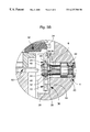
- FIG. 2 is a cross-section along the line ll—ll of FIG. 1;
- FIGS. 3A to 3 C are detailed views of the zone surrounded by a circle in dot and dash lines in FIG. 2 with the pusher stem in the rest position, respectively pulled out and pushed in.
- the present invention concerns the general inventive idea which consists in providing a push button device allowing the control, from an initial rest position, of for example the operation of a chronograph (start, stop, resetting to zero) in a first pushed in position, and the correction of time related data, a date or other information in a second pulled out position.
- the present push button device is described in its application to a timepiece, in particular a chronograph. It goes without saying however, that it can be applied to any other constructive assembly in which it is sought, by means of a single push button, on the one hand to control the start of an electric or mechanical function, and on the other hand to modify the display of a physical magnitude.
- the push button device As shown in FIGS. 1 and 2, the push button device according to the invention, designated as a whole by the general numerical reference 1 , includes a pusher head 2 held by force, conventionally by being driven into the end of a pusher stem 4 .
- Pusher stem 4 is arranged so as to slide inside a recess 6 of generally cylindrical shape arranged in the middle part 8 of a watch case 10 .
- Stem 4 moves axially in recess 6 against the return force of a spring 12 when a control push is applied to pusher head 2 .
- Return spring 12 is disposed in a recess 14 arranged in pusher head 2 and rests axially on the base 16 of a cavity 18 provided in middle part 8 .
- Pusher stem 4 has in one location in the length thereof an annular groove 20 in which a sealing gasket 22 is housed. Gasket 22 assures the sealing of recess 6 when stem 4 slides therein when push button device 1 according to the invention is activated by a user.
- pusher stem 4 is further able to move axially from its rest position into a second pulled out position when a control traction is exerted on pusher head 2 .
- transmission means 24 are mounted at the end of pusher stem 4 which projects from middle part 8 .
- These transmission means 24 can be constituted for example by a lever or even by a wheel 26 which, according to a simplified variant of the invention, is fixedly mounted on pusher stem 4 .
- wheel 26 is freely mounted on pusher stem 4 and includes resilient means 28 such as a pair of resilient arms 30 which allow the coupling thereof by friction with said pusher stem 4 when the latter is biased into the pulled out correction position as described in detail hereinafter.
- Transmission wheel 26 co-operates with data display correction means 32 such as a second wheel 34 .
- push button device 1 also includes holding means 36 mounted after transmission wheel 26 on pusher stem 24 .
- These holding means 36 such as preferably a key 38 , exerts sufficient force on pusher stem 4 to act against the return force of spring 12 which tends to return pusher stem 4 to the pulled out position and hold the latter in its rest position. Holding means 36 are locked on stem 4 , i.e.
- Holding means 36 thus also assure an indexing function for the axial movement of stem 4 which allows the user to know, as a function of the force which he is compelled to exert to overcome the resistance to deformation of holding means 36 , that said stem 4 is in the required pushed in or pulled out position.
- transmission wheel 26 and key 38 are mounted with a slight axial clearance in a recess 40 arranged in watch case 10 , so that they are practically prevented from sliding axially, but free to move in rotation.
- FIGS. 3A to 3 C we turn now to the operation of push button device 1 according to the invention with reference to FIGS. 3A to 3 C in which pusher stem 4 is shown respectively in its rest, pulled out and pushed in position.
- stem 4 has two circular shoulders 42 and 44 connected to said stem 4 by two truncated ramps respectively 46 and 48 separated by an annular groove 50 .
- transmission wheel 26 In the rest position of pusher stem 4 (FIG. 3 A), transmission wheel 26 is idle around annular groove 50 . However, when stem 4 is pulled (FIG. 3 B), transmission wheel 26 substantially prevented from sliding axially in recess 40 , is coupled by friction by its resilient arms 30 onto shoulder 42 , this movement of engagement being facilitated by the presence of ramp 44 . At this moment, the user can correct time related data, a date or other information simply by rotating pusher head 2 to the left or right. Finally, when the user exerts a control push on pusher head 2 (FIG. 3 C), transmission wheel 26 is again idle around pusher stem 4 , which acts by the terminal end thereof on a control device 52 such as a spring or an electric contact part controlling, for example, the start, stop or resetting to zero of a chronograph.
- a control device 52 such as a spring or an electric contact part controlling, for example, the start, stop or resetting to zero of a chronograph.
- transmission wheel 26 when transmission wheel 26 is fixedly mounted on pusher stem 4 , it co-operates with a toothing of correction wheel 34 in the pulled out position of pusher stem 4 , it being understood that in the rest position or pushed in position of said stem 4 , this same transmission wheel 26 is released from the toothing of correction wheel 34 .
Landscapes
- Physics & Mathematics (AREA)
- General Physics & Mathematics (AREA)
- Electric Clocks (AREA)
- Measurement Of Unknown Time Intervals (AREA)
Abstract
The invention concerns a push button device for a timepiece, in particular a chronograph, including a pusher head (2) associated with a pusher stem (4) arranged so as to slide in a recess (6) inside which it moves axially from a rest position against the resilient return force of a spring (12) when the pusher head (2) is pushed in, characterised in that the pusher stem (4) is also able to move axially from its rest position to a pulled out position when the pusher head (2) is pulled out.
Description
The present invention concerns a push button device for a timepiece used, for example, to start a chronograph in the pushed in position, and allowing time data or a date to be corrected in a pulled out position.
A timesetting device for an electronic watch including a push button having a shape such that it allows the device to he actuated by a user is known from Swiss Patent No. 577 701. The push button comprises a pusher head which is driven onto a pusher stem and held thereon said stem allowing a timesetting device to be actuated. Inside the pusher head is arranged a recess of generally cylindrical shape in which is disposed a return spring which bias the pusher head axially towards an initial rest position. The pusher stem carries a crown which, when the user presses on the pusher head, engages in a recess of a timesetting element attached to the movement of the watch. This element allows high frequency pulses to be supplied to the hour and minute indicators driving means of the watch. The sole function of the push button device disclosed in this Patent is to allow timesetting. Further, it applies to an electronic watch.
Swiss Patent No. 506 115 also discloses a time correcting device for a watch whose pinion and timesetting stem have an axis of rotation perpendicular to the plane of the watch movement, which rules out a chronograph function since the user is obliged to act on the pinion via the back face of the watch case. Moreover, the indexing function of the timesetting stem is defined by a spring attached to the case and co-operating with said stem.
Further, Swiss Patent No. 3647 discloses a timesetting mechanism for a watch including a timesetting pinion, a winding pinion and a timesetting stem. The timesetting stem is provided with a square section via which it engages the winding pinion when it is in the pushed in position, and the timesetting pinion when it is in the pulled out position. This is not a push button device, but a simple timesetting stem with two coaxial pinions.
An object of the present invention is to provide a push button device for a timepiece allowing the control, from an initial rest position, for example of the start command of a chronograph in a first pushed in position of the push button, and the correction of time related data or a date in a second pulled out position of said push button.
The present invention thus concerns a push button device for a timepiece, in particular a chronograph, including a pusher head associated with a pusher stem arranged so as to slide in a recess inside which it moves axially from a rest position against the return force of a spring when the pusher head is pushed in, characterised in that the pusher stem is also able to move axially from its rest position to a pulled out position when the pusher head is pulled out.
Acccording to an additional feature of the invention, the push button device includes transmission means co-operating with correction means in the pulled out position of the pusher head.
As a result of these features, the present invention provides a push button device by means of which the user can, either, control the start command for example of a chronograph, or adjust the display of time related data (present time, alarm time, etc.) or a date.
According to another advantage of the invention, correction of the data can be performed in an identical manner in either of the left or right rotational directions of the pusher head, which allows one to avoid the risk of errors which affect conventional correction systems in which, depending on the direction in which the adjustment pinion is rotated, data of a first type (for example time data) or data of a second type (for example a date) is modified. Further, it should be noted that data correction can be performed while the chronograph is working. Finally, by proposing combining the chronograph and data correcting or setting functions by means of a single push button device, the invention provides a constructive assembly which is simpler to manufacture and thus less expensive.
According to another feature of the invention, the push button device includes holding means acting against the return force of the spring which tend to return the pusher stem into the pulled out position.
Other features and advantages of the present invention will appear more clearly upon reading the following detailed description of an embodiment example of a push button device according to the invention, this example being given solely by way of illustrative and non limiting example, in conjunction with the annexed drawings, in which:
FIG. 1 is a partial top view of a watch case, torn away in the zone of the push button device according to the invention;
FIG. 2 is a cross-section along the line ll—ll of FIG. 1; and
FIGS. 3A to 3C are detailed views of the zone surrounded by a circle in dot and dash lines in FIG. 2 with the pusher stem in the rest position, respectively pulled out and pushed in.
The present invention concerns the general inventive idea which consists in providing a push button device allowing the control, from an initial rest position, of for example the operation of a chronograph (start, stop, resetting to zero) in a first pushed in position, and the correction of time related data, a date or other information in a second pulled out position. The present push button device is described in its application to a timepiece, in particular a chronograph. It goes without saying however, that it can be applied to any other constructive assembly in which it is sought, by means of a single push button, on the one hand to control the start of an electric or mechanical function, and on the other hand to modify the display of a physical magnitude.
As shown in FIGS. 1 and 2, the push button device according to the invention, designated as a whole by the general numerical reference 1, includes a pusher head 2 held by force, conventionally by being driven into the end of a pusher stem 4. Pusher stem 4 is arranged so as to slide inside a recess 6 of generally cylindrical shape arranged in the middle part 8 of a watch case 10. Stem 4 moves axially in recess 6 against the return force of a spring 12 when a control push is applied to pusher head 2.
According to a first feature of the invention, pusher stem 4 is further able to move axially from its rest position into a second pulled out position when a control traction is exerted on pusher head 2.
According to an additional feature of the invention, transmission means 24 are mounted at the end of pusher stem 4 which projects from middle part 8. These transmission means 24 can be constituted for example by a lever or even by a wheel 26 which, according to a simplified variant of the invention, is fixedly mounted on pusher stem 4. Nonetheless, according to the preferred embodiment of the invention, wheel 26 is freely mounted on pusher stem 4 and includes resilient means 28 such as a pair of resilient arms 30 which allow the coupling thereof by friction with said pusher stem 4 when the latter is biased into the pulled out correction position as described in detail hereinafter. Transmission wheel 26 co-operates with data display correction means 32 such as a second wheel 34. Thus, when the user rotates pusher head 2 to the left or right to correct time related data, a date or other information, transmission wheel 26, coupled with stem 4, drives correction wheel 34.
According to another feature of the invention, push button device 1 also includes holding means 36 mounted after transmission wheel 26 on pusher stem 24. These holding means 36 such as preferably a key 38, exerts sufficient force on pusher stem 4 to act against the return force of spring 12 which tends to return pusher stem 4 to the pulled out position and hold the latter in its rest position. Holding means 36 are locked on stem 4, i.e. they have sufficient elasticity to allow the forced passage of pusher stem 4 when the user exerts a control push or traction on pusher head 2 Holding means 36 thus also assure an indexing function for the axial movement of stem 4 which allows the user to know, as a function of the force which he is compelled to exert to overcome the resistance to deformation of holding means 36, that said stem 4 is in the required pushed in or pulled out position.
According to an additional feature of the invention, transmission wheel 26 and key 38 are mounted with a slight axial clearance in a recess 40 arranged in watch case 10, so that they are practically prevented from sliding axially, but free to move in rotation.
We turn now to the operation of push button device 1 according to the invention with reference to FIGS. 3A to 3C in which pusher stem 4 is shown respectively in its rest, pulled out and pushed in position. As is clear from these Figures, towards the free end thereof which projects from middle part 8, stem 4 has two circular shoulders 42 and 44 connected to said stem 4 by two truncated ramps respectively 46 and 48 separated by an annular groove 50.
In the rest position of pusher stem 4 (FIG. 3A), transmission wheel 26 is idle around annular groove 50. However, when stem 4 is pulled (FIG. 3B), transmission wheel 26 substantially prevented from sliding axially in recess 40, is coupled by friction by its resilient arms 30 onto shoulder 42, this movement of engagement being facilitated by the presence of ramp 44. At this moment, the user can correct time related data, a date or other information simply by rotating pusher head 2 to the left or right. Finally, when the user exerts a control push on pusher head 2 (FIG. 3C), transmission wheel 26 is again idle around pusher stem 4, which acts by the terminal end thereof on a control device 52 such as a spring or an electric contact part controlling, for example, the start, stop or resetting to zero of a chronograph.
It is also seen in FIGS. 3A to 3C that key 38 abuts against a wall 54 of recess 40, so that it generates sufficient force to act against the return force of spring 12 which tends to return pusher stem 4 into the pulled out position and to hold the latter in its rest position. Moreover, when the user pulls or pushes stem 4, key 38 deforms elastically to allow the forced passage of shoulder 42, this engagement movement being facilitated by truncated ramp 46. The axial movement indexing function for stem 4 described hereinbefore is thus achieved.
It goes without saying that various simple modifications and variants fall within the scope of the present invention. It will be understood in particular that when transmission wheel 26 is fixedly mounted on pusher stem 4, it co-operates with a toothing of correction wheel 34 in the pulled out position of pusher stem 4, it being understood that in the rest position or pushed in position of said stem 4, this same transmission wheel 26 is released from the toothing of correction wheel 34.
Claims (10)
1. A push button device for a timepiece including a pusher head held into an end of a pusher stem arranged so as to slide in a recess inside which said pusher stem moves axially from a rest position against the resilient return force of a spring when the pusher head is pushed in, wherein the pusher stem is also able to move axially from its rest position into a pulled out position when the pusher head is pulled out, and wherein said push button includes transmission means co-operating with correction means in the pulled out position of the pusher stem, said transmission means being freely mounted on the pusher stem and being provided with resilient means to allow the coupling thereof with said pusher stem when the latter is brought into a pulled out correction position.
2. A push button device according to claim 1, wherein the transmission means are formed by a wheel provided with a pair of resilient arms.
3. A push button device according to claim 1, wherein it further includes holding means acting against the return force of the spring which tends to return the pusher stem into the pulled out position.
4. A push button device according to claim 3, wherein the holding means are formed by a key.
5. A push button device according to claim 4, wherein the key is mounted by force on the pusher stem.
6. A push button device according to claim 1, wherein the transmission means and the holding means are arranged in a recess.
7. A push button device according to claim 1, wherein the pusher stem has two shoulders.
8. A push button device according to claim 7, wherein the shoulders are connected to the pusher stem by two truncated ramps respectively.
9. A push button device according to claim 1, wherein in one location in the length thereof the pusher stem has an annular groove in which a sealing gasket is housed.
10. A push button device according to claim 1, wherein the pusher head is driven into the pusher stem and has a recess in which the return spring is housed.
Applications Claiming Priority (2)
| Application Number | Priority Date | Filing Date | Title |
|---|---|---|---|
| CH106298 | 1998-05-13 | ||
| CH1062/98 | 1998-05-13 |
Publications (1)
| Publication Number | Publication Date |
|---|---|
| US6227700B1 true US6227700B1 (en) | 2001-05-08 |
Family
ID=4201569
Family Applications (1)
| Application Number | Title | Priority Date | Filing Date |
|---|---|---|---|
| US09/310,189 Expired - Fee Related US6227700B1 (en) | 1998-05-13 | 1999-05-12 | Push button device for a timepiece, in particular a chronograph |
Country Status (5)
| Country | Link |
|---|---|
| US (1) | US6227700B1 (en) |
| JP (1) | JPH11352255A (en) |
| KR (1) | KR19990088020A (en) |
| CN (1) | CN1235291A (en) |
| TW (1) | TW381193B (en) |
Cited By (9)
| Publication number | Priority date | Publication date | Assignee | Title |
|---|---|---|---|---|
| WO2004042478A2 (en) * | 2002-11-06 | 2004-05-21 | Fore Eagle Co Ltd | Device for coupling a pinion |
| US20100187074A1 (en) * | 2008-12-31 | 2010-07-29 | Suunto Oy | Two-function controlling device for a wrist computer or alike and method for controlling a wrist computer or suchlike terminal |
| US20110235471A1 (en) * | 2010-03-23 | 2011-09-29 | Bright Aggregation Technology Limited | Timepiece with Multi-Functional Actuator |
| CN103995457A (en) * | 2013-02-20 | 2014-08-20 | 精工电子有限公司 | Portable device and portable timepiece |
| US8851743B1 (en) * | 2011-08-23 | 2014-10-07 | Invicta Watch Company Of America, Inc. | Trigger mechanism for a chronograph watch |
| US9086717B2 (en) | 2012-02-13 | 2015-07-21 | Invicta Watch Company Of America, Inc. | Interface for actuating a device |
| USD830217S1 (en) * | 2016-07-18 | 2018-10-09 | Samsung Electronics Co., Ltd. | Portable electronic device |
| USD991817S1 (en) * | 2020-12-07 | 2023-07-11 | Glock Gesellschaft M.B.H. | Watch crown |
| USD996252S1 (en) * | 2021-01-22 | 2023-08-22 | Shenzhen DO Intelligent Technology Co., Ltd. | Crown of smart watch |
Families Citing this family (6)
| Publication number | Priority date | Publication date | Assignee | Title |
|---|---|---|---|---|
| TW455749B (en) * | 1999-09-29 | 2001-09-21 | Swatch Group Man Serv Ag | Multi-function push-button contact clamp |
| JP5025855B2 (en) * | 2001-04-27 | 2012-09-12 | セイコーインスツル株式会社 | Arm portable equipment |
| EP1921516B1 (en) * | 2006-11-09 | 2010-01-13 | ETA SA Manufacture Horlogère Suisse | Assembly component comprising two series of elastic structures and timepiece incorporating this component |
| EP2560054B1 (en) * | 2011-08-17 | 2017-11-15 | ETA SA Manufacture Horlogère Suisse | Winding of a clock mechanism by pressing or pulling |
| US10725429B2 (en) * | 2017-05-24 | 2020-07-28 | Omega Sa | Timepiece containing a locking device for a pusher |
| CN112984502A (en) * | 2021-01-27 | 2021-06-18 | 杭州聚能环保科技股份有限公司 | Micro-discharge pulverized coal combustion system |
Citations (7)
| Publication number | Priority date | Publication date | Assignee | Title |
|---|---|---|---|---|
| US1926243A (en) * | 1930-09-05 | 1933-09-12 | Russo Nicola | Universal clock |
| US3377796A (en) * | 1966-03-11 | 1968-04-16 | Hamilton Watch Co | Electric watch calendar setting mechanism |
| CH470704A (en) * | 1965-07-14 | 1969-05-14 | Piquerez Sa Ervin | Watch comprising a rotating crown, mounted under the glass |
| US4536095A (en) | 1984-09-13 | 1985-08-20 | Timex Corporation | Crown setting switch for a wristwatch |
| US4932011A (en) | 1989-11-06 | 1990-06-05 | Timex Corporation | Three hand movement for a timepiece with improved timesetting gear train |
| EP0392307A1 (en) | 1989-04-12 | 1990-10-17 | Eta SA Fabriques d'Ebauches | Push-button, in particular for watch-case |
| EP0655664A1 (en) | 1993-11-25 | 1995-05-31 | SMH Management Services AG | Winding-button with push-piece for a timepiece |
-
1999
- 1999-05-03 KR KR1019990015829A patent/KR19990088020A/en not_active Application Discontinuation
- 1999-05-07 TW TW088107488A patent/TW381193B/en not_active IP Right Cessation
- 1999-05-12 US US09/310,189 patent/US6227700B1/en not_active Expired - Fee Related
- 1999-05-13 CN CN99106488A patent/CN1235291A/en active Pending
- 1999-05-13 JP JP11132450A patent/JPH11352255A/en active Pending
Patent Citations (9)
| Publication number | Priority date | Publication date | Assignee | Title |
|---|---|---|---|---|
| US1926243A (en) * | 1930-09-05 | 1933-09-12 | Russo Nicola | Universal clock |
| CH470704A (en) * | 1965-07-14 | 1969-05-14 | Piquerez Sa Ervin | Watch comprising a rotating crown, mounted under the glass |
| US3377796A (en) * | 1966-03-11 | 1968-04-16 | Hamilton Watch Co | Electric watch calendar setting mechanism |
| US4536095A (en) | 1984-09-13 | 1985-08-20 | Timex Corporation | Crown setting switch for a wristwatch |
| EP0392307A1 (en) | 1989-04-12 | 1990-10-17 | Eta SA Fabriques d'Ebauches | Push-button, in particular for watch-case |
| US5043958A (en) * | 1989-04-12 | 1991-08-27 | Eta Sa Fabriques D'ebauches | Push button assembly particularly for a watchcase |
| US4932011A (en) | 1989-11-06 | 1990-06-05 | Timex Corporation | Three hand movement for a timepiece with improved timesetting gear train |
| EP0655664A1 (en) | 1993-11-25 | 1995-05-31 | SMH Management Services AG | Winding-button with push-piece for a timepiece |
| US5521890A (en) * | 1993-11-25 | 1996-05-28 | Smh Management Services Ag | Push-piece crown for a timepiece |
Cited By (13)
| Publication number | Priority date | Publication date | Assignee | Title |
|---|---|---|---|---|
| WO2004042478A3 (en) * | 2002-11-06 | 2004-09-02 | Fore Eagle Co Ltd | Device for coupling a pinion |
| WO2004042478A2 (en) * | 2002-11-06 | 2004-05-21 | Fore Eagle Co Ltd | Device for coupling a pinion |
| US20100187074A1 (en) * | 2008-12-31 | 2010-07-29 | Suunto Oy | Two-function controlling device for a wrist computer or alike and method for controlling a wrist computer or suchlike terminal |
| US8371745B2 (en) | 2008-12-31 | 2013-02-12 | Suunto Oy | Two-function controlling device for a wrist computer or alike and method for controlling a wrist computer or suchlike terminal |
| US20110235471A1 (en) * | 2010-03-23 | 2011-09-29 | Bright Aggregation Technology Limited | Timepiece with Multi-Functional Actuator |
| US8439559B2 (en) * | 2010-03-23 | 2013-05-14 | Bright Aggregation Technology Limited | Timepiece with multi-functional actuator |
| US8851743B1 (en) * | 2011-08-23 | 2014-10-07 | Invicta Watch Company Of America, Inc. | Trigger mechanism for a chronograph watch |
| US9086717B2 (en) | 2012-02-13 | 2015-07-21 | Invicta Watch Company Of America, Inc. | Interface for actuating a device |
| CN103995457A (en) * | 2013-02-20 | 2014-08-20 | 精工电子有限公司 | Portable device and portable timepiece |
| CN103995457B (en) * | 2013-02-20 | 2017-10-24 | 精工电子有限公司 | Portable equipment and portable watch |
| USD830217S1 (en) * | 2016-07-18 | 2018-10-09 | Samsung Electronics Co., Ltd. | Portable electronic device |
| USD991817S1 (en) * | 2020-12-07 | 2023-07-11 | Glock Gesellschaft M.B.H. | Watch crown |
| USD996252S1 (en) * | 2021-01-22 | 2023-08-22 | Shenzhen DO Intelligent Technology Co., Ltd. | Crown of smart watch |
Also Published As
| Publication number | Publication date |
|---|---|
| CN1235291A (en) | 1999-11-17 |
| JPH11352255A (en) | 1999-12-24 |
| KR19990088020A (en) | 1999-12-27 |
| TW381193B (en) | 2000-02-01 |
Similar Documents
| Publication | Publication Date | Title |
|---|---|---|
| US6227700B1 (en) | Push button device for a timepiece, in particular a chronograph | |
| US7244062B2 (en) | Device for stopping the balance during the time-setting of a tourbillon watch | |
| US5742565A (en) | Crown setting device for a timepiece | |
| US7065005B2 (en) | Timepiece such as a wristwatch including an alarm mechanism | |
| US3983691A (en) | Winding and setting mechanism for watch movements | |
| JP5536623B2 (en) | Chronograph clock | |
| JP4244643B2 (en) | Clock with chronograph | |
| US7232254B2 (en) | Chronograph-type watch | |
| US4104866A (en) | Timepiece | |
| US7001064B2 (en) | Push-piece control device for a watch | |
| US6126309A (en) | Simplified time-setting device for a timepiece | |
| JP7473300B2 (en) | Clock Display System | |
| US4234943A (en) | Month correcting mechanism for calendar timepieces | |
| CN110753884B (en) | Crown pusher assembly and wrist-worn electronic device including same | |
| US20240077834A1 (en) | Member for controlling a plurality of functions of a timepiece movement | |
| US7780341B2 (en) | Clockwork movement | |
| KR20230091792A (en) | Multifunction correction device for a timepiece and timepiece comprising such a multifunction correction device | |
| US4127985A (en) | Watch | |
| US6247841B1 (en) | Device for actuating a mechanism for a watch case of non circular shape | |
| US4744068A (en) | Timepiece setting arrangement including a safety lock | |
| US7070320B2 (en) | Mechanism for triggering a striking work for a timepiece fitted with a timer | |
| US3739570A (en) | Column-wheel timer | |
| JPH1123741A (en) | Chronograph timepiece | |
| US11822291B2 (en) | Watch equipped with a device for locking an external control unit | |
| JP2005003493A (en) | Electronic timepiece |
Legal Events
| Date | Code | Title | Description |
|---|---|---|---|
| AS | Assignment |
Owner name: ETA SA FABRIQUES D'EBAUCHES, SWITZERLAND Free format text: ASSIGNMENT OF ASSIGNORS INTEREST;ASSIGNORS:HUNZIKER,YANNICK;NUSSBAUM,ANDRE;REBEAUD,JEAN-PHILIPPE;REEL/FRAME:009965/0770 Effective date: 19990412 |
|
| REMI | Maintenance fee reminder mailed | ||
| LAPS | Lapse for failure to pay maintenance fees | ||
| STCH | Information on status: patent discontinuation |
Free format text: PATENT EXPIRED DUE TO NONPAYMENT OF MAINTENANCE FEES UNDER 37 CFR 1.362 |
|
| FP | Lapsed due to failure to pay maintenance fee |
Effective date: 20050508 |