US6178741B1 - Mems synthesized divert propulsion system - Google Patents
Mems synthesized divert propulsion system Download PDFInfo
- Publication number
- US6178741B1 US6178741B1 US09/173,923 US17392398A US6178741B1 US 6178741 B1 US6178741 B1 US 6178741B1 US 17392398 A US17392398 A US 17392398A US 6178741 B1 US6178741 B1 US 6178741B1
- Authority
- US
- United States
- Prior art keywords
- recited
- propulsion system
- synthesized
- wafer
- divert
- Prior art date
- Legal status (The legal status is an assumption and is not a legal conclusion. Google has not performed a legal analysis and makes no representation as to the accuracy of the status listed.)
- Expired - Fee Related
Links
Images


Classifications
-
- B—PERFORMING OPERATIONS; TRANSPORTING
- B64—AIRCRAFT; AVIATION; COSMONAUTICS
- B64G—COSMONAUTICS; VEHICLES OR EQUIPMENT THEREFOR
- B64G1/00—Cosmonautic vehicles
- B64G1/22—Parts of, or equipment specially adapted for fitting in or to, cosmonautic vehicles
- B64G1/24—Guiding or controlling apparatus, e.g. for attitude control
- B64G1/26—Guiding or controlling apparatus, e.g. for attitude control using jets
-
- F—MECHANICAL ENGINEERING; LIGHTING; HEATING; WEAPONS; BLASTING
- F42—AMMUNITION; BLASTING
- F42B—EXPLOSIVE CHARGES, e.g. FOR BLASTING, FIREWORKS, AMMUNITION
- F42B10/00—Means for influencing, e.g. improving, the aerodynamic properties of projectiles or missiles; Arrangements on projectiles or missiles for stabilising, steering, range-reducing, range-increasing or fall-retarding
- F42B10/60—Steering arrangements
- F42B10/66—Steering by varying intensity or direction of thrust
- F42B10/661—Steering by varying intensity or direction of thrust using several transversally acting rocket motors, each motor containing an individual propellant charge, e.g. solid charge
Definitions
- the present invention relates to a divert propulsion system and more particularly to a method and apparatus to forming a synthesized divert propulsion system from microelectromechanical system (MEMS) technology.
- MEMS microelectromechanical system
- Various vehicles including kill vehicles, interceptors, rockets and missiles are known for intercepting and destroying various airborne threats or targets, such as missiles, rockets and the like. Examples of such systems are disclosed in U.S. Pat. Nos. 4,211,378; 5,533,331 and 5,710,423.
- Such vehicles are known to include divert propulsion systems which are used to produce thrusts in a direction generally orthogonal to the longitudinal axis and velocity vector of the vehicle. The divert maneuvers are used to enhance the kill or intercept probability of the vehicle relative to a particular target. Both spinning and non-spinning vehicles are known.
- Such divert propulsion systems are under the control of a control system which receives data regarding the trajectory and distance of the target relative to the vehicle in order to determine the amount of divert propulsion to intercept the target.
- FIGS. 1 and 2 An exemplary divert propulsion system, formed from discrete components and subsystems, is illustrated in FIGS. 1 and 2.
- FIGS. 1 and 2 There are many known disadvantages associated with known divert propulsion systems as illustrated in FIGS. 1 and 2. For example, the number of components required for the system is relatively large; typically around 30 . Moreover, the systems are relatively complex and are known to include pressurization subsystems and components, propellant storage and feed subsystems and components, as well as a control and a divert thruster subsystem. Assembly of the components into a functional system requires relatively complex designs with structural, thermal, mechanical and electrical interconnections for attachment for heat, fluid and electric conduction. Interconnecting tubing and cabling is also known to be relatively complex requiring many joints, fittings, connectors, tie-downs and the like.
- Such known divert propulsion systems are also known to have various design constraints. For example, such systems result in additional designs and fabrication complexity due to the interaction of the propulsion components and subsystems with other vehicle components and subsystems, such as seekers, IMUs, electronics, cabling, actuators and the like. Thus, there is a need for a simplified divert propulsion system which is less complex than known divert propulsion systems.
- the present invention relates to a synthesized divert propulsion system adapted to be utilized in various vehicles, including kill vehicles, interceptors, rockets, missiles and the like.
- the system is amenable to being fabricated using microelectromechanical system (MEMS) technology which eliminates complex interconnections required for traditional divert propulsion systems by integrating all propulsion fluid functions and all controlled electronic functions onto a plurality of wafers.
- MEMS microelectromechanical system
- the wafers are integrated into a complete synthesized divert propulsion system by stacking and bonding the wafers together.
- FIG. 1 is a schematic diagram of a known divert propulsion system.
- FIG. 2 is a layout diagram of a known divert propulsion system illustrated in FIG. 1 .
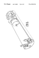
- FIG. 3 is an exploded perspective view of the synthesized divert propulsion system illustrated in accordance with the present invention.
- FIG. 4 is a plan view of a thruster wafer in accordance with the present invention.
- FIG. 5 is an end-view of the thruster wafer illustrated in FIG. 4 .
- FIG. 6 is a sectional view along line A—A of FIG. 4 .
- FIG. 7 is a partial sectional view illustrating a thrust chamber formed in the thruster wafer illustrated in FIG. 4 .
- FIG. 8 and FIG. 8A illustrate and various methods for forming an electronics wafer in accordance with the present invention.
- FIG. 9 is a plan view of a thruster nozzle ring in accordance with the present invention.
- FIG. 10 is an end view of the thruster nozzle ring illustrated in FIG. 9 .
- FIG. 11 is a sectional view of the thruster nozzle ring along line A—A of FIG. 10 .
- FIG. 12 is a partial sectional view illustrating a nozzle formed in the thruster nozzle ring in accordance with the present invention.
- FIG. 13 is a plan view of a charge up wafer in accordance with the present invention.
- FIG. 14 is an end view of the charge cup wafer illustrated in FIG. 13 .
- FIG. 15 is a plan view of an electronics wafer in accordance with the present invention.
- FIG. 16 is an end view of the electronics wafer illustrated in FIG. 15 .
- FIG. 17 is an exemplary block diagram of an exemplary thruster control system in accordance with the present invention.
- the synthesized divert propulsion system in accordance with the present invention offers many advantages over known divert propulsion systems.
- the synthesized divert propulsion system in accordance with the present invention eliminates the relatively complex interconnections required in traditional divert propulsion systems by integrating all propulsion fluid functions and all control of electronic functions into wafers. These wafers are then integrated into complete synthesized functional divert propulsion system by stacking and bonding the wafers together.
- An important aspect of the invention is that the wafers are amenable to being formed by known microelectromechanical system (MEMS) fabrication technology. Since MEMS fabrication technology is inheritantly an electronic based planar method of design, the propulsion components can be fabricated as wafers and joined together by various methods including anodic and polymeric bonding. The use of mechanical fasteners and connectors is thus eliminated.
- MEMS microelectromechanical system
- the synthesized divert propulsion system in accordance with the present invention is generally identified with the reference numeral 20 .
- the synthesized divert propulsion system 20 is adapted to be utilized in various vehicles, including kill vehicles, interceptors, rockets, missiles and the like.
- the system 20 includes a thruster nozzle ring 22 , a thrust chamber wafer 24 , a charge cup wafer 26 and an electronics wafer 28 .
- the thruster nozzle ring 22 , thrust chamber wafer 24 , charge cup wafer 26 and the electronics wafer 28 are stacked together concentrically and bonded together, for example, by anodic or polymeric bonding to form a synthesized divert propulsion system 20 as shown.
- FIGS. 4-7 An exemplary thrust chamber wafer 24 is illustrated in FIGS. 4-7.
- the thrust chamber wafer 24 is illustrated with an exemplary number of 64 thrusters.
- the thrust chamber wafer 24 is formed from high strength, low density metal, such as aluminum or titanium, plastic, silicon or ceramic material into a ring with a plurality of evenly spaced thruster chambers 30 , for example, generally conically shaped thruster chambers, radially disposed adjacent the outside diameter of the thrust chamber wafer 24 .
- Each thruster chamber 30 is adapted to carry a pyrotechnic powder, liquid or gelled liquid propellant (not shown).
- a pilot hole 32 is provided in each of the thruster chambers 30 . The pilot holes 32 are used for enabling detonation of the propellant within the thruster chambers 30 .
- the thruster nozzle ring 22 (FIG. 3) is formed as a ring with a slightly larger outer diameter than the thrust chamber wafer 24 and is adapted to fit over the thrust chamber wafer 24 .
- the thruster nozzle ring 22 is formed with a plurality of radially disposed equally spaced nozzles 33 , for example, formed in a generally conical shape, configured to correspond with the thruster chambers 30 .
- conical shaped nozzles are provided.
- the nozzle ring 20 also includes an aluminum seal which forms a burst disc for each thruster chamber 30 .
- the thruster nozzle ring may be formed from high strength, low density metal, such as aluminum or titanium, plastic, silicon, or ceramic, and is adapted to be shrink fit over the thrust chamber wafer 24 forming a supersonic nozzle and a burst disc for each thrust chamber 30 .
- a charge cup wafer 26 is secured to the thrust chamber wafer 24 , for example by bonding.
- the charge cup wafer 26 may be formed from high strength, low density metal, such as aluminum or titanium, silicon or ceramic.
- the charge cup wafer 26 includes a plurality of radially disposed cylinders 34 for holding a pyrotechnic initiation propellant (not shown).
- the charge cup wafer 26 is configured such that the cylinders 34 are configured to correspond to the thruster chambers 30 on the thrust chamber wafer 24 .
- the charge cup wafer 26 is configured such that the individual cylinders 34 are in communication with the pilot holes 32 in the thrust chambers 30 and 24 .
- the cylinders 34 with the pyrotechnic initiation propellant are used to ignite the propellant in the thrust chamber 30 formed on the thrust chamber wafer 24 .
- the pyrotechnic initiation propellant is detonated by an electronic control circuit which is part of the electronics wafer 28 discussed below.
- the electronics wafer 28 may include the timing, bookkeeping and control digital electronics as well as an analog firing circuit including semi-conductor bridge wire initiators and sensors for detonation of the thruster chambers and the thrust chamber wafer 24 .
- the electronics wafer 28 may be formed by hybrid multi-chip module (MCM) processing or by wafer scale integration (WSI). In monolithic WSI processing, a complete electronic system is fabricated as a single large circuit die. With WSI processing, all integrated circuits and components produced are generated by a single process.
- MCM module achieves many of the same benefits of the WSI module by combining many integrated circuits onto a common host substrate.
- the advantages of MCM over WSI processing includes the ability to use dies produced from a variety of methods most amenable to the dies function and the ability to screen individual dies for defects.
- MCM substrate types include ceramic, silicon or laminates, all of which have distinct characteristics and advantages.
- the electronics wafer 28 contains all the digital processing and analog power and firing circuitry including low power semi-conductor bridewire (SCB) initiators used as thruster initiators for detonating the pyrotechnic initiation propellant contained in the charge cup wafer cylinders 34 .
- SCB semi-conductor bridewire
- the SCB initiator action times are relatively repeatable and require, for example, only 300 microjoules of electrical energy for initiation resulting in relatively small battery sizes.
- Digital signal processing may be implemented utilizing in-circuit programmable field programmable gate arrays (FPGA) chips, which allow for onboard programming and reprogramming of digital functions eliminating significant costs and schedule impact for chip foundry fabrication and refabrication when changes are made.
- FPGA field programmable gate arrays
- a block diagram of the thruster control circuit 40 is integrated onto the electronics wafer 28 as illustrated in FIG. 17 .
- Control of the thruster firing to divert a vehicle assumes that the vehicle is spinning around the thruster ring axis to permit each thruster to reach the firing angle at a time related to the spin rate.
- the control logic 40 may be embedded in a field programmable gate array (FPGA) 42 and use the timing and distance-off-center information from a conventional tracking sensor 44 to determine when during the vehicle rotation a thruster must fire to bring the vehicle axis in line with the target.
- the rotation timing can be determined by counting sensor timing pulses or by converting accelerometer data 46 into digital format using an analog to digital converter 48 , with a digital phase locked oscillator (not shown) in the FPGA.
- a high frequency reference clock 50 may be used to synthesize a rotationally synchronized clock for accurate timing measurements.
- a small memory in the FPGA 42 may be used to keep track of the thrusters fired so that the control logic 40 ensures that they are fired on alternate sides of the vehicle so as to maintain balance.
- the initiators are preferably ignited in a relatively balanced manner to achieve a divert thrust.
- the distance-off-axis information from the sensor 44 may be used to determine how long to wait before firing the next thruster. The more off axis the target is, the sooner the next firing would have to be.
- the FPGA 42 may be used to provide all of the fire control and safing functions and would therefore require many I/O connections. Multiple FPGAs 42 could be also used and if used in pairs would aid in balancing the vehicle.
- the power source for the system may be part of the vehicle or be located on a MEMS substrate in the form of coin cell batteries 52 in series.
- the batteries 52 must produce low voltage for the logic (typically 5 V or 3.3 V) and higher voltages on the order of 15 to 20 volts for rapid firing of the initiators 54 .
- a low voltage regulator 56 which may consist of a single chip, can be used to provide conditioned power for the logic and control circuitry 40 .
- a simple charge pumped voltage doubler circuit 58 may be used to increase the battery voltage to the level needed for the initiators 60 , which require a high voltage and high current (4 to 6 amps) to fire rapidly enough to make timing practical.
- capacitor bank 62 Since small batteries do not produce currents this high, it is necessary to accumulate the energy over a longer time in a capacitor bank 62 so that higher currents of much shorter duration can be produced.
- the capacitor bank 62 must be sized so that the voltage across the initiator 60 not droop by more than 30% while the initiator is burning open. This necessitates that the capacitor bank 10 store at least 10 times as much energy as a single initiator needs to open. Assuming an initiator requires 300 microjoules of energy, the estimated amount of capacitance needed to produce the higher currents would need to be at least 15 microfarads—a sizeable capacitor. Since only one initiator 60 is fired at a time, a shared capacitor bank 62 made up of many smaller capacitors in parallel and connected with a high current trace would permit the use of much smaller capacitors distributed evenly around the MEMS substrate.
- the actual firing of the initiators 60 may be accomplished by using a high current metal oxide semiconductor field effect transistor (MOSFET) transistor, silicon controlled rectifier (SCR), or bipolar transistor 64 .
- MOSFET metal oxide semiconductor field effect transistor
- SCRs and bipolar transistors require additional circuitry and higher trigger energies to turn them on.
- High current, low on-resistance MOSFETs 64 are available that require no additional circuitry other than a logic level to turn them on.
- Each initiator 60 would preferably have a dedicated MOSFET high current driver 64 to fire it, which would, in turn, be controlled directly from the FPGA output.
- a depletion mode field effect transistor (FET) with a separate control circuit may be used as a safing clamp 66 to prevent accidental turn on of the MOSFET driver 64 .
- FET depletion mode field effect transistor
- a depletion mode FET transistor is normally on until a pinch-off voltage turns it off.
- the FET transistor is connected across the gate-source connection on the MOSFET, effectively shorting out any noise pulse that might turn on the MOSFET earlier than desired.
- the FPGA 42 is used to signal the safing clamp 66 to release the gate of the MOSFET just before the firing pulse would be sent to the MOSFET.
- the various wafers 22 , 24 , 26 and 28 are amendable to being fabricated using microelectromechanical system (MEMS) technology.
- MEMS microelectromechanical system
- Each wafer 22 , 24 , 26 , and 28 is fabricated utilizing processes which provide the lowest cost and highest operational performance.
- the electronics wafer 28 may be fabricated in one of two ways utilizing either a multi-chip module (MCM) approach or wafer scale integration (WSI) approach.
- MCM requires fabrication of individual chips such as accelerometers, IMUs, FPGAs and SCBs from several different wafers utilizing a variety of electronics process technologies. These chips are then bonded onto a common host substrate which can include ceramic, silicon, or laminates.
- the substrate is metallized with current carrying paths and the chips are wire bonded to these paths to complete the circuit.
- the substrate is formed using hot pressing techniques and is machined using diamond tool machining processes, ultrasonic processes, water jet cutting and laser cutting.
- the individual chips are fabricated using traditional chip manufacturing processes such as MOS (metal oxide semiconductor), CMOS (complimentary metal oxide semiconductor), SOS (silicon on sapphire), and POLY (polysilicon on silicon).
- WSI requires fabrication of a complete functional electronics system on a single large integrated circuit die.
- monolithic WSI has all components such as accelerometers, IMUs, FPGAs and SCBs fabricated using the same process which include MOS, CMOS, SOS or POLY.
- the charge cup wafer 26 and thruster wafer 24 can be fabricated from lightweight metals, composites, plastics or silicon. Each of these materials has advantages and trade-offs in relation to cost, manufacturability, weight and volume. These materials are machined using traditional manufacturing methods and, in the case of silicon, using electronic manufacturing methods.
- the individual wafers are then bonded together using epoxies or anodic bonding techniques.
Landscapes
- Engineering & Computer Science (AREA)
- Remote Sensing (AREA)
- Chemical & Material Sciences (AREA)
- Combustion & Propulsion (AREA)
- Radar, Positioning & Navigation (AREA)
- Aviation & Aerospace Engineering (AREA)
- Physics & Mathematics (AREA)
- Fluid Mechanics (AREA)
- General Engineering & Computer Science (AREA)
- Micromachines (AREA)
- Pressure Sensors (AREA)
- Container, Conveyance, Adherence, Positioning, Of Wafer (AREA)
Abstract
Description
Claims (30)
Priority Applications (4)
| Application Number | Priority Date | Filing Date | Title |
|---|---|---|---|
| US09/173,923 US6178741B1 (en) | 1998-10-16 | 1998-10-16 | Mems synthesized divert propulsion system |
| AU52591/99A AU718680B1 (en) | 1998-10-16 | 1999-10-01 | MEMS synthesized divert propulsion system |
| IL13221899A IL132218A0 (en) | 1998-10-16 | 1999-10-05 | Mems synthesized divert propulsion system |
| EP99120564A EP0994325A3 (en) | 1998-10-16 | 1999-10-15 | Micro-electromechanical nozzle propulsion system |
Applications Claiming Priority (1)
| Application Number | Priority Date | Filing Date | Title |
|---|---|---|---|
| US09/173,923 US6178741B1 (en) | 1998-10-16 | 1998-10-16 | Mems synthesized divert propulsion system |
Publications (1)
| Publication Number | Publication Date |
|---|---|
| US6178741B1 true US6178741B1 (en) | 2001-01-30 |
Family
ID=22634080
Family Applications (1)
| Application Number | Title | Priority Date | Filing Date |
|---|---|---|---|
| US09/173,923 Expired - Fee Related US6178741B1 (en) | 1998-10-16 | 1998-10-16 | Mems synthesized divert propulsion system |
Country Status (4)
| Country | Link |
|---|---|
| US (1) | US6178741B1 (en) |
| EP (1) | EP0994325A3 (en) |
| AU (1) | AU718680B1 (en) |
| IL (1) | IL132218A0 (en) |
Cited By (17)
| Publication number | Priority date | Publication date | Assignee | Title |
|---|---|---|---|---|
| US20030122032A1 (en) * | 2000-05-25 | 2003-07-03 | O'dwyer James Michael | Directional control of missiles |
| US20040084564A1 (en) * | 2002-11-04 | 2004-05-06 | John Lawrence E. | Low mass flow reaction jet |
| US20040245371A1 (en) * | 2003-04-07 | 2004-12-09 | Toshiharu Fujita | Three-axis attitude control propulsion device and flying object comprising the same |
| US20070063095A1 (en) * | 2005-09-16 | 2007-03-22 | Bittle David A | Trajectory correction kit |
| US20080258004A1 (en) * | 2004-07-05 | 2008-10-23 | Joseph Hasson | Exo Atmospheric Intercepting System and Method |
| US20090072076A1 (en) * | 2006-03-07 | 2009-03-19 | Raytheon Company | System and method for attitude control of a flight vehicle using pitch-over thrusters |
| US7692127B1 (en) * | 2007-03-26 | 2010-04-06 | The United States Of America As Represented By The Secretary Of The Navy | MEMS type thermally actuated out-of-plane lever |
| US20110204177A1 (en) * | 2010-02-25 | 2011-08-25 | Pacific Scientific Energetic Materials Company | Projectile diverter release and method of diverting a projectile |
| US8084725B1 (en) * | 2008-05-01 | 2011-12-27 | Raytheon Company | Methods and apparatus for fast action impulse thruster |
| US20120175456A1 (en) * | 2009-06-05 | 2012-07-12 | Safariland, Llc | Adjustable Range Munition |
| US20140224921A1 (en) * | 2013-01-17 | 2014-08-14 | Raytheon Company | Air vehicle with bilateral steering thrusters |
| WO2016081047A3 (en) * | 2014-09-03 | 2016-07-14 | Pacific Scientific Energetic Materials Company | Propulsion system comprising plurality of individually selectable solid fuel motors |
| CN106043743A (en) * | 2016-06-03 | 2016-10-26 | 西北工业大学 | Non-gunpowder thermal expansion type miniature propeller and preparation method thereof |
| US20180129225A1 (en) * | 2010-01-15 | 2018-05-10 | Lockheed Martin Corporation | Monolithic attitude control motor frame and system |
| US10371495B2 (en) * | 2015-11-29 | 2019-08-06 | Israel Aerospace Industries Ltd. | Reaction control system |
| US10615547B2 (en) | 2016-09-08 | 2020-04-07 | Raytheon Company | Electrical device with shunt, and receptacle |
| US10662898B2 (en) | 2016-09-08 | 2020-05-26 | Raytheon Company | Integrated thruster |
Families Citing this family (2)
| Publication number | Priority date | Publication date | Assignee | Title |
|---|---|---|---|---|
| FR2899678B1 (en) | 2006-04-05 | 2010-09-10 | Protac | GENERIC INITIATION AND CONTROL STRUCTURE FOR TRACK CONTROL SYSTEMS COMPRISING A CROWN OF GENERATORS OF GASES. |
| CN102705107B (en) * | 2012-05-06 | 2014-04-16 | 西北工业大学 | Solid chemical micro-thruster |
Citations (30)
| Publication number | Priority date | Publication date | Assignee | Title |
|---|---|---|---|---|
| US3575127A (en) | 1969-05-19 | 1971-04-13 | Us Navy | Vehicle propulsion system |
| US3589617A (en) | 1970-03-02 | 1971-06-29 | Gen Electric | Exhaust-gas-flow-diverting apparatus for a jet engine |
| US3613500A (en) | 1969-02-18 | 1971-10-19 | Trw Inc | Combination projectile guide and firing chamber seal |
| US3659422A (en) | 1966-11-04 | 1972-05-02 | North American Rockwell | Method and apparatus for aircraft propulsion |
| US3696999A (en) | 1967-07-17 | 1972-10-10 | Thlokol Chem Corp | Movable thrust nozzle for rockets |
| US3759467A (en) | 1969-07-10 | 1973-09-18 | Etude Construction De Monteurs | Method and means for opposing the rotation of a windmilling turbojet rotor during flight |
| US3806035A (en) | 1971-07-06 | 1974-04-23 | Rolls Royce 1971 Ltd | Jet propulsion power plant |
| US3815357A (en) | 1971-01-28 | 1974-06-11 | Rohr Industries Inc | Thrust reversing apparatus |
| US3863867A (en) | 1973-12-26 | 1975-02-04 | Boeing Co | Thrust control apparatus for a jet propulsion engine and actuating mechanism therefor |
| US4211378A (en) | 1977-04-08 | 1980-07-08 | Thomson-Brandt | Steering arrangement for projectiles of the missile kind, and projectiles fitted with this arrangement |
| US4246978A (en) | 1979-02-12 | 1981-01-27 | Dynecology | Propulsion system |
| US4519208A (en) | 1981-09-25 | 1985-05-28 | S.N.E.C.M.A. | Propulsion engine, particularly for supersonic aircraft |
| US4583362A (en) | 1983-12-12 | 1986-04-22 | Rockwell International Corporation | Expander-cycle, turbine-drive, regenerative rocket engine |
| US4843814A (en) | 1985-12-02 | 1989-07-04 | Von Ingelheim Peter G | Assembly for producing a propulsive force |
| US4919364A (en) | 1988-04-07 | 1990-04-24 | Messerschmitt-Boelkow-Blohm Gmbh | Propulsion system for hypersonic flight |
| US4979697A (en) * | 1988-12-24 | 1990-12-25 | Messerschmitt-Bolkow-Blohm Gmbh | Control propulsion unit, especially for exerting transverse forces on a missile |
| US5022306A (en) | 1977-03-10 | 1991-06-11 | The United States Of America As Represented By The Secretary Of The Army | Method of ejecting an interceptor missile from its silo |
| US5028014A (en) * | 1988-11-15 | 1991-07-02 | Anderson Jr Carl W | Radial bleed total thrust control apparatus and method for a rocket propelled missile |
| US5044156A (en) * | 1988-06-10 | 1991-09-03 | Thomson-Brandt Armements | Device designed to modify the trajectory of a projectile by pyrotechnical thrusters |
| US5045004A (en) | 1989-09-28 | 1991-09-03 | Allied-Signal Inc. | Turbo-hydroduct propulsion system |
| US5076511A (en) | 1990-12-19 | 1991-12-31 | Honeywell Inc. | Discrete impulse spinning-body hard-kill (disk) |
| US5099645A (en) | 1990-06-21 | 1992-03-31 | General Dynamics Corporation, Space Systems Division | Liquid-solid propulsion system and method |
| US5101622A (en) | 1983-12-23 | 1992-04-07 | Rolls-Royce Plc | Aerospace propulsion |
| US5170623A (en) | 1991-01-28 | 1992-12-15 | Trw Inc. | Hybrid chemical/electromagnetic propulsion system |
| US5282357A (en) | 1990-04-19 | 1994-02-01 | Trw Inc. | High-performance dual-mode integral propulsion system |
| US5305600A (en) | 1992-03-04 | 1994-04-26 | Societe Nationale D'etude Et De Construction De Motors D'aviation "Snecma" | Propulsion engine |
| US5417049A (en) | 1990-04-19 | 1995-05-23 | Trw Inc. | Satellite propulsion and power system |
| US5533331A (en) | 1994-05-25 | 1996-07-09 | Kaiser Marquardt, Inc. | Safe propulsion system for missile divert thrusters and attitude control thrusters and method for use of same |
| US5710423A (en) | 1996-09-27 | 1998-01-20 | Mcdonnell Douglas Corporation | Exo-atmospheric missile intercept system employing tandem interceptors to overcome unfavorable sun positions |
| US5779188A (en) | 1993-09-21 | 1998-07-14 | Frick; Alexander | Flight device |
Family Cites Families (7)
| Publication number | Priority date | Publication date | Assignee | Title |
|---|---|---|---|---|
| FR2674621B1 (en) * | 1977-07-29 | 1994-08-26 | Thomson Brandt | PROJECTILE GUIDE. |
| DE2809281C2 (en) * | 1978-03-03 | 1984-01-05 | Emile Jean Versailles Stauff | Control device for a self-rotating projectile |
| DE3546269C1 (en) * | 1985-12-28 | 1987-08-13 | Deutsche Forsch Luft Raumfahrt | Missile |
| DE3821309A1 (en) * | 1988-06-24 | 1990-02-15 | Messerschmitt Boelkow Blohm | Anti-tank missile |
| US5129604A (en) * | 1989-07-17 | 1992-07-14 | General Dynamics Corporation, Pomona Div. | Lateral thrust assembly for missiles |
| DE4408085C2 (en) * | 1994-03-10 | 1999-08-12 | Rheinmetall W & M Gmbh | Device for guiding a missile not rotating about its longitudinal axis |
| GB9618126D0 (en) * | 1996-08-29 | 1997-01-08 | British Aerospace | Thruster pack for missile control |
-
1998
- 1998-10-16 US US09/173,923 patent/US6178741B1/en not_active Expired - Fee Related
-
1999
- 1999-10-01 AU AU52591/99A patent/AU718680B1/en not_active Ceased
- 1999-10-05 IL IL13221899A patent/IL132218A0/en unknown
- 1999-10-15 EP EP99120564A patent/EP0994325A3/en not_active Withdrawn
Patent Citations (31)
| Publication number | Priority date | Publication date | Assignee | Title |
|---|---|---|---|---|
| US3659422A (en) | 1966-11-04 | 1972-05-02 | North American Rockwell | Method and apparatus for aircraft propulsion |
| US3696999A (en) | 1967-07-17 | 1972-10-10 | Thlokol Chem Corp | Movable thrust nozzle for rockets |
| US3613500A (en) | 1969-02-18 | 1971-10-19 | Trw Inc | Combination projectile guide and firing chamber seal |
| US3575127A (en) | 1969-05-19 | 1971-04-13 | Us Navy | Vehicle propulsion system |
| US3759467A (en) | 1969-07-10 | 1973-09-18 | Etude Construction De Monteurs | Method and means for opposing the rotation of a windmilling turbojet rotor during flight |
| US3589617A (en) | 1970-03-02 | 1971-06-29 | Gen Electric | Exhaust-gas-flow-diverting apparatus for a jet engine |
| US3815357A (en) | 1971-01-28 | 1974-06-11 | Rohr Industries Inc | Thrust reversing apparatus |
| US3806035A (en) | 1971-07-06 | 1974-04-23 | Rolls Royce 1971 Ltd | Jet propulsion power plant |
| US3863867A (en) | 1973-12-26 | 1975-02-04 | Boeing Co | Thrust control apparatus for a jet propulsion engine and actuating mechanism therefor |
| US5022306A (en) | 1977-03-10 | 1991-06-11 | The United States Of America As Represented By The Secretary Of The Army | Method of ejecting an interceptor missile from its silo |
| US4211378A (en) | 1977-04-08 | 1980-07-08 | Thomson-Brandt | Steering arrangement for projectiles of the missile kind, and projectiles fitted with this arrangement |
| US4246978A (en) | 1979-02-12 | 1981-01-27 | Dynecology | Propulsion system |
| US4519208A (en) | 1981-09-25 | 1985-05-28 | S.N.E.C.M.A. | Propulsion engine, particularly for supersonic aircraft |
| US4583362A (en) | 1983-12-12 | 1986-04-22 | Rockwell International Corporation | Expander-cycle, turbine-drive, regenerative rocket engine |
| US5101622A (en) | 1983-12-23 | 1992-04-07 | Rolls-Royce Plc | Aerospace propulsion |
| US4843814A (en) | 1985-12-02 | 1989-07-04 | Von Ingelheim Peter G | Assembly for producing a propulsive force |
| US4919364A (en) | 1988-04-07 | 1990-04-24 | Messerschmitt-Boelkow-Blohm Gmbh | Propulsion system for hypersonic flight |
| US5044156A (en) * | 1988-06-10 | 1991-09-03 | Thomson-Brandt Armements | Device designed to modify the trajectory of a projectile by pyrotechnical thrusters |
| US5028014A (en) * | 1988-11-15 | 1991-07-02 | Anderson Jr Carl W | Radial bleed total thrust control apparatus and method for a rocket propelled missile |
| US4979697A (en) * | 1988-12-24 | 1990-12-25 | Messerschmitt-Bolkow-Blohm Gmbh | Control propulsion unit, especially for exerting transverse forces on a missile |
| US5045004A (en) | 1989-09-28 | 1991-09-03 | Allied-Signal Inc. | Turbo-hydroduct propulsion system |
| US5417049A (en) | 1990-04-19 | 1995-05-23 | Trw Inc. | Satellite propulsion and power system |
| US5572865A (en) | 1990-04-19 | 1996-11-12 | Trw Inc. | Satellite propulsion and power system |
| US5282357A (en) | 1990-04-19 | 1994-02-01 | Trw Inc. | High-performance dual-mode integral propulsion system |
| US5099645A (en) | 1990-06-21 | 1992-03-31 | General Dynamics Corporation, Space Systems Division | Liquid-solid propulsion system and method |
| US5076511A (en) | 1990-12-19 | 1991-12-31 | Honeywell Inc. | Discrete impulse spinning-body hard-kill (disk) |
| US5170623A (en) | 1991-01-28 | 1992-12-15 | Trw Inc. | Hybrid chemical/electromagnetic propulsion system |
| US5305600A (en) | 1992-03-04 | 1994-04-26 | Societe Nationale D'etude Et De Construction De Motors D'aviation "Snecma" | Propulsion engine |
| US5779188A (en) | 1993-09-21 | 1998-07-14 | Frick; Alexander | Flight device |
| US5533331A (en) | 1994-05-25 | 1996-07-09 | Kaiser Marquardt, Inc. | Safe propulsion system for missile divert thrusters and attitude control thrusters and method for use of same |
| US5710423A (en) | 1996-09-27 | 1998-01-20 | Mcdonnell Douglas Corporation | Exo-atmospheric missile intercept system employing tandem interceptors to overcome unfavorable sun positions |
Cited By (30)
| Publication number | Priority date | Publication date | Assignee | Title |
|---|---|---|---|---|
| US6889935B2 (en) * | 2000-05-25 | 2005-05-10 | Metal Storm Limited | Directional control of missiles |
| US20030122032A1 (en) * | 2000-05-25 | 2003-07-03 | O'dwyer James Michael | Directional control of missiles |
| US20040084564A1 (en) * | 2002-11-04 | 2004-05-06 | John Lawrence E. | Low mass flow reaction jet |
| US6752351B2 (en) * | 2002-11-04 | 2004-06-22 | The United States Of America As Represented By The Secretary Of The Navy | Low mass flow reaction jet |
| US20040245371A1 (en) * | 2003-04-07 | 2004-12-09 | Toshiharu Fujita | Three-axis attitude control propulsion device and flying object comprising the same |
| US7102113B2 (en) * | 2003-04-07 | 2006-09-05 | Mitsubishi Heavy Industries, Ltd. | Three-axis attitude control propulsion device and flying object comprising the same |
| US7791006B2 (en) * | 2004-07-05 | 2010-09-07 | Israel Aerospace Industries Ltd. | Exo atmospheric intercepting system and method |
| US20080258004A1 (en) * | 2004-07-05 | 2008-10-23 | Joseph Hasson | Exo Atmospheric Intercepting System and Method |
| US20070063095A1 (en) * | 2005-09-16 | 2007-03-22 | Bittle David A | Trajectory correction kit |
| US7416154B2 (en) * | 2005-09-16 | 2008-08-26 | The United States Of America As Represented By The Secretary Of The Army | Trajectory correction kit |
| US7989743B2 (en) * | 2006-03-07 | 2011-08-02 | Raytheon Company | System and method for attitude control of a flight vehicle using pitch-over thrusters and application to an active protection system |
| US7851732B2 (en) * | 2006-03-07 | 2010-12-14 | Raytheon Company | System and method for attitude control of a flight vehicle using pitch-over thrusters |
| US20100327106A1 (en) * | 2006-03-07 | 2010-12-30 | Raytheon Company | System and Method for Attitude Control of a Flight Vehicle using Pitch-Over Thrusters |
| US20090072076A1 (en) * | 2006-03-07 | 2009-03-19 | Raytheon Company | System and method for attitude control of a flight vehicle using pitch-over thrusters |
| US7692127B1 (en) * | 2007-03-26 | 2010-04-06 | The United States Of America As Represented By The Secretary Of The Navy | MEMS type thermally actuated out-of-plane lever |
| US8084725B1 (en) * | 2008-05-01 | 2011-12-27 | Raytheon Company | Methods and apparatus for fast action impulse thruster |
| US20120175456A1 (en) * | 2009-06-05 | 2012-07-12 | Safariland, Llc | Adjustable Range Munition |
| US8618455B2 (en) * | 2009-06-05 | 2013-12-31 | Safariland, Llc | Adjustable range munition |
| US20180129225A1 (en) * | 2010-01-15 | 2018-05-10 | Lockheed Martin Corporation | Monolithic attitude control motor frame and system |
| US11803194B2 (en) | 2010-01-15 | 2023-10-31 | Lockheed Martin Corporation | Monolithic attitude control motor frame and system |
| US11543835B2 (en) * | 2010-01-15 | 2023-01-03 | Lockheed Martin Corporation | Monolithic attitude control motor frame and system |
| US20110204177A1 (en) * | 2010-02-25 | 2011-08-25 | Pacific Scientific Energetic Materials Company | Projectile diverter release and method of diverting a projectile |
| US20140224921A1 (en) * | 2013-01-17 | 2014-08-14 | Raytheon Company | Air vehicle with bilateral steering thrusters |
| US9068808B2 (en) * | 2013-01-17 | 2015-06-30 | Raytheon Company | Air vehicle with bilateral steering thrusters |
| US9790895B2 (en) | 2014-09-03 | 2017-10-17 | Pacific Scientific Energetic Materials Company | Propulsion system comprising plurality of individually selectable solid fuel motors |
| WO2016081047A3 (en) * | 2014-09-03 | 2016-07-14 | Pacific Scientific Energetic Materials Company | Propulsion system comprising plurality of individually selectable solid fuel motors |
| US10371495B2 (en) * | 2015-11-29 | 2019-08-06 | Israel Aerospace Industries Ltd. | Reaction control system |
| CN106043743A (en) * | 2016-06-03 | 2016-10-26 | 西北工业大学 | Non-gunpowder thermal expansion type miniature propeller and preparation method thereof |
| US10615547B2 (en) | 2016-09-08 | 2020-04-07 | Raytheon Company | Electrical device with shunt, and receptacle |
| US10662898B2 (en) | 2016-09-08 | 2020-05-26 | Raytheon Company | Integrated thruster |
Also Published As
| Publication number | Publication date |
|---|---|
| EP0994325A2 (en) | 2000-04-19 |
| EP0994325A3 (en) | 2001-05-23 |
| IL132218A0 (en) | 2001-03-19 |
| AU718680B1 (en) | 2000-04-20 |
Similar Documents
| Publication | Publication Date | Title |
|---|---|---|
| US6178741B1 (en) | Mems synthesized divert propulsion system | |
| US6584907B2 (en) | Ordnance firing system | |
| US5435248A (en) | Extended range digital delay detonator | |
| US7891297B1 (en) | Adaptable smart warhead and method for use | |
| US5775636A (en) | Guided artillery projectile and method | |
| JP2541727B2 (en) | Electric delay detonator | |
| KR100616019B1 (en) | Ordnance firing system | |
| US4492166A (en) | Submunition having terminal trajectory correction | |
| CA2029751C (en) | Modular, electronic safe-arm device | |
| US6765160B1 (en) | Omnidirectional microscale impact switch | |
| US6254031B1 (en) | Precision guidance system for aircraft launched bombs | |
| US4750423A (en) | Method and system for dispensing sub-units to achieve a selected target impact pattern | |
| US8119958B2 (en) | Method and device for matrix of explosive cells | |
| US4372211A (en) | Thermoelectric power supply for warheads | |
| US20080092765A1 (en) | Scalable electronics architecture | |
| US5359935A (en) | Detonator device and method for making same | |
| US5092243A (en) | Propellant pressure-initiated piezoelectric power supply for an impact-delay projectile base-mounted fuze assembly | |
| CA2159343A1 (en) | A method and an apparatus for spreading warheads | |
| JP2010516989A (en) | Scalable electronics architecture | |
| US4444119A (en) | Fast response impulse generator | |
| RU2111445C1 (en) | Individual-use guided anti-aircraft missile | |
| RU96120588A (en) | ANTI-AREA MANAGED ANTI-UTILIZED ROCKET | |
| US20140137539A1 (en) | Thrust-producing device with detonation motor | |
| US11927431B1 (en) | Firing switch for compact capacitive discharge unit | |
| Patil et al. | Intelligent Ordnance Initiation System |
Legal Events
| Date | Code | Title | Description |
|---|---|---|---|
| AS | Assignment |
Owner name: NORTHROP GRUMMAN CORPORATION, CALIFORNIA Free format text: ASSIGNMENT OF ASSIGNORS INTEREST;ASSIGNOR:TRW, INC. N/K/A NORTHROP GRUMMAN SPACE AND MISSION SYSTEMS CORPORATION, AN OHIO CORPORATION;REEL/FRAME:013751/0849 Effective date: 20030122 Owner name: NORTHROP GRUMMAN CORPORATION,CALIFORNIA Free format text: ASSIGNMENT OF ASSIGNORS INTEREST;ASSIGNOR:TRW, INC. N/K/A NORTHROP GRUMMAN SPACE AND MISSION SYSTEMS CORPORATION, AN OHIO CORPORATION;REEL/FRAME:013751/0849 Effective date: 20030122 |
|
| FEPP | Fee payment procedure |
Free format text: PAYOR NUMBER ASSIGNED (ORIGINAL EVENT CODE: ASPN); ENTITY STATUS OF PATENT OWNER: LARGE ENTITY |
|
| FPAY | Fee payment |
Year of fee payment: 4 |
|
| FEPP | Fee payment procedure |
Free format text: PAYOR NUMBER ASSIGNED (ORIGINAL EVENT CODE: ASPN); ENTITY STATUS OF PATENT OWNER: LARGE ENTITY Free format text: PAYER NUMBER DE-ASSIGNED (ORIGINAL EVENT CODE: RMPN); ENTITY STATUS OF PATENT OWNER: LARGE ENTITY |
|
| REMI | Maintenance fee reminder mailed | ||
| LAPS | Lapse for failure to pay maintenance fees | ||
| STCH | Information on status: patent discontinuation |
Free format text: PATENT EXPIRED DUE TO NONPAYMENT OF MAINTENANCE FEES UNDER 37 CFR 1.362 |
|
| FP | Lapsed due to failure to pay maintenance fee |
Effective date: 20090130 |