US6175790B1 - Vehicle yaw rate control with yaw rate command limiting - Google Patents
Vehicle yaw rate control with yaw rate command limiting Download PDFInfo
- Publication number
- US6175790B1 US6175790B1 US09/138,737 US13873798A US6175790B1 US 6175790 B1 US6175790 B1 US 6175790B1 US 13873798 A US13873798 A US 13873798A US 6175790 B1 US6175790 B1 US 6175790B1
- Authority
- US
- United States
- Prior art keywords
- yaw rate
- limit
- stage
- rate limit
- preliminary
- Prior art date
- Legal status (The legal status is an assumption and is not a legal conclusion. Google has not performed a legal analysis and makes no representation as to the accuracy of the status listed.)
- Expired - Fee Related
Links
Images


Classifications
-
- B—PERFORMING OPERATIONS; TRANSPORTING
- B60—VEHICLES IN GENERAL
- B60T—VEHICLE BRAKE CONTROL SYSTEMS OR PARTS THEREOF; BRAKE CONTROL SYSTEMS OR PARTS THEREOF, IN GENERAL; ARRANGEMENT OF BRAKING ELEMENTS ON VEHICLES IN GENERAL; PORTABLE DEVICES FOR PREVENTING UNWANTED MOVEMENT OF VEHICLES; VEHICLE MODIFICATIONS TO FACILITATE COOLING OF BRAKES
- B60T8/00—Arrangements for adjusting wheel-braking force to meet varying vehicular or ground-surface conditions, e.g. limiting or varying distribution of braking force
- B60T8/17—Using electrical or electronic regulation means to control braking
- B60T8/1755—Brake regulation specially adapted to control the stability of the vehicle, e.g. taking into account yaw rate or transverse acceleration in a curve
- B60T8/17555—Brake regulation specially adapted to control the stability of the vehicle, e.g. taking into account yaw rate or transverse acceleration in a curve specially adapted for enhancing driver or passenger comfort, e.g. soft intervention or pre-actuation strategies
Definitions
- This invention relates to a vehicle yaw rate control, and more particularly to a method for limiting the yaw rate command consistent with the lateral adhesion capability of the road surface.
- vehicle yaw rate control systems determine a desired yaw rate based on driver steering angle and other parameters, develop a yaw rate control command, and selectively brake one or more vehicle wheels in accordance with the yaw rate control command so that the vehicle achieves the desired yaw rate.
- the yaw rate control command is determined primarily as a function of the desired yaw rate
- the yaw rate control command is determined primarily as a function of the difference, or error, between the desired yaw rate and a measure or estimate of the actual yaw rate.
- the determination of the desired yaw rate is based on an assumption that the vehicle is operating on dry pavement—that is, a surface having a high lateral coefficient of adhesion.
- the desired yaw rate can easily exceed the surface adhesion capability when the vehicle is operating on a slippery surface such as snow. In such circumstances, the yaw rate control will not be optimal.
- the simplest approach is to reduce the control gains, but this also reduces the overall aggressiveness of the control, and is often not favored.
- the second approach is to estimate the surface adhesion capability during a steering maneuver based on a measure of instantaneous lateral acceleration, and to dynamically limit the desired yaw rate accordingly. While this approach works well when the steering input is substantially constant, it does not work well during transient steering because the desired yaw rate and the lateral acceleration (and therefore, the surface adhesion estimate) are not in phase with each other. This phenomenon can be seen in the graph of FIG.
- the present invention is directed to an improved closed-loop vehicle yaw control in which a yaw rate limit based on measured lateral acceleration is used during transient steering maneuvers to dynamically limit a desired yaw rate derived from driver steering input.
- a preliminary yaw rate limit is computed based on the measured lateral acceleration, and a dynamic yaw rate limit having a proper phase relationship with the desired yaw rate is developed based on the relative magnitudes of the desired yaw rate and the preliminary yaw rate limit.
- a two-stage process is used to develop the dynamic yaw rate limit.
- a first stage yaw rate limit is determined according the lower in magnitude of the desired yaw rate and the preliminary yaw rate limit
- a second stage yaw rate limit i.e., the dynamic yaw rate limit
- the desired yaw rate is then combined with the actual or estimated yaw rate to form a yaw rate error, which in turn, is used to develop a yaw rate command for the vehicle.
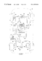
- FIG. 1 is a diagram of a vehicle including an electronic controller and associated input and output devices constituting a control system for carrying out an active brake control of vehicle yaw;
- FIG. 2 is a main flow diagram representative of computer instructions executed by the electronic controller of FIG. 1 in carrying out the control of this invention
- FIG. 3 is a flow diagram setting forth further detail regarding the yaw rate limiting step of FIG. 2;
- FIGS. 4 A- 4 D graphically depict the development of a dynamic yaw rate limit according to this invention for a steering maneuver on a low adhesion road surface.
- FIG. 1 depicts a mechanization of an active brake control according to this invention on a vehicle 10 .
- the vehicle 10 includes a brake system having a micro-processor based controller 68 for controlling the brakes 20 , 22 , 24 , 26 of the respective wheels 12 , 14 , 16 , 18 .
- the controller 68 receives various inputs, including wheel speed signals on lines 36 , 38 , 40 , 42 from respective wheel speed sensors 28 , 30 , 32 , 34 ; a steering wheel angle signal on line 62 from angle sensor 61 ; a yaw rate signal on line 81 from yaw rate sensor 80 , a brake pedal travel signal on line 84 from pedal travel sensor 82 ; a master cylinder pressure signal on line 96 from the pressure sensor 94 ; and a lateral acceleration signal on line 99 from lateral accelerometer 98 .
- the sensors 28 , 30 , 32 , 34 , 61 , 80 , 82 , 94 , 98 may be implemented with conventional devices in a manner known to those skilled in the art.
- the controller 68 modifies the normal braking of one or more wheel 12 , 14 , 16 , 18 via the respective actuators 52 , 54 , 56 , 58 in order to restore a desired overall operation of the vehicle.
- the controller 68 commands one or more of the respective actuator(s) 52 , 54 , 56 , 58 to modulate the brake force developed at the wheel(s) experiencing the condition.
- the controller 68 commands one or more of the respective actuator(s) 52 , 54 , 56 , 58 to develop brake force at the slipping wheel(s).
- the controller 68 commands one or more of the respective actuator(s) 52 , 54 , 56 , 58 to selectively increase or decrease the brake forces generated at the wheels 12 , 14 , 16 , 18 to produce a commanded yaw.
- the yaw control is limited to the front (driven) wheels 12 , 14 , allowing the controller to estimate the yaw rate based on the speed differential of the undriven rear wheels; an example of such a control is set forth in the U.S. patent application Ser. No. 09/080,372, assigned to the assignee of the present invention.
- Exemplary actuators for either mechanization are shown and described in detail in the U.S. Pat. No. 5,366,281, assigned to the assignee of the present invention, and incorporated herein by reference.
- FIG. 2 is a main flow diagram representative of computer program instructions executed by the controller 68 of FIG. 1 in carrying out a yaw rate control according to this invention.
- the block 100 designates a series of initialization instructions executed at the initiation of vehicle operation for appropriately setting the initial condition or state of the various terms and flags referred to below.
- the block 104 - 110 are executed to determine a closed-loop yaw rate control command.
- Block 104 determines a desired yaw value ⁇ des for the vehicle based on various inputs including the vehicle speed V x and the measured steering wheel angle ⁇ .
- ⁇ des may be determined according to the expression:
- ⁇ des V x ⁇ /( L+K u V x 2 ) (1)
- Block 106 concerns the determination and application of yaw rate limiting according to this invention, and is described below in reference to the flow diagram of FIG. 3 .
- the pre-limit desired yaw rate from equation (1) is referred to herein as the input desired yaw rate, or ⁇ des-in
- the limited desired yaw rate emanating from block 106 is referred to as the output desired yaw rate, or ⁇ des-out .
- Block 108 determines the yaw error ⁇ err based on the deviation of the measured or estimated yaw rate from the output desired yaw rate ⁇ des-out .
- Block 110 determines a yaw rate control command based on the yaw rate error and suitable gain factors. Then block 112 decides if active brake control is warranted based on predefined entry and exit conditions. Finally, block 114 carries out an algorithm for distributing braking forces between the left and right vehicle wheels, and block 116 applies corresponding brake control signals to the brake actuators 152 - 158 .
- Various brake distribution strategies may be utilized, exemplary strategies being disclosed in the U.S. Pat. Nos. 5,667,286 and 5,720,533, both of which are assigned to the assignee of the present invention.
- a preliminary yaw rate limit ⁇ plim is determined as a function of vehicle speed V x and a dynamic estimate ⁇ est of the lateral adhesion capability of the road surface.
- the adhesion estimate ⁇ est is determined as a function of the measured lateral acceleration, possibly in combination with a measure of the longitudinal acceleration.
- the polarity of the measured lateral acceleration a y is preserved to ensure proper filtering, and the limit ⁇ plim is filtered to form an adhesion-related limit ⁇ plim-f having a frequency response similar to that of the input desired yaw rate ⁇ des-in .
- the dynamic yaw rate limit is developed in two stages ( ⁇ lim1 and ⁇ lim2 ), with the second stage limit ⁇ lim2 becoming the output desired yaw rate ⁇ des-out .
- FIGS. 4 A- 4 D the first and second stage yaw rate limits ⁇ lim1 and ⁇ lim2 , along with the preliminary yaw rate limit ⁇ plim , and the input and output desired yaw rates ⁇ des-in and ⁇ des-out for a steering maneuver on a low adhesion road surface are graphically depicted in FIGS. 4 A- 4 D.
- the four graphs have the same scale, with the time points t 0 -t 8 dividing the horizontal axis into a series of eight time intervals, designated as T 1 -T 8 .
- T 1 -T 8 the time intervals T 1 -T 8 are omitted from FIGS. 4 B- 4 D.
- the block 120 is first executed to determine an estimate ⁇ est of the lateral adhesion capability of the road surface, based on sensed vehicle acceleration, according to the expression:
- ⁇ 0 is a adhesion coefficient offset value
- K is a gain factor.
- the terms ⁇ 0 and K may be calibrated to create an adhesion estimate ⁇ est that is somewhat higher than strictly indicated by the lateral acceleration a y so that the desired yaw rate is not unnecessarily limited by the control. If the system also includes a longitudinal accelerometer, ⁇ est may alternatively be determined according to the expression:
- ⁇ est ⁇ 0 +K ( a x 2 +a y 2 ) 1 ⁇ 2 (3)
- the blocks 122 - 126 are executed to determine the value of the preliminary yaw rate limit ⁇ plim . If the magnitude of the lateral acceleration a y is less than a minimum reference lateral acceleration a ymin , such as 0.1 g, the limit ⁇ plim is set equal to zero. Otherwise, the limit ⁇ plim is determined according to the expression:
- ⁇ plim [( ⁇ est /V x )+ ⁇ 0 ]*sgn( a y ) (4)
- ⁇ 0 is a yaw rate limit offset value.
- the yaw rate limit ⁇ plim is filtered at block 128 by a first-order low-pass filter to form the filtered limit ⁇ plim-f as follows:
- ⁇ plim-f ( k ) ⁇ plim-f ( k ⁇ 1 )+ FC*[ ⁇ plim ( k ) ⁇ plim-f ( k ⁇ 1)] (5)
- FC is a filter constant having a value of 0.02, for example, and the designations (k) and (k ⁇ 1) refer to the current and previous control loop values, respectively, of the terms ⁇ plim and ⁇ plim-f .
- the preliminary yaw rate limit ⁇ plim-f becomes substantially out of phase with the input desired yaw rate ⁇ des-in during a steering maneuver, particularly on a low adhesion surface such as snow.
- the first and second stage limits ⁇ lim1 and ⁇ lim2 are developed based on the relative magnitudes of ⁇ des-in and ⁇ plim-f to form a dynamic yaw rate limit that is in-phase with the desired yaw rate ⁇ des-in , and retains the adhesion capability information contained in the preliminary yaw rate limit ⁇ plim-f .
- the second stage limit ⁇ lim2 becomes the output desired yaw rate ⁇ des-out , which as described above in reference to FIG. 2, is combined with the actual or estimated yaw rate to form the yaw rate error ⁇ err .
- the block 130 determines if active brake control (ABC) is active. If not, the blocks 132 and 134 are executed to set the first and second stage yaw rate limits ⁇ lim1 and ⁇ lim2 as well as the output desired yaw rate ⁇ des-out equal to the input desired yaw rate ⁇ des-in . If ABC is active, blocks 136 - 140 set the first limit term ⁇ lim1 equal to the lesser in magnitude of the input desired yaw rate ⁇ des-in and the filtered preliminary yaw rate limit ⁇ plim-f .
- ABS active brake control
- the SGN function of block 138 preserves the polarity of the input desired yaw rate ⁇ des-in when ⁇ lim1 is determined according to ⁇ plim-f , thereby ensuring that ⁇ lim1 is in phase with ⁇ des-in .
- the limit ⁇ lim1 is depicted by the solid trace of FIG. 4 B. As seen in the graph, limit ⁇ lim1 deviates from the input desired yaw rate ⁇ des-in during the time intervals T 3 , T 5 and T 7 .
- the purpose of the second stage limit ⁇ lim2 is to modify the first stage limit ⁇ lim1 in a manner to retain both the magnitude information of ⁇ plim-f and the phase information of ⁇ des-in . This is accomplished by tracking the peak value of ⁇ lim1 within the envelope or boundary of the input desired yaw rate ⁇ des-in . This is graphically depicted in FIG. 4C, where the second stage limit ⁇ lim2 is shown by the solid trace, and the broken trace shows the omitted excursions of the first stage limit ⁇ lim1 .
- the second stage limit ⁇ lim2 becomes the output desired yaw rate ⁇ des-out , and is shown in FIG.
- the block 142 compares the magnitude of the input desired yaw rate ⁇ des-in to the magnitude of the previous (last) value of the second limit term ⁇ lim2 (last). If
- blocks 134 and 152 - 154 apply the second limit term ⁇ lim2 to the input desired yaw rate ⁇ des-in to form the output desired yaw rate ⁇ des-out .
- the output desired yaw rate ⁇ des-out is set equal to the lesser of the input desired yaw rate ⁇ des-in and the second limit term ⁇ lim2 .
- the output desired yaw rate ⁇ des-out is then used in combination with the measured or estimated yaw rate to determine the yaw rate error, and the yaw rate control command.
- control of this invention dynamically limits the desired yaw rate based on a limit derived from the measured lateral acceleration of the vehicle during a steering maneuver. This in turn limits the yaw rate control command so as to tailor the yaw control in accordance with the adhesion capability of the road surface.
Landscapes
- Engineering & Computer Science (AREA)
- Transportation (AREA)
- Mechanical Engineering (AREA)
- Regulating Braking Force (AREA)
Abstract
An improved closed-loop vehicle yaw control in which a yaw rate limit based on measured lateral acceleration is used during transient steering maneuvers to dynamically limit a desired yaw rate derived from driver steering input. A preliminary yaw rate limit is computed based on the measured lateral acceleration, and a dynamic yaw rate limit having a proper phase relationship with the desired yaw rate is developed based on the relative magnitudes of the desired yaw rate and the preliminary yaw rate limit. A two-stage process is used to develop the dynamic yaw rate limit. A first stage yaw rate limit is determined according the lower in magnitude of the desired yaw rate and the preliminary yaw rate limit, and a second stage yaw rate limit (i.e., the dynamic yaw rate limit) is determined according to the relative magnitudes of (1) the desired yaw rate and the second stage yaw rate limit, and (2) the first stage yaw rate limit and the second stage yaw rate limit. The desired yaw rate, as limited by the dynamic yaw rate limit, is then combined with the actual or estimated yaw rate to form a yaw rate error, which in turn, is used to develop a yaw rate control command for the vehicle.
Description
This invention relates to a vehicle yaw rate control, and more particularly to a method for limiting the yaw rate command consistent with the lateral adhesion capability of the road surface.
In general, vehicle yaw rate control systems determine a desired yaw rate based on driver steering angle and other parameters, develop a yaw rate control command, and selectively brake one or more vehicle wheels in accordance with the yaw rate control command so that the vehicle achieves the desired yaw rate. In open-loop systems, the yaw rate control command is determined primarily as a function of the desired yaw rate, whereas in closed-loop systems, the yaw rate control command is determined primarily as a function of the difference, or error, between the desired yaw rate and a measure or estimate of the actual yaw rate. In either type of system, the determination of the desired yaw rate is based on an assumption that the vehicle is operating on dry pavement—that is, a surface having a high lateral coefficient of adhesion. Thus if the surface adhesion capability is not taken into account, the desired yaw rate can easily exceed the surface adhesion capability when the vehicle is operating on a slippery surface such as snow. In such circumstances, the yaw rate control will not be optimal.
Two different approaches for addressing reduction in surface adhesion capability have been considered. The simplest approach is to reduce the control gains, but this also reduces the overall aggressiveness of the control, and is often not favored. The second approach is to estimate the surface adhesion capability during a steering maneuver based on a measure of instantaneous lateral acceleration, and to dynamically limit the desired yaw rate accordingly. While this approach works well when the steering input is substantially constant, it does not work well during transient steering because the desired yaw rate and the lateral acceleration (and therefore, the surface adhesion estimate) are not in phase with each other. This phenomenon can be seen in the graph of FIG. 4A, which depicts a yaw rate limit based on lateral acceleration (solid trace) with the desired yaw rate (broken trace) during a transient steering maneuver on a low adhesion surface. As soon as the steering begins to change significantly, the desired yaw rate begins to lead the yaw rate limit, to the point of being completely out of phase. Accordingly, the robustness of the second approach is limited.
The present invention is directed to an improved closed-loop vehicle yaw control in which a yaw rate limit based on measured lateral acceleration is used during transient steering maneuvers to dynamically limit a desired yaw rate derived from driver steering input. According to the invention, a preliminary yaw rate limit is computed based on the measured lateral acceleration, and a dynamic yaw rate limit having a proper phase relationship with the desired yaw rate is developed based on the relative magnitudes of the desired yaw rate and the preliminary yaw rate limit. In the preferred embodiment, a two-stage process is used to develop the dynamic yaw rate limit. A first stage yaw rate limit is determined according the lower in magnitude of the desired yaw rate and the preliminary yaw rate limit, and a second stage yaw rate limit (i.e., the dynamic yaw rate limit) is determined according to the relative magnitudes of (1) the desired yaw rate and the second stage yaw rate limit, and (2) the first stage yaw rate limit and the second stage yaw rate limit. The desired yaw rate, as limited by the dynamic yaw rate limit, is then combined with the actual or estimated yaw rate to form a yaw rate error, which in turn, is used to develop a yaw rate command for the vehicle.
The present invention will now be described, by way of example, with reference to the accompanying drawings, in which:
FIG. 1 is a diagram of a vehicle including an electronic controller and associated input and output devices constituting a control system for carrying out an active brake control of vehicle yaw;
FIG. 2 is a main flow diagram representative of computer instructions executed by the electronic controller of FIG. 1 in carrying out the control of this invention;
FIG. 3 is a flow diagram setting forth further detail regarding the yaw rate limiting step of FIG. 2; and
FIGS. 4A-4D graphically depict the development of a dynamic yaw rate limit according to this invention for a steering maneuver on a low adhesion road surface.
FIG. 1 depicts a mechanization of an active brake control according to this invention on a vehicle 10. The vehicle 10 includes a brake system having a micro-processor based controller 68 for controlling the brakes 20, 22, 24, 26 of the respective wheels 12, 14, 16, 18. The controller 68 receives various inputs, including wheel speed signals on lines 36, 38, 40, 42 from respective wheel speed sensors 28, 30, 32, 34; a steering wheel angle signal on line 62 from angle sensor 61; a yaw rate signal on line 81 from yaw rate sensor 80, a brake pedal travel signal on line 84 from pedal travel sensor 82; a master cylinder pressure signal on line 96 from the pressure sensor 94; and a lateral acceleration signal on line 99 from lateral accelerometer 98. The sensors 28, 30, 32, 34, 61, 80, 82, 94, 98 may be implemented with conventional devices in a manner known to those skilled in the art.
Under certain conditions such as wheel lock-up or spinning, or lateral instability, the controller 68 modifies the normal braking of one or more wheel 12, 14, 16, 18 via the respective actuators 52, 54, 56, 58 in order to restore a desired overall operation of the vehicle. In an incipient lock-up condition, the controller 68 commands one or more of the respective actuator(s) 52, 54, 56, 58 to modulate the brake force developed at the wheel(s) experiencing the condition. In a wheel slip condition, the controller 68 commands one or more of the respective actuator(s) 52, 54, 56, 58 to develop brake force at the slipping wheel(s). In a case of lateral instability, the controller 68 commands one or more of the respective actuator(s) 52, 54, 56, 58 to selectively increase or decrease the brake forces generated at the wheels 12, 14, 16, 18 to produce a commanded yaw. In certain applications, the yaw control is limited to the front (driven) wheels 12, 14, allowing the controller to estimate the yaw rate based on the speed differential of the undriven rear wheels; an example of such a control is set forth in the U.S. patent application Ser. No. 09/080,372, assigned to the assignee of the present invention. Exemplary actuators for either mechanization are shown and described in detail in the U.S. Pat. No. 5,366,281, assigned to the assignee of the present invention, and incorporated herein by reference.
FIG. 2 is a main flow diagram representative of computer program instructions executed by the controller 68 of FIG. 1 in carrying out a yaw rate control according to this invention. The block 100 designates a series of initialization instructions executed at the initiation of vehicle operation for appropriately setting the initial condition or state of the various terms and flags referred to below. After reading the various sensor inputs at block 102, the block 104-110 are executed to determine a closed-loop yaw rate control command. Block 104 determines a desired yaw value Ωdes for the vehicle based on various inputs including the vehicle speed Vx and the measured steering wheel angle δ. For example, Ωdes may be determined according to the expression:
where L is wheel base of the vehicle, and Ku is an understeer coefficient. Block 106 concerns the determination and application of yaw rate limiting according to this invention, and is described below in reference to the flow diagram of FIG. 3. For convenience, the pre-limit desired yaw rate from equation (1) is referred to herein as the input desired yaw rate, or Ωdes-in, whereas the limited desired yaw rate emanating from block 106 is referred to as the output desired yaw rate, or Ωdes-out. Block 108 determines the yaw error Ωerr based on the deviation of the measured or estimated yaw rate from the output desired yaw rate Ωdes-out. Block 110 then determines a yaw rate control command based on the yaw rate error and suitable gain factors. Then block 112 decides if active brake control is warranted based on predefined entry and exit conditions. Finally, block 114 carries out an algorithm for distributing braking forces between the left and right vehicle wheels, and block 116 applies corresponding brake control signals to the brake actuators 152-158. Various brake distribution strategies may be utilized, exemplary strategies being disclosed in the U.S. Pat. Nos. 5,667,286 and 5,720,533, both of which are assigned to the assignee of the present invention.
As indicated above, the flow diagram of FIG. 3 details the development and application of a dynamic yaw rate limit according to this invention. In general, a preliminary yaw rate limit Ωplim is determined as a function of vehicle speed Vx and a dynamic estimate μest of the lateral adhesion capability of the road surface. The adhesion estimate μest, in turn, is determined as a function of the measured lateral acceleration, possibly in combination with a measure of the longitudinal acceleration. In forming the preliminary yaw rate limit Ωplim, the polarity of the measured lateral acceleration ay is preserved to ensure proper filtering, and the limit Ωplim is filtered to form an adhesion-related limit Ωplim-f having a frequency response similar to that of the input desired yaw rate Ωdes-in. The dynamic yaw rate limit is developed in two stages (Ωlim1 and Ωlim2), with the second stage limit Ωlim2 becoming the output desired yaw rate Ωdes-out.
To aid in the description of FIG. 3, the first and second stage yaw rate limits Ωlim1 and Ωlim2, along with the preliminary yaw rate limit Ωplim, and the input and output desired yaw rates Ωdes-in and Ωdes-out for a steering maneuver on a low adhesion road surface are graphically depicted in FIGS. 4A-4D. The four graphs have the same scale, with the time points t0-t8 dividing the horizontal axis into a series of eight time intervals, designated as T1-T8. For convenience, the time intervals T1-T8 are omitted from FIGS. 4B-4D.
Referring to FIG. 3, the block 120 is first executed to determine an estimate μest of the lateral adhesion capability of the road surface, based on sensed vehicle acceleration, according to the expression:
where μ0 is a adhesion coefficient offset value, and K is a gain factor. The terms μ0 and K may be calibrated to create an adhesion estimate μest that is somewhat higher than strictly indicated by the lateral acceleration ay so that the desired yaw rate is not unnecessarily limited by the control. If the system also includes a longitudinal accelerometer, μest may alternatively be determined according to the expression:
where (ax 2+ay 2)½ is the resultant vector of the lateral acceleration ay and the longitudinal acceleration ax.
Once the adhesion estimate pest is determined, the blocks 122-126 are executed to determine the value of the preliminary yaw rate limit Ωplim. If the magnitude of the lateral acceleration ay is less than a minimum reference lateral acceleration aymin, such as 0.1 g, the limit Ωplim is set equal to zero. Otherwise, the limit Ωplim is determined according to the expression:
Ωplim=[(μest /V x)+Ω0]*sgn(a y) (4)
where Ω0is a yaw rate limit offset value. Thereafter, the yaw rate limit Ωplim is filtered at block 128 by a first-order low-pass filter to form the filtered limit Ωplim-f as follows:
where FC is a filter constant having a value of 0.02, for example, and the designations (k) and (k−1) refer to the current and previous control loop values, respectively, of the terms Ωplim and Ωplim-f.
As indicated above, and as seen in FIG. 4A, the preliminary yaw rate limit Ωplim-f becomes substantially out of phase with the input desired yaw rate Ωdes-in during a steering maneuver, particularly on a low adhesion surface such as snow. As explained below, the first and second stage limits Ωlim1 and Ωlim2 are developed based on the relative magnitudes of Ωdes-in and Ωplim-f to form a dynamic yaw rate limit that is in-phase with the desired yaw rate Ωdes-in, and retains the adhesion capability information contained in the preliminary yaw rate limit Ωplim-f. In the illustrated embodiment, the second stage limit Ωlim2 becomes the output desired yaw rate Ωdes-out, which as described above in reference to FIG. 2, is combined with the actual or estimated yaw rate to form the yaw rate error Ωerr.
Referring to FIG. 3, the block 130 determines if active brake control (ABC) is active. If not, the blocks 132 and 134 are executed to set the first and second stage yaw rate limits Ωlim1 and Ωlim2 as well as the output desired yaw rate Ωdes-out equal to the input desired yaw rate Ωdes-in. If ABC is active, blocks 136-140 set the first limit term Ωlim1 equal to the lesser in magnitude of the input desired yaw rate Ωdes-in and the filtered preliminary yaw rate limit Ωplim-f. Significantly, the SGN function of block 138 preserves the polarity of the input desired yaw rate Ωdes-in when Ωlim1 is determined according to Ωplim-f, thereby ensuring that Ωlim1 is in phase with Ωdes-in. In the exemplary steering maneuver of FIG. 4, the limit Ωlim1 is depicted by the solid trace of FIG. 4B. As seen in the graph, limit Ωlim1 deviates from the input desired yaw rate Ωdes-in during the time intervals T3, T5 and T7. However, it is also seen that in such time intervals, the magnitude information of Ωplim-f is not correctly represented due to the out-of-phase relationship of Ωplim-f and Ωdes-in. In fact, there are several instances where Ωplim-f and Ωdes-in are changing in opposite directions; see, for example, the first part of time interval T3 (t2-t2a), the entire time interval T5, and the last part of time interval T7 (t6a-t7).
Accordingly, the purpose of the second stage limit Ωlim2 is to modify the first stage limit Ωlim1 in a manner to retain both the magnitude information of Ωplim-f and the phase information of Ωdes-in. This is accomplished by tracking the peak value of Ωlim1 within the envelope or boundary of the input desired yaw rate Ωdes-in. This is graphically depicted in FIG. 4C, where the second stage limit Ωlim2 is shown by the solid trace, and the broken trace shows the omitted excursions of the first stage limit Ωlim1. The second stage limit Ωlim2 becomes the output desired yaw rate Ωdes-out, and is shown in FIG. 4D (solid trace) along with the input desired yaw rate Ωdes-in (broken trace). Thus, it can be seen that the input desired yaw rate Ωdes-in is dynamically limited based on the road surface capability information contained in the preliminary yaw rate limit Ωplim-f.
Referring to FIG. 3, the block 142 compares the magnitude of the input desired yaw rate Ωdes-in to the magnitude of the previous (last) value of the second limit term Ωlim2(last). If |Ωdes-in| is less than or equal to |Ωlim2(last)|, the driver is commanding a yaw rate within the previously determined surface capability, and block 144 is executed to set Ωlim2 equal to Ωdes-in. Examples of this occur in the latter parts of time intervals T5 and T7. However, if |Ωdes-in| is greater than |Ωlim2 1(last)|, the driver is commanding a yaw rate larger than the previously determined surface capability, and block 146 is executed to determine if the magnitude of Ωlim1 is greater than the magnitude of Ωlim2(last). If not, the block 150 holds the previous value of the second stage limit Ωlim2. Examples of this occur in the first parts of time intervals T3, T5 and T7. If |Ωlim1| is greater than |Ωlim2(last)|, the block 148 sets the second stage limit Ωlim2 equal to the first stage limit Ωlim1 to reflect the higher limit value. An example of this occurs in the latter part of time interval T3.
Finally, blocks 134 and 152-154 apply the second limit term Ωlim2 to the input desired yaw rate Ωdes-in to form the output desired yaw rate Ωdes-out. In other words, the output desired yaw rate Ωdes-out is set equal to the lesser of the input desired yaw rate Ωdes-in and the second limit term Ωlim2. As described above, the output desired yaw rate Ωdes-out is then used in combination with the measured or estimated yaw rate to determine the yaw rate error, and the yaw rate control command.
In summary, the control of this invention dynamically limits the desired yaw rate based on a limit derived from the measured lateral acceleration of the vehicle during a steering maneuver. This in turn limits the yaw rate control command so as to tailor the yaw control in accordance with the adhesion capability of the road surface. As indicated above, it is expected that various modifications of the illustrated embodiment will occur to those skilled in the art, and in this regard, it will be understood that the scope of this invention is not necessarily limited by the illustrated embodiment, but instead is defined by the appended claims.
Claims (8)
1. A limited yaw rate control method in which vehicle wheels are differentially braked in response to a yaw command based on a deviation of a vehicle yaw rate from a desired yaw rate, the improvement comprising the steps of:
measuring a lateral acceleration of the vehicle;
developing a preliminary yaw rate limit based on the measured lateral acceleration;
forming a first stage yaw rate limit according to the lesser in magnitude of the desired yaw rate and the preliminary yaw rate limit, while preserving the polarity of the desired yaw rate;
forming a second stage yaw rate limit according to a peak excursion of the first stage yaw rate limit; and
limiting the desired yaw rate according to the lesser in magnitude of the second stage yaw rate limit and the desired yaw rate.
2. The improvement of claim 1, wherein the peak excursion of the first stage yaw rate limit is identified by detecting a reduction in magnitude of said first stage yaw rate limit within an envelope defined by the desired yaw rate.
3. The improvement of claim 1, including the steps of:
preserving the polarity of the measured lateral acceleration in developing said preliminary yaw rate limit; and
filtering said preliminary yaw rate limit so that said preliminary yaw rate limit has a frequency response similar to a frequency response of said desired yaw rate.
4. The improvement of claim 1, including the step of:
setting said first and second stage yaw rate limits equal to said desired yaw rate when said yaw rate control is deactivated.
5. A limited yaw rate control method in which vehicle wheels are differentially braked in response to a yaw command based on a deviation of a vehicle yaw rate from a desired yaw rate, the improvement comprising the steps of:
measuring a lateral acceleration of the vehicle;
developing a preliminary yaw rate limit based on the measured lateral acceleration;
forming a first stage yaw rate limit according to the lesser in magnitude of the desired yaw rate and the preliminary yaw rate limit, while preserving the polarity of the desired yaw rate;
forming a second stage yaw rate limit according to the greater in magnitude of the first stage yaw rate limit and a previous value of said second stage yaw rate limit; and
limiting the desired yaw rate according to the lesser in magnitude of the second stage yaw rate limit and the desired yaw rate.
6. The improvement of claim 5, wherein the peak excursion of the first stage yaw rate limit is identified by detecting a reduction in magnitude of said first stage yaw rate limit within an envelope defined by the desired yaw rate.
7. The improvement of claim 5, including the steps of:
preserving the polarity of the measured lateral acceleration in developing said preliminary yaw rate limit; and
filtering said preliminary yaw rate limit so that said preliminary yaw rate limit has a frequency response similar to a frequency response of said desired yaw rate.
8. The improvement of claim 5, including the step of:
setting said first and second stage yaw rate limits equal to said desired yaw rate when said yaw rate control is deactivated.
Priority Applications (1)
| Application Number | Priority Date | Filing Date | Title |
|---|---|---|---|
| US09/138,737 US6175790B1 (en) | 1998-08-24 | 1998-08-24 | Vehicle yaw rate control with yaw rate command limiting |
Applications Claiming Priority (1)
| Application Number | Priority Date | Filing Date | Title |
|---|---|---|---|
| US09/138,737 US6175790B1 (en) | 1998-08-24 | 1998-08-24 | Vehicle yaw rate control with yaw rate command limiting |
Publications (1)
| Publication Number | Publication Date |
|---|---|
| US6175790B1 true US6175790B1 (en) | 2001-01-16 |
Family
ID=22483402
Family Applications (1)
| Application Number | Title | Priority Date | Filing Date |
|---|---|---|---|
| US09/138,737 Expired - Fee Related US6175790B1 (en) | 1998-08-24 | 1998-08-24 | Vehicle yaw rate control with yaw rate command limiting |
Country Status (1)
| Country | Link |
|---|---|
| US (1) | US6175790B1 (en) |
Cited By (16)
| Publication number | Priority date | Publication date | Assignee | Title |
|---|---|---|---|---|
| EP1201519A1 (en) * | 2000-10-24 | 2002-05-02 | Mazda Motor Corporation | Vehicle posture control apparatus |
| US6494281B1 (en) * | 1998-04-07 | 2002-12-17 | Robert Bosch Gmbh | Method and device for stabilizing a vehicle |
| US6560524B2 (en) | 2001-09-26 | 2003-05-06 | General Motors Corporation | Integration of rear wheel steering with vehicle stability enhancement system |
| US6625527B1 (en) * | 1999-02-18 | 2003-09-23 | Continental Teves Ag & Co. Ohg | Sensor system with monitoring device |
| US20040102887A1 (en) * | 2002-11-26 | 2004-05-27 | Lin William C. | Method and apparatus for vehicle stability enhancement system |
| US20040133326A1 (en) * | 2003-01-03 | 2004-07-08 | Ghoneim Youssef Ahmed | Method and apparatus for vehicle integrated chassis control system |
| US20040133321A1 (en) * | 2003-01-03 | 2004-07-08 | Ghoneim Youssef Ahmed | Method and apparatus for vehicle stability enhancement system |
| US20040201272A1 (en) * | 2003-04-08 | 2004-10-14 | Delphi Technologies Inc. | ABS yaw control with yaw rate sensor |
| US6813552B2 (en) | 2002-11-18 | 2004-11-02 | General Motors Corporation | Method and apparatus for vehicle stability enhancement system |
| US6865468B2 (en) | 2002-11-26 | 2005-03-08 | General Motors Corporation | Method and apparatus for vehicle stability enhancement system |
| US6879896B2 (en) | 2002-04-11 | 2005-04-12 | Delphi Technologies, Inc. | System and method for using vehicle operator intent to adjust vehicle control system response |
| WO2005063537A1 (en) * | 2003-12-23 | 2005-07-14 | Daimlerchrysler Ag | Device and method for reducing roll in a vehicle |
| US20080208406A1 (en) * | 2007-02-28 | 2008-08-28 | Gm Global Technology Operations, Inc. | Nonlinear vehicle yaw/roll/sideslip command interpreter |
| US20090112434A1 (en) * | 2007-10-29 | 2009-04-30 | Mando Corporation | Electronic hydraulic pressure control system and control method thereof |
| US9248833B2 (en) | 2012-06-21 | 2016-02-02 | Eaton Corporation | Predictive vehicle stability control method |
| US20220250678A1 (en) * | 2021-02-08 | 2022-08-11 | Continental Automotive Gmbh | Regulating device and method for regulating the steering angle of a vehicle |
Citations (23)
| Publication number | Priority date | Publication date | Assignee | Title |
|---|---|---|---|---|
| US4834205A (en) | 1987-02-03 | 1989-05-30 | Kabushiki Kaisha Toyota Chuo Kenkyusho | Apparatus for controlling steering of wheels of a vehicle |
| US5063514A (en) | 1990-06-19 | 1991-11-05 | General Motors Corporation | Abs yaw control |
| DE4123235C1 (en) | 1991-07-13 | 1992-11-26 | Daimler Benz Ag | |
| US5172961A (en) | 1990-07-05 | 1992-12-22 | Nissan Motor Co. Ltd. | Vehicle brake system including cornering characteristic control |
| DE4121954A1 (en) | 1991-07-03 | 1993-01-07 | Bosch Gmbh Robert | METHOD FOR OBTAINING THE YEAR SPEED AND / OR THE LATERAL SPEED |
| DE4200061A1 (en) | 1992-01-03 | 1993-07-08 | Bosch Gmbh Robert | METHOD FOR DETERMINING THE VEHICLE CROSS SPEED AND / OR THE SWIMMING ANGLE |
| US5229944A (en) | 1990-03-22 | 1993-07-20 | Yoshiki Yasuno | Braking force control apparatus |
| GB2263340A (en) | 1992-01-16 | 1993-07-21 | Steyr Daimler Puch Ag | Method for determining the dynamic safety margin of motor vehicles |
| EP0555860A1 (en) | 1992-02-14 | 1993-08-18 | Honda Giken Kogyo Kabushiki Kaisha | Steering stability control system for vehicle |
| US5275475A (en) | 1990-08-23 | 1994-01-04 | Robert Bosch Gmbh | Method for controlling vehicle dynamics |
| DE4223385A1 (en) | 1992-07-16 | 1994-01-20 | Bosch Gmbh Robert | Detecting reverse motion of motor vehicle for brake control system - measuring yaw rate, vehicle speed, wheel state and steering angle and using given equations to derive forward or reverse motion signals |
| GB2269571A (en) | 1992-08-13 | 1994-02-16 | Daimler Benz Ag | Process for determining quantities characterising vehicle travel behaviour. |
| DE4229504A1 (en) | 1992-09-04 | 1994-03-10 | Bosch Gmbh Robert | Vehicle road-curve stability regulation procedure - involves regulation of actual yaw velocity by comparison with required value as calculated from detected parameters |
| GB2275312A (en) | 1993-02-19 | 1994-08-24 | Bosch Gmbh Robert | Vehicle movement dynamics control system |
| GB2275551A (en) | 1991-10-21 | 1994-08-31 | Intel Corp | Cross coupling mechanisms for microprocessor instructions using pipelining systems. |
| DE4311077A1 (en) | 1993-04-03 | 1994-10-06 | Bosch Gmbh Robert | Anti-lock control system |
| DE4314827A1 (en) | 1993-05-05 | 1994-11-10 | Porsche Ag | Method for determining the yaw velocity of a vehicle |
| US5366281A (en) | 1994-02-14 | 1994-11-22 | General Motors Corporation | Method of initializing a brake actuator |
| US5444621A (en) | 1991-06-10 | 1995-08-22 | Nippondenso Co., Ltd. | Suspension control system for controlling suspension of automotive vehicle based on wheel speed data |
| US5480219A (en) | 1992-12-23 | 1996-01-02 | Robert Bosch Gmbh | Control of vehicle side slip using yaw rate |
| US5667286A (en) * | 1996-05-29 | 1997-09-16 | General Motors Corporation | Brake control system |
| US5720533A (en) | 1996-10-15 | 1998-02-24 | General Motors Corporation | Brake control system |
| US5746486A (en) | 1996-10-16 | 1998-05-05 | General Motors Corporation | Brake control system |
-
1998
- 1998-08-24 US US09/138,737 patent/US6175790B1/en not_active Expired - Fee Related
Patent Citations (26)
| Publication number | Priority date | Publication date | Assignee | Title |
|---|---|---|---|---|
| US4834205A (en) | 1987-02-03 | 1989-05-30 | Kabushiki Kaisha Toyota Chuo Kenkyusho | Apparatus for controlling steering of wheels of a vehicle |
| US5229944A (en) | 1990-03-22 | 1993-07-20 | Yoshiki Yasuno | Braking force control apparatus |
| US5063514A (en) | 1990-06-19 | 1991-11-05 | General Motors Corporation | Abs yaw control |
| US5172961A (en) | 1990-07-05 | 1992-12-22 | Nissan Motor Co. Ltd. | Vehicle brake system including cornering characteristic control |
| US5275475A (en) | 1990-08-23 | 1994-01-04 | Robert Bosch Gmbh | Method for controlling vehicle dynamics |
| US5444621A (en) | 1991-06-10 | 1995-08-22 | Nippondenso Co., Ltd. | Suspension control system for controlling suspension of automotive vehicle based on wheel speed data |
| DE4121954A1 (en) | 1991-07-03 | 1993-01-07 | Bosch Gmbh Robert | METHOD FOR OBTAINING THE YEAR SPEED AND / OR THE LATERAL SPEED |
| US5311431A (en) | 1991-07-03 | 1994-05-10 | Robert Bosch Gmbh | Method of obtaining the yawing velocity and/or transverse velocity of a vehicle |
| US5341297A (en) | 1991-07-13 | 1994-08-23 | Mercedes-Benz Ag | Apparatus and method for preventing instabilities in vehicle handling |
| DE4123235C1 (en) | 1991-07-13 | 1992-11-26 | Daimler Benz Ag | |
| GB2275551A (en) | 1991-10-21 | 1994-08-31 | Intel Corp | Cross coupling mechanisms for microprocessor instructions using pipelining systems. |
| DE4200061A1 (en) | 1992-01-03 | 1993-07-08 | Bosch Gmbh Robert | METHOD FOR DETERMINING THE VEHICLE CROSS SPEED AND / OR THE SWIMMING ANGLE |
| GB2263340A (en) | 1992-01-16 | 1993-07-21 | Steyr Daimler Puch Ag | Method for determining the dynamic safety margin of motor vehicles |
| EP0555860A1 (en) | 1992-02-14 | 1993-08-18 | Honda Giken Kogyo Kabushiki Kaisha | Steering stability control system for vehicle |
| DE4223385A1 (en) | 1992-07-16 | 1994-01-20 | Bosch Gmbh Robert | Detecting reverse motion of motor vehicle for brake control system - measuring yaw rate, vehicle speed, wheel state and steering angle and using given equations to derive forward or reverse motion signals |
| GB2269571A (en) | 1992-08-13 | 1994-02-16 | Daimler Benz Ag | Process for determining quantities characterising vehicle travel behaviour. |
| DE4229504A1 (en) | 1992-09-04 | 1994-03-10 | Bosch Gmbh Robert | Vehicle road-curve stability regulation procedure - involves regulation of actual yaw velocity by comparison with required value as calculated from detected parameters |
| US5402342A (en) | 1992-09-04 | 1995-03-28 | Robert Bosch Gmbh | Method for controlling motor vehicle stability |
| US5480219A (en) | 1992-12-23 | 1996-01-02 | Robert Bosch Gmbh | Control of vehicle side slip using yaw rate |
| GB2275312A (en) | 1993-02-19 | 1994-08-24 | Bosch Gmbh Robert | Vehicle movement dynamics control system |
| DE4311077A1 (en) | 1993-04-03 | 1994-10-06 | Bosch Gmbh Robert | Anti-lock control system |
| DE4314827A1 (en) | 1993-05-05 | 1994-11-10 | Porsche Ag | Method for determining the yaw velocity of a vehicle |
| US5366281A (en) | 1994-02-14 | 1994-11-22 | General Motors Corporation | Method of initializing a brake actuator |
| US5667286A (en) * | 1996-05-29 | 1997-09-16 | General Motors Corporation | Brake control system |
| US5720533A (en) | 1996-10-15 | 1998-02-24 | General Motors Corporation | Brake control system |
| US5746486A (en) | 1996-10-16 | 1998-05-05 | General Motors Corporation | Brake control system |
Non-Patent Citations (16)
| Title |
|---|
| Active Stability Control; Junichi Kubokawa, Aisin Seiki Co., Ltd., Electronics & Brake Division; Abstract; Sep. 1995. |
| Consideration of Lateral and longitudinal Vehicle Stability by Function Enhanced Brake and Stability Control System; Heinz Leffler; SAE #940832; Feb. 28-Mar. 3, 1994. |
| Control of Vehicle Dynamics: Automotive Engineering; pp. 87-93; May 1995. |
| Controlling Vehicle Stability; Christopher A. Sawyer, Automotive Industries, Jan. 1995. |
| Handling Control Systems For Your Car: Popular Electronics; Feb. 1995, pp. 37-39, 93. |
| Improvement of Vehicle Maneuverability by Direct Yaw Moment Control; Y. Shibahata, K. Shimada and T. Tomari; Society of Automotive Engineers of Japan, Inc.; pp. 464-481. |
| Let Magic Fingers Do The Driving: Wards Auto World; May 1995. |
| May The Cornering Force Be With You; Popular Mechanics; Dec. 1995, pp. 74-77. |
| Mercedes/Bosch ESP; Automotive Industries, Apr. 1995. |
| Spin Control For Cars; Steven Ashley; Mechanical Engineering; pp. 66-68; Jun. 1995. |
| Stable As She Goes; Don Sherman, Automotive Industries, May 1995. |
| Technoid: Intelligent Brakes Are On The Way; Car and Driver, Aug. 1994. |
| The Spin Doctors: Don Sherman, Popular Science, Dec. 1995. |
| Toyota Vehicle Stability Control System; Automotive Engineering, Aug. 1995. |
| VDC, The Vehicle Dynamics Control System of Bosch: A. VanZanten, R. Erhardt and G. Pfaff; Robert Bosch GmbH; No. 950759, pp. 9-26. |
| Vehicle Dynamics Offers New Level Of Safety: Machine Design, Sep. 1994, p. 52. |
Cited By (24)
| Publication number | Priority date | Publication date | Assignee | Title |
|---|---|---|---|---|
| US6494281B1 (en) * | 1998-04-07 | 2002-12-17 | Robert Bosch Gmbh | Method and device for stabilizing a vehicle |
| US6625527B1 (en) * | 1999-02-18 | 2003-09-23 | Continental Teves Ag & Co. Ohg | Sensor system with monitoring device |
| US6622073B2 (en) | 2000-10-24 | 2003-09-16 | Mazda Motor Corporation | Vehicle posture control apparatus |
| EP1201519A1 (en) * | 2000-10-24 | 2002-05-02 | Mazda Motor Corporation | Vehicle posture control apparatus |
| US6560524B2 (en) | 2001-09-26 | 2003-05-06 | General Motors Corporation | Integration of rear wheel steering with vehicle stability enhancement system |
| US6879896B2 (en) | 2002-04-11 | 2005-04-12 | Delphi Technologies, Inc. | System and method for using vehicle operator intent to adjust vehicle control system response |
| US6813552B2 (en) | 2002-11-18 | 2004-11-02 | General Motors Corporation | Method and apparatus for vehicle stability enhancement system |
| US6819998B2 (en) | 2002-11-26 | 2004-11-16 | General Motors Corporation | Method and apparatus for vehicle stability enhancement system |
| US20040102887A1 (en) * | 2002-11-26 | 2004-05-27 | Lin William C. | Method and apparatus for vehicle stability enhancement system |
| US6865468B2 (en) | 2002-11-26 | 2005-03-08 | General Motors Corporation | Method and apparatus for vehicle stability enhancement system |
| US6879898B2 (en) | 2003-01-03 | 2005-04-12 | General Motors Corporation | Method and apparatus for vehicle integrated chassis control system |
| US20040133321A1 (en) * | 2003-01-03 | 2004-07-08 | Ghoneim Youssef Ahmed | Method and apparatus for vehicle stability enhancement system |
| US20040133326A1 (en) * | 2003-01-03 | 2004-07-08 | Ghoneim Youssef Ahmed | Method and apparatus for vehicle integrated chassis control system |
| US6968261B2 (en) | 2003-01-03 | 2005-11-22 | General Motors Corporation | Method and apparatus for vehicle stability enhancement system |
| US20040201272A1 (en) * | 2003-04-08 | 2004-10-14 | Delphi Technologies Inc. | ABS yaw control with yaw rate sensor |
| WO2005063537A1 (en) * | 2003-12-23 | 2005-07-14 | Daimlerchrysler Ag | Device and method for reducing roll in a vehicle |
| US20070213900A1 (en) * | 2003-12-23 | 2007-09-13 | Daimlerchrysler Ag | Method and Apparatus for Preventing Rollover of a Vehicle |
| US20080208406A1 (en) * | 2007-02-28 | 2008-08-28 | Gm Global Technology Operations, Inc. | Nonlinear vehicle yaw/roll/sideslip command interpreter |
| US7835846B2 (en) | 2007-02-28 | 2010-11-16 | Gm Global Technology Operations, Inc. | Nonlinear vehicle yaw/roll/sideslip command interpreter |
| US20090112434A1 (en) * | 2007-10-29 | 2009-04-30 | Mando Corporation | Electronic hydraulic pressure control system and control method thereof |
| US8296031B2 (en) * | 2007-10-29 | 2012-10-23 | Mando Corporation | Electronic hydraulic pressure control system and control method thereof |
| US9248833B2 (en) | 2012-06-21 | 2016-02-02 | Eaton Corporation | Predictive vehicle stability control method |
| US20220250678A1 (en) * | 2021-02-08 | 2022-08-11 | Continental Automotive Gmbh | Regulating device and method for regulating the steering angle of a vehicle |
| US11981379B2 (en) * | 2021-02-08 | 2024-05-14 | Continental Automotive Gmbh | Regulating device and method for regulating the steering angle of a vehicle |
Similar Documents
| Publication | Publication Date | Title |
|---|---|---|
| US6056371A (en) | Feed-forward active brake control | |
| US6453226B1 (en) | Integrated control of active tire steer and brakes | |
| US6175790B1 (en) | Vehicle yaw rate control with yaw rate command limiting | |
| US6195606B1 (en) | Vehicle active brake control with bank angle compensation | |
| US5931887A (en) | Brake control method based on a linear transfer function reference model | |
| US6035251A (en) | Brake system control method employing yaw rate and ship angle control | |
| US5941919A (en) | Chassis control system | |
| US7440844B2 (en) | Vehicle rollover detection and mitigation using rollover index | |
| US6125319A (en) | Brake system control method responsive to measured vehicle acceleration | |
| US6892123B2 (en) | Unified control of vehicle dynamics using force and moment control | |
| US6062336A (en) | Adaptive variable effort power steering system | |
| US5388896A (en) | Method for braking motor vehicle wheels while reducing a yawing moment of an antilock braking system | |
| US6112147A (en) | Vehicle yaw rate control with bank angle compensation | |
| JP3520905B2 (en) | Vehicle yawing momentum control device | |
| US7191047B2 (en) | Motor vehicle control using a dynamic feedforward approach | |
| US5667286A (en) | Brake control system | |
| JPH0645338B2 (en) | Anti-skid controller | |
| EP1464554B1 (en) | Vehicle stability enhancement control | |
| WO2006068693A2 (en) | Active front steer control for vehicle stability enhancement | |
| US6169951B1 (en) | Active brake control having yaw rate estimation | |
| US6238018B1 (en) | Process for controlling braking-force distribution in vehicle | |
| US5707119A (en) | Stability control device of vehicle adaptive to failure of wheel speed sensor | |
| US6272419B1 (en) | Method for controlling vehicle behavior during cornering and a braking system for implementation thereof | |
| US6079800A (en) | Active brake control with front-to-rear proportioning | |
| JP2005271821A (en) | Vehicular behavior control device |
Legal Events
| Date | Code | Title | Description |
|---|---|---|---|
| AS | Assignment |
Owner name: GENERAL MOTORS CORPORATION, MICHIGAN Free format text: ASSIGNMENT OF ASSIGNORS INTEREST;ASSIGNORS:LIN, WILLIAM CHIN-WOEI;GHONEIM, YOUSSEF AHMED;SIDLOSKY, DAVID MICHAEL;AND OTHERS;REEL/FRAME:009460/0307;SIGNING DATES FROM 19980713 TO 19980714 |
|
| FPAY | Fee payment |
Year of fee payment: 4 |
|
| REMI | Maintenance fee reminder mailed | ||
| LAPS | Lapse for failure to pay maintenance fees | ||
| STCH | Information on status: patent discontinuation |
Free format text: PATENT EXPIRED DUE TO NONPAYMENT OF MAINTENANCE FEES UNDER 37 CFR 1.362 |
|
| FP | Lapsed due to failure to pay maintenance fee |
Effective date: 20090116 |