US6149215A - Durable slings for vehicle frame turnover machines and method of making the slings - Google Patents
Durable slings for vehicle frame turnover machines and method of making the slings Download PDFInfo
- Publication number
- US6149215A US6149215A US09/348,087 US34808799A US6149215A US 6149215 A US6149215 A US 6149215A US 34808799 A US34808799 A US 34808799A US 6149215 A US6149215 A US 6149215A
- Authority
- US
- United States
- Prior art keywords
- webbing
- abrasion resistant
- eye
- sling
- woven nylon
- Prior art date
- Legal status (The legal status is an assumption and is not a legal conclusion. Google has not performed a legal analysis and makes no representation as to the accuracy of the status listed.)
- Expired - Fee Related
Links
Images
Classifications
-
- C—CHEMISTRY; METALLURGY
- C07—ORGANIC CHEMISTRY
- C07D—HETEROCYCLIC COMPOUNDS
- C07D491/00—Heterocyclic compounds containing in the condensed ring system both one or more rings having oxygen atoms as the only ring hetero atoms and one or more rings having nitrogen atoms as the only ring hetero atoms, not provided for by groups C07D451/00 - C07D459/00, C07D463/00, C07D477/00 or C07D489/00
- C07D491/02—Heterocyclic compounds containing in the condensed ring system both one or more rings having oxygen atoms as the only ring hetero atoms and one or more rings having nitrogen atoms as the only ring hetero atoms, not provided for by groups C07D451/00 - C07D459/00, C07D463/00, C07D477/00 or C07D489/00 in which the condensed system contains two hetero rings
- C07D491/04—Ortho-condensed systems
-
- B—PERFORMING OPERATIONS; TRANSPORTING
- B66—HOISTING; LIFTING; HAULING
- B66C—CRANES; LOAD-ENGAGING ELEMENTS OR DEVICES FOR CRANES, CAPSTANS, WINCHES, OR TACKLES
- B66C1/00—Load-engaging elements or devices attached to lifting or lowering gear of cranes or adapted for connection therewith for transmitting lifting forces to articles or groups of articles
- B66C1/10—Load-engaging elements or devices attached to lifting or lowering gear of cranes or adapted for connection therewith for transmitting lifting forces to articles or groups of articles by mechanical means
- B66C1/12—Slings comprising chains, wires, ropes, or bands; Nets
- B66C1/18—Band-type slings
-
- C—CHEMISTRY; METALLURGY
- C07—ORGANIC CHEMISTRY
- C07D—HETEROCYCLIC COMPOUNDS
- C07D219/00—Heterocyclic compounds containing acridine or hydrogenated acridine ring systems
- C07D219/04—Heterocyclic compounds containing acridine or hydrogenated acridine ring systems with hetero atoms or with carbon atoms having three bonds to hetero atoms with at the most one bond to halogen, e.g. ester or nitrile radicals, directly attached to carbon atoms of the ring system
- C07D219/06—Oxygen atoms
-
- C—CHEMISTRY; METALLURGY
- C07—ORGANIC CHEMISTRY
- C07D—HETEROCYCLIC COMPOUNDS
- C07D311/00—Heterocyclic compounds containing six-membered rings having one oxygen atom as the only hetero atom, condensed with other rings
- C07D311/02—Heterocyclic compounds containing six-membered rings having one oxygen atom as the only hetero atom, condensed with other rings ortho- or peri-condensed with carbocyclic rings or ring systems
- C07D311/78—Ring systems having three or more relevant rings
- C07D311/80—Dibenzopyrans; Hydrogenated dibenzopyrans
- C07D311/82—Xanthenes
- C07D311/84—Xanthenes with hetero atoms or with carbon atoms having three bonds to hetero atoms with at the most one bond to halogen, e.g. ester or nitrile radicals, directly attached in position 9
- C07D311/86—Oxygen atoms, e.g. xanthones
Definitions
- the disclosure incorporates the durable slings for vehicle frame turnover machines and method of making the slings disclosed in provisional patent application Ser. No. 60/091,949, filed Jul. 7, 1998, whose priority is claimed for this application.
- This invention relates to a durable nylon webbing sling and more particularly to a durable sling for rotating a vehicle frame 180° about its long axis during vehicle assembly.
- Machines to rotate vehicle frames are made by Harnischfeger Corporation in Madison Heights, Mich. These machines includes drums that rotate about two parallel generally horizontal axes. A plurality of slings with an eye on each end have a first eye attached to drums that rotate about one drum axis and a second eye attached to drums that rotate about the other drum axis. The center portion of each sling passes under the vehicle frame. At least two slings are employed to rotate each vehicle frame. Additional slings are added as required depending upon the weight of the frames.
- a frame is generally rotated about its long axis by rolling the slings up about one axis while unrolling the slings from the other drum axis. It is also possible to rotate a frame about the long axis of the frame by rolling the slings up or unrolling the slings from one drum axis while holding the drums on the other drum axis from rotating. However, when the drums on one axis are rotated and the drums on the other axis are held in a fixed position, the slings have to be longer and frame rotation is slower.
- the vehicle frames tend to slide on the slings during frame rotation.
- the frames also tend to swing from side to side when supported by the slings.
- the sliding and swinging tends to abraid and fray nylon webbing used to make the sling.
- the fraying and abrading occurs where the slings contact the vehicle frame as well as where the eyes of the slings are attached to the drums.
- the slings are replaced when there is some abrading and fraying because sling failures cannot be permitted on an assembly line where people are working.
- An object of the invention is to increase useful life of slings in vehicle frame turnover machines. Another object of the invention is to protect slings from abrading and fraying. A further object of the invention is to provide slings with a wear indicator that provides a visual indication of abrading and fraying.
- a strip of blue carboxalated nitrile roughtop is sewn to the surface of the nylon webbing. If the nylon webbing is three inches wide, the blue carboxalated nitrile roughtop that is between about 11/2" and 2" wide is sewn to one side of the nylon webbing.
- the blue carboxalated nitrile roughtop is abrasion resistant and its rough surface tends to hold vehicle frames and reduces sliding contact between the frame and the sling.
- the sides of the nylon webbing are folded over and sewn in place to form a tongue on each end of the nylon webbing.
- the tongues are both folded over and the free end of each of the tongues is sewn to the main body of the nylon webbing to form eyes.
- a protective abrasion resistant fabric sleeve woven from nylon filaments is slid over each tongue before the free end of the tongue is sewn in place to form the eyes.
- the sleeve is sewn to the nylon web tongue along each side of the tongue. Stitches also extend the length of the tubular sleeve in the center of the tongue. Transverse stitches secure each end of the sleeve to the tongue before the eyes are formed.
- a metal connector is slid over the tongue and the fabric sleeve on each end of the sling. After the metal connectors are in place, each tongue is folded over and the free end of each tongue is sewn to the main body to form eyes as explained above.
- the sling is placed in a horizontal mold with the carboxalated nitrile roughtop strip facing upward.
- a liquid urethane is poured into the mold to encapsulate the nylon webbing and the sides of the carboxalated nitrile roughtop while leaving its outer surface exposed for direct contact with vehicle frames.
- the eye portion of the sling also receives a urethane coating.
- the edges of the nylon webbing are encapsulated and increase the width of the sling by about 1/4" when the urethane hardens and the sling is removed from the mold.
- the outside surface of the sling which faces away from a vehicle frame that is being rotated about its long axis, is not subjected to abrading and fraying and is therefore only partially covered by urethane.
- the woven fabric sleeve can be placed on the eye portions of a sling and the eyes can be formed before urethane encapsulation.
- the eye portions of the sling are then dipped in urethane to obtain a urethane coating.
- the liquid urethane can also be applied to the webbing before the protective sleeve is placed on each tongue. If the protective sleeve is slid over the tongue after the liquid urethane is applied, urethane is also applied to the protective sleeve after the eyes are formed.
- a sling with a urethane coating and the woven protective sleeve described above extends the life of the sling to ten days when working three shifts per day and rotating seventy vehicle frames per hour.
- the protective sleeves can also be made from carbon fibers, kavlar fibers or other tough durable fibers.
- a plastic pipe made of polyurethane was slid over the tongue to provide eye protection for the sling eyes before the fabric sleeves were employed. With these urethane pipe protectors, a sling had a life of only three days.
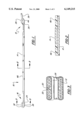
- FIG. 1 is a side elevational view of the sling
- FIG. 2 is a sectional view taken along line 2--2 in FIG. 1;
- FIG. 3 is a sectional view taken along line 3--3 in FIG. 1;
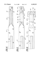
- FIG. 4 is an enlarged plan view of the end portion showing the formation of the tongue
- FIG. 5 is a plan view similar to FIG. 4 with the abrasion resistant cover encasing the tongue portion;
- FIG. 6 is a plan view of an eye with the tongue end sewn to the woven nylon webbing and the metal fastener attached;
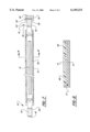
- FIG. 7 is a plan view of the sling in a mold.
- FIG. 8 is a sectional view taken along line 8--8 in FIG. 7.
- the sling 10 for a vehicle frame turnover machine are made from a woven nylon webbing 12 that is three inches wide and has a working load limit of 4800 pounds when lifting a load vertically or 9600 pounds when lifting a load as a basket.
- additional slings can be used or the woven webbing 12 can be changed.
- the nylon webbing 12 specified above is for light and medium duty truck frames.
- Slings for lighter or heavier vehicle frames and attached components can be made from nylon webbing that has a smaller or larger working load limit rating due to a change in width or a change in the thickness of the webbing.
- a change in the thickness of nylon webbing 12 may be obtained by adding additional plys of woven nylon during the manufacturing process.
- the length of the woven webbing 12 depends upon the frame turnover machine that is used and the vehicle frame dimensions.
- the slings 10 generally have a total length including the eyes of 16 feet.
- a strip of blue carboxalated nitrile roughtop 14 is sewn to one side of the webbing 12. This strip of roughtop 14 is between 11/2" and 2" wide and about 12 feet long.
- the roughtop 14 is a three ply material with a rough upper or top surface that has a coefficient of friction of 0.9 when in contact with steel. In addition to the ability of the roughtop 14 to hold vehicle frames and thereby reduce sliding contact with the frames, the roughtop has high abrasion resistance compared to other flexible belting materials.
- the ends 16 and 18 of the woven nylon webbing 12 have their sides 20 and 22 folded over and sewn together to form tongues 24 and 26 that are two layers of nylon webbing thick and between 15/8 and 2 inches wide.
- An abrasion resistant woven sleeve 28 is pulled over or slit and wrapped around each of the tongues 24 and 26.
- This sleeve 28 is woven from nylon filaments which frizz as they become scuffed and worn forming a thicker and more protective shield.
- Two rows of side stitches 30 and a row of center stitches 32 extend the length of the sleeve 28 and secure the sleeve to each side and the center of each of the tongues 24 and 26.
- Transverse stitches 34 and 36 close the ends of the tubular sleeve 28.
- a metal connector 38 has an aperture 40 that receives the tongue 24 or 26 and the sleeve 28 that encases the tongue.
- the free end of the tongue 24 is folded back and sewn to the adjacent end of the 3" wide portion of the webbing 12 to form an eye 42 on one end of the webbing.
- the free end of the tongue 26 is also folded back and sewn to the adjacent end of the 3" wide portion of the webbing 12 to form an eye 44 on the other end of the webbing.
- the metal connector 38 has four projections 46 with spaces between them. These projections are interlaced with projections 48 of a second connector and a transverse pivot pin connects the two connectors together.
- the second connector is secured to a drum of a vehicle frame turnover machine. Each drum of the vehicle frame turnover machine has a similar second connector attached.
- the first and second connectors 38 and are made from a high strength aluminum such as 6061-T6.
- the sling 10 is placed in a mold 51 for encapsulation in urethane 66.
- the mold has a flat horizontal floor that supports the sling 10 with the attached belt of blue carboxalated nitrile roughtop 14 facing upward.
- the sling is secured to the mold floor with a space between the mold walls and the edges of the woven webbing 12.
- the sides of the mold have upper edges that are slightly below the upper surface of the roughtop 14.
- the mold is filled with poured urethane 66 and the urethane is allowed to cure.
- a 95 durometer poured urethane 66 has been found to work well.
- the cure time is about twenty-four hours.
Landscapes
- Chemical & Material Sciences (AREA)
- Organic Chemistry (AREA)
- Engineering & Computer Science (AREA)
- Mechanical Engineering (AREA)
- Load-Engaging Elements For Cranes (AREA)
Abstract
Description
Claims (17)
Priority Applications (1)
| Application Number | Priority Date | Filing Date | Title |
|---|---|---|---|
| US09/348,087 US6149215A (en) | 1998-07-07 | 1999-07-06 | Durable slings for vehicle frame turnover machines and method of making the slings |
Applications Claiming Priority (2)
| Application Number | Priority Date | Filing Date | Title |
|---|---|---|---|
| US9194998P | 1998-07-07 | 1998-07-07 | |
| US09/348,087 US6149215A (en) | 1998-07-07 | 1999-07-06 | Durable slings for vehicle frame turnover machines and method of making the slings |
Publications (1)
| Publication Number | Publication Date |
|---|---|
| US6149215A true US6149215A (en) | 2000-11-21 |
Family
ID=26784504
Family Applications (1)
| Application Number | Title | Priority Date | Filing Date |
|---|---|---|---|
| US09/348,087 Expired - Fee Related US6149215A (en) | 1998-07-07 | 1999-07-06 | Durable slings for vehicle frame turnover machines and method of making the slings |
Country Status (1)
| Country | Link |
|---|---|
| US (1) | US6149215A (en) |
Cited By (19)
| Publication number | Priority date | Publication date | Assignee | Title |
|---|---|---|---|---|
| US6601890B1 (en) * | 2000-11-28 | 2003-08-05 | Safe Shop Tools, Inc. | Cylinder lifting sling and method for making the same |
| US20050062303A1 (en) * | 2001-12-03 | 2005-03-24 | Mammut Tec Ag | Lifting belt sling |
| US20080125295A1 (en) * | 2006-11-28 | 2008-05-29 | Mccrane, Inc., Dba Harbinger | Lifting Strap with Enhanced Gripping Properties |
| US20080120755A1 (en) * | 2006-11-28 | 2008-05-29 | Mccrane, Inc., Dba Harbinger | Lifting strap with wrist support and enhanced gripping properties |
| US20090184223A1 (en) * | 2008-01-21 | 2009-07-23 | Solon Se | Fixing device for photovoltaic modules on sloping roofs |
| US7628435B1 (en) * | 2005-02-16 | 2009-12-08 | Murdock Webbing Co., Inc. | Web section, round sling made from the web section, and method of making the round sling |
| US7658423B1 (en) | 2003-11-25 | 2010-02-09 | Carmichael Daniel T | Lifting sling adapted to effectuate cargo security |
| US7669904B1 (en) | 2003-11-25 | 2010-03-02 | Carmichael Daniel T | Lifting sling having a tenacious coating with methods of manufacturing and monitoring the same |
| US20100327615A1 (en) * | 2009-06-24 | 2010-12-30 | Dongguan Ponsa Textile Limited | Textile sling and method of manufacturing same |
| US20130061429A1 (en) * | 2011-09-13 | 2013-03-14 | Zedel | Method for manufacturing a strap ring for climbing activities, from a tubular fabric axially cut up |
| JP2014184792A (en) * | 2013-03-22 | 2014-10-02 | Autoliv Development Ab | Curtain airbag device |
| US9597996B2 (en) | 2014-08-15 | 2017-03-21 | Lift-All Company, Inc. | Sling protection pad |
| US20180249645A1 (en) * | 2016-09-08 | 2018-09-06 | Lawns Etc. LLC | Tarp Tool |
| US10364131B2 (en) * | 2014-06-23 | 2019-07-30 | Actuant Corporation | Double synthetic sling |
| US10494231B1 (en) * | 2019-04-02 | 2019-12-03 | Lift-All Company, Inc. | Woven strap with out of service marker |
| US20220097842A1 (en) * | 2020-09-28 | 2022-03-31 | Travis Kunkel | Rugged unmanned airborne vehicle |
| WO2022099758A1 (en) * | 2020-11-14 | 2022-05-19 | 苏州中兴华涵建筑设计有限公司 | Novel wear-resistant sling |
| US20220161978A1 (en) * | 2020-11-24 | 2022-05-26 | Idea Makers, LLC | Self-binding equipment ties |
| US11869363B1 (en) * | 2019-09-17 | 2024-01-09 | Travis Kunkel | System and method for autonomous vehicle and method for swapping autonomous vehicle during operation |
Citations (7)
| Publication number | Priority date | Publication date | Assignee | Title |
|---|---|---|---|---|
| US3290083A (en) * | 1965-05-19 | 1966-12-06 | Wear Flex Corp | Fabric load lifting sling |
| US4039217A (en) * | 1969-12-19 | 1977-08-02 | Bryant John G | Clutch pads |
| US4052095A (en) * | 1975-11-05 | 1977-10-04 | Buffalo Weaving And Belting Co. | Synthetic organic polymeric sling protected by vulcanized or cured elastomeric laminate at load contacting area thereof |
| US4171840A (en) * | 1978-01-23 | 1979-10-23 | Berzenye Michael L | Protective coated wire rope sling and method for making same |
| US4239271A (en) * | 1978-11-27 | 1980-12-16 | Banks Wire Rope Slings, Inc. | Loop for flexible strap |
| US5498047A (en) * | 1993-05-06 | 1996-03-12 | Spanset Inter Ag | Textile lifting sling with reinforcement |
| US5785146A (en) * | 1995-05-18 | 1998-07-28 | International Champion Techniques, Inc. | Arboreal climbing and support method and apparatus |
-
1999
- 1999-07-06 US US09/348,087 patent/US6149215A/en not_active Expired - Fee Related
Patent Citations (7)
| Publication number | Priority date | Publication date | Assignee | Title |
|---|---|---|---|---|
| US3290083A (en) * | 1965-05-19 | 1966-12-06 | Wear Flex Corp | Fabric load lifting sling |
| US4039217A (en) * | 1969-12-19 | 1977-08-02 | Bryant John G | Clutch pads |
| US4052095A (en) * | 1975-11-05 | 1977-10-04 | Buffalo Weaving And Belting Co. | Synthetic organic polymeric sling protected by vulcanized or cured elastomeric laminate at load contacting area thereof |
| US4171840A (en) * | 1978-01-23 | 1979-10-23 | Berzenye Michael L | Protective coated wire rope sling and method for making same |
| US4239271A (en) * | 1978-11-27 | 1980-12-16 | Banks Wire Rope Slings, Inc. | Loop for flexible strap |
| US5498047A (en) * | 1993-05-06 | 1996-03-12 | Spanset Inter Ag | Textile lifting sling with reinforcement |
| US5785146A (en) * | 1995-05-18 | 1998-07-28 | International Champion Techniques, Inc. | Arboreal climbing and support method and apparatus |
Cited By (31)
| Publication number | Priority date | Publication date | Assignee | Title |
|---|---|---|---|---|
| US20060003103A1 (en) * | 2000-11-28 | 2006-01-05 | Safe Shop Tools, Inc. | Cylinder lifting sling and method for making the same |
| US6601890B1 (en) * | 2000-11-28 | 2003-08-05 | Safe Shop Tools, Inc. | Cylinder lifting sling and method for making the same |
| US7637549B2 (en) * | 2001-12-03 | 2009-12-29 | Mamutec Ag | Lifting sling |
| US20050062303A1 (en) * | 2001-12-03 | 2005-03-24 | Mammut Tec Ag | Lifting belt sling |
| US8342584B1 (en) | 2003-11-25 | 2013-01-01 | Carmichael Daniel T | Method of manufacturing a lifting sling |
| US7669904B1 (en) | 2003-11-25 | 2010-03-02 | Carmichael Daniel T | Lifting sling having a tenacious coating with methods of manufacturing and monitoring the same |
| US7658423B1 (en) | 2003-11-25 | 2010-02-09 | Carmichael Daniel T | Lifting sling adapted to effectuate cargo security |
| US7628435B1 (en) * | 2005-02-16 | 2009-12-08 | Murdock Webbing Co., Inc. | Web section, round sling made from the web section, and method of making the round sling |
| US7891717B2 (en) | 2005-02-16 | 2011-02-22 | Murdock Webbing Co., Inc. | Web section, round sling made from the web section, and method of making the round sling |
| US20100038924A1 (en) * | 2005-02-16 | 2010-02-18 | Murdock Webbing Co., Inc. | Web section, round sling made from the web section, and method of making the round sling |
| US20080125295A1 (en) * | 2006-11-28 | 2008-05-29 | Mccrane, Inc., Dba Harbinger | Lifting Strap with Enhanced Gripping Properties |
| US20080120755A1 (en) * | 2006-11-28 | 2008-05-29 | Mccrane, Inc., Dba Harbinger | Lifting strap with wrist support and enhanced gripping properties |
| US9931533B2 (en) | 2006-11-28 | 2018-04-03 | Implus Footcare, Llc | Lifting strap with enhanced gripping properties |
| US8747284B2 (en) * | 2006-11-28 | 2014-06-10 | Mccrane, Inc. | Lifting strap with enhanced gripping properties |
| US9962572B2 (en) * | 2006-11-28 | 2018-05-08 | Implus Footcare, Llc | Lifting strap with wrist support and enhanced gripping properties |
| US7963074B2 (en) * | 2008-01-21 | 2011-06-21 | Solon Se | Fixing device for photovoltaic modules on sloping roofs |
| US20090184223A1 (en) * | 2008-01-21 | 2009-07-23 | Solon Se | Fixing device for photovoltaic modules on sloping roofs |
| US20100327615A1 (en) * | 2009-06-24 | 2010-12-30 | Dongguan Ponsa Textile Limited | Textile sling and method of manufacturing same |
| US8973509B2 (en) * | 2011-09-12 | 2015-03-10 | Zedel | Method for manufacturing a strap ring for climbing activities, from a tubular fabric axially cut up |
| US20130061429A1 (en) * | 2011-09-13 | 2013-03-14 | Zedel | Method for manufacturing a strap ring for climbing activities, from a tubular fabric axially cut up |
| JP2014184792A (en) * | 2013-03-22 | 2014-10-02 | Autoliv Development Ab | Curtain airbag device |
| US10364131B2 (en) * | 2014-06-23 | 2019-07-30 | Actuant Corporation | Double synthetic sling |
| US9597996B2 (en) | 2014-08-15 | 2017-03-21 | Lift-All Company, Inc. | Sling protection pad |
| US20180249645A1 (en) * | 2016-09-08 | 2018-09-06 | Lawns Etc. LLC | Tarp Tool |
| US10638673B2 (en) * | 2016-09-08 | 2020-05-05 | Lawns Etc. LLC | User strap for tarp |
| US10494231B1 (en) * | 2019-04-02 | 2019-12-03 | Lift-All Company, Inc. | Woven strap with out of service marker |
| US11869363B1 (en) * | 2019-09-17 | 2024-01-09 | Travis Kunkel | System and method for autonomous vehicle and method for swapping autonomous vehicle during operation |
| US20220097842A1 (en) * | 2020-09-28 | 2022-03-31 | Travis Kunkel | Rugged unmanned airborne vehicle |
| WO2022099758A1 (en) * | 2020-11-14 | 2022-05-19 | 苏州中兴华涵建筑设计有限公司 | Novel wear-resistant sling |
| US20220161978A1 (en) * | 2020-11-24 | 2022-05-26 | Idea Makers, LLC | Self-binding equipment ties |
| US11577894B2 (en) * | 2020-11-24 | 2023-02-14 | Idea Makers, LLC | Self-binding equipment ties |
Similar Documents
| Publication | Publication Date | Title |
|---|---|---|
| US6149215A (en) | Durable slings for vehicle frame turnover machines and method of making the slings | |
| US5219636A (en) | Cut and abrasion resistant webbing | |
| US5419951A (en) | Cut and abrasion resistant webbing and multifilament bicomponent yarn used in the manufacturing thereof | |
| US4856837A (en) | Reinforced cargo sling and method | |
| DE69728614T2 (en) | Run-flat tires and process for its production | |
| AU593070B2 (en) | Reinforced composite structure | |
| ATE176883T1 (en) | COVERED ABRASIVE BELT WITH ENDLESS, BAND-FREE BACKING AND MANUFACTURING METHOD | |
| US3290083A (en) | Fabric load lifting sling | |
| EP0384376B1 (en) | Elastic endless crawler | |
| US4441748A (en) | Strip thimble | |
| JPS61188205A (en) | Pneumatic tire for car | |
| RU2127704C1 (en) | Textile lifting band with reinforced edges | |
| DE2851002A1 (en) | VEHICLE TIRES | |
| DE2623072A1 (en) | RADIALLY CURRENT INSERTS OF PNEUMATIC TIRE | |
| US5141101A (en) | Conveyor belt construction | |
| US5238278A (en) | Textile lifting sling | |
| US4022070A (en) | Endless power transmission belt | |
| USRE26704E (en) | Norton fabric load lifting sling | |
| DE60213324T2 (en) | Heavy duty tire with damping unit between bead core and rim | |
| US4045072A (en) | Abrasion resistant boot | |
| US4124244A (en) | Protective pads for overhead lifting | |
| US2113561A (en) | Belt | |
| CA1075044A (en) | V-belt | |
| US4873889A (en) | Tie bar with internal lubrication | |
| US4676369A (en) | Spiral link belt with protected edges |
Legal Events
| Date | Code | Title | Description |
|---|---|---|---|
| AS | Assignment |
Owner name: DP BROWN OF DETROIT INCORPORATED, MICHIGAN Free format text: ASSIGNMENT OF ASSIGNORS INTEREST;ASSIGNORS:BALOGH, DENNIS J.;MURLICK, WILLIAM D.;REEL/FRAME:010202/0563 Effective date: 19990810 |
|
| FEPP | Fee payment procedure |
Free format text: PAYOR NUMBER ASSIGNED (ORIGINAL EVENT CODE: ASPN); ENTITY STATUS OF PATENT OWNER: SMALL ENTITY |
|
| FPAY | Fee payment |
Year of fee payment: 4 |
|
| REMI | Maintenance fee reminder mailed | ||
| FPAY | Fee payment |
Year of fee payment: 8 |
|
| SULP | Surcharge for late payment |
Year of fee payment: 7 |
|
| REMI | Maintenance fee reminder mailed | ||
| LAPS | Lapse for failure to pay maintenance fees | ||
| STCH | Information on status: patent discontinuation |
Free format text: PATENT EXPIRED DUE TO NONPAYMENT OF MAINTENANCE FEES UNDER 37 CFR 1.362 |
|
| FP | Lapsed due to failure to pay maintenance fee |
Effective date: 20121121 |