US6147971A - Optimized routing method based on minimal hop count for use in PNNI based asynchronous transfer mode networks - Google Patents
Optimized routing method based on minimal hop count for use in PNNI based asynchronous transfer mode networks Download PDFInfo
- Publication number
- US6147971A US6147971A US09/195,342 US19534298A US6147971A US 6147971 A US6147971 A US 6147971A US 19534298 A US19534298 A US 19534298A US 6147971 A US6147971 A US 6147971A
- Authority
- US
- United States
- Prior art keywords
- node
- ptse
- route
- routing
- network
- Prior art date
- Legal status (The legal status is an assumption and is not a legal conclusion. Google has not performed a legal analysis and makes no representation as to the accuracy of the status listed.)
- Expired - Lifetime
Links
Images

Classifications
-
- H—ELECTRICITY
- H04—ELECTRIC COMMUNICATION TECHNIQUE
- H04L—TRANSMISSION OF DIGITAL INFORMATION, e.g. TELEGRAPHIC COMMUNICATION
- H04L45/00—Routing or path finding of packets in data switching networks
- H04L45/02—Topology update or discovery
-
- H—ELECTRICITY
- H04—ELECTRIC COMMUNICATION TECHNIQUE
- H04L—TRANSMISSION OF DIGITAL INFORMATION, e.g. TELEGRAPHIC COMMUNICATION
- H04L45/00—Routing or path finding of packets in data switching networks
- H04L45/02—Topology update or discovery
- H04L45/10—Routing in connection-oriented networks, e.g. X.25 or ATM
Definitions
- the present invention relates generally to data communication networks and more particularly relates to a method of improving the performance of routing algorithms used in PNNI based ATM networks based on optimizing on minimal hop count.
- ATM Asynchronous Transfer Mode
- ATM originated as a telecommunication concept defined by the Comite Consulatif International Circuitique et Telephonique (CCITT), now known as the ITU, and the American National Standards Institute (ANSI) for carrying user traffic on any User to Network Interface (UNI) and to facilitate multimedia networking between high speed devices at multi-megabit data rates.
- CITT Comite Consulatif International Circuitique et Telephonique
- ANSI American National Standards Institute
- ATM is a method for transferring network traffic, including voice, video and data, at high speed.
- switched networking technology centered around a switch, a great number of virtual connections can be supported by multiple applications through the same physical connection.
- the switching technology enables bandwidth to be dedicated for each application, overcoming the problems that exist in a shared media networking technology, like Ethernet, Token Ring and Fiber Distributed Data Interface (FDDI).
- FDDI Fiber Distributed Data Interface
- ATM allows different types of physical layer technology to share the same higher layer--the ATM layer.
- ATM uses very short, fixed length packets called cells.
- the first five bytes, called the header, of each cell contain the information necessary to deliver the cell to its destination.
- the cell header also provides the network with the ability to implement congestion control and traffic management mechanisms.
- the fixed length cells offer -smaller and more predictable switching delays as cell switching is less complex than variable length packet switching and can be accomplished in hardware for many cells in parallel.
- the cell format also allows for multi-protocol transmissions. Since ATM is protocol transparent, the various protocols can be transported at the same time. With ATM, phone, fax, video, data and other information can be transported simultaneously.
- ATM is a connection oriented transport service. To access the ATM network, a station requests a virtual circuit between itself and other end stations, using the signaling protocol to the ATM switch.
- ATM provides the User Network Interface (UNI) which is typically used to interconnect an ATM user with an ATM switch that is managed as part of the same network.
- UNI User Network Interface
- PNNI Private Network Node Interface
- IISP Interim Inter-Switch Signaling Protocol
- the Interim Local Management Interface (ILMI) for the PNNI protocol specification provides an auto-port configuration capability. This capability functions to minimize manual configuration operations for PNNI ports of switches.
- the Phase 0 solution to auto-port configuration is based on hop by hop routing utilizing a ⁇ best match ⁇ scheme.
- the Phase 1 PNNI based solution is based on Open Shortest Path First (OSPF) with the additions necessary for ATM.
- OSPF Open Shortest Path First
- This scheme is essentially a ⁇ source routing ⁇ scheme whereby each node has basic knowledge of the structure of the entire network and uses this knowledge to build a complete path from the source to the destination.
- OSPF Open Shortest Path First
- This scheme is essentially a ⁇ source routing ⁇ scheme whereby each node has basic knowledge of the structure of the entire network and uses this knowledge to build a complete path from the source to the destination.
- OSPF Open Shortest Path First
- This scheme is essentially a ⁇ source routing ⁇ scheme whereby each node has basic knowledge of the structure of the entire
- the ATM nodes in the network route the signaling SETUP message hop by hop (i.e., node by node) using a ⁇ best match ⁇ scheme.
- ATM addresses are 20 bytes long but only 19 bytes can be used for routing purposes.
- several prefixes of the ATM address for each link can be registered.
- a node i.e., an ATM switch
- a disadvantage of this scheme is that all the prefixes of all neighboring nodes must be registered manually on each of the respective ports. For example, if a port is disconnected from a neighbor and connected to a new neighbor, then the registered addresses must be manually changed in both nodes.
- This type of network can be termed an absolutely static network.
- the PNNI protocol Phase 1 has been developed for use between private ATM switches and between groups of private ATM switches.
- the PNNI specification includes two categories of protocols.
- the first protocol is defined for the distribution of topology information between switches and clusters of switches where the information is used to compute routing paths within the network.
- the main feature of the PNNI hierarchy mechanism is its ability to automatically configure itself within the networks in which the address structure reflects the topology.
- the PNNI topology and routing techniques are based on the well known link state routing technique.
- the second protocol is effective for signaling, i.e., the message flows used to establish point-to-point and point-to-multipoint connections across the ATM network.
- This protocol is based on the ATM Forum User to Network Interface (UNI) signaling with mechanisms added to support source routing, crankback and alternate routing of source SETUP requests in the case of bad connections
- the PNNI hierarchy begins at the lowest level where the lowest level nodes are organized into peer groups.
- a logical node in the context of the lowest hierarchy level is the lowest level node.
- a logical node is typically denoted as simply a node.
- a peer group is a collection of logical nodes wherein each node within the group exchanges information with the other members of the group such that all members maintain an identical view of the group.
- VCC Virtual Channel Connection
- RRC PNNI Routing Control Channel
- Hello messages are sent periodically by each node on this link. In this fashion the Hello protocol makes the two neighboring nodes known to each other.
- Each node exchanges Hello packets with its immediate neighbors to determine its neighbor's local state information.
- the state information includes the identity and peer group membership of the node's immediate neighbors and a status of its links to its neighbors.
- Each node then bundles its state information in one or more PNNI Topology State Elements (PTSEs) which are subsequently flooded throughout the peer group.
- PTSEs PNNI Topology State Elements
- PTSEs are the smallest collection of PNNI routing information that is flooded as a unit among all logical nodes within a peer group.
- a node topology database consists of a collection of all PTSEs received, which represent that particular node's present view of the PNNI routing topology.
- the topology database provides all the information required to compute a route from the given source node to any destination address reachable in or through that routing domain.
- a topology database includes detailed topology information about the peer group in which the logical node resides in addition to more abstract topology information representing the remainder of the PNNI routing domain.
- the nodes in question first exchange PTSE header information, i.e., they advertise the presence of PTSEs in their respective topology databases.
- a node receives PTSE header information that advertises a more recent PTSE version than the one that it has already or advertises a PTSE that it does not yet have, it requests the advertised PTSE and updates its topology database with the subsequently received PTSE.
- the ensuing database synchronization reduces to a one way topology database copy.
- a link is advertised by a PTSE transmission only after the database synchronization between the respective neighboring nodes has successfully completed. In this fashion, the link state parameters are. distributed to all topology databases in the peer group.
- PTSEs are encapsulated within PNNI Topology State Packets (PTSPs) for transmission.
- PTSPs PNNI Topology State Packets
- Each PTSE is acknowledged by encapsulating information from its PTSE header within the acknowledgment packet that is sent back to the sending neighbor If the PTSE is new or of more recent origin then the node's current copy, the PTSE is installed in the topology database and flooded to all neighboring nodes except the one from which the PTSE was received.
- a PTSE sent to a neighbor is periodically retransmitted until acknowledged,
- flooding is an ongoing activity wherein each node issues PTSPs with PTSEs that contain updated information.
- the PTSEs contain the topology databases and are subject to aging and get removed after a predefined duration if they are not refreshed by a new incoming PTSE. Only the node that originally originated a particular PTSE can re-originate that PTSE. PTSEs are reissued both periodically and on an event driven basis.
- a node when a node first learns about the existence of a neighboring peer node which resides in the same peer group, it initiates the database exchange process in order to synchronize its topology database with that of its neighbor's.
- the database exchange process involves exchanging a sequence of database summary packets that contain the identifying information of all PTSEs in a node topology database.
- the database summary packet performs an exchange utilizing a lock step mechanism whereby one side sends a database summary packet and the other side responds with its own database summary packet, thus acknowledging the received packet.
- a node When a node receives a database summary packet from its neighboring peer, it first examines its topology database for the presence of each PTSE described within the packet. If the particular PTSE is not found in its topology database or if the neighboring peer has a more recent version of the PTSE then the node requests the PTSE from the particular neighboring peer or optionally from another neighboring peer whose database summary indicates that it has the most recent version of the PTSE.
- a corresponding neighboring peer data structure is maintained by the nodes located on either side of the link.
- the neighboring peer data structure includes information required to maintain database synchronization and flooding to neighboring peers.
- both nodes on either side of the link begin in the Neighboring Peer Down state.
- the event AddPort is triggered in the corresponding neighboring peer state machine.
- the event DropPort is triggered in the corresponding neighboring peering state machine.
- the database exchange process commences with the event AddPort that is thus triggered but only after the first link between the two neighboring peers is up.
- the neighboring peer state machine will internally generate the DropPort last event closing all state information for the neighboring peers to be cleared.
- the fast step is taken in creating an adjacency between two neighboring peer nodes.
- the master which is the slave and it is also in this state that an initial Database Summary (DS) sequence number is decided upon.
- DS Database Summary
- the Exchanging state is entered. In this state the node describes is topology database to the neighboring peer by sending database summary packets to it.
- the database summary packets contain summaries of the topology state information contained in the node's database.
- the database summary packets contain summaries of the topology state information contained in the node's database.
- those portions of the topology database that where originated or received at the level of the logical group node or at higher levels are included in the database summary.
- the PTSP and PTSE header information of each such PTSE is listed in one of the nodes database packets. PTSEs for which new instances are received after the exchanging status have been entered may not be included in any database summary packet since they will be handled by the normal flooding procedures.
- the incoming data base summary packet on the receive side is associated with a neighboring peer via the interface over which it was received.
- Each database summary packet has a database summary sequence number that is implicitly acknowledged.
- the node looks up the PTSE in its database to see whether it also has an instance of that particular PTSE. If it does not or if the database copy is less recent, then the node either re-originates the newer instance of the PTSE or flushes the PTSE from the routing domain after installing it in the topology database with a remaining lifetime set accordingly.
- the PTSP and PTSE header contents in the PTSE summary are accepted as a newer or updated PTSE with empty contents. If the PTSE is not found in the node's topology database, the particular PTSE is put on the PTSE request list so it can be requested from a neighboring peer via one or more PTSE request packets.
- the PTSE request list contains a list of those PTSEs that need to be obtained in order to synchronize that particular node's topology database with the neighboring peer's topology database.
- the PTSE request list packets are only sent during the Exchanging state and the Loading state.
- the node can sent a PTSE request pack to a neighboring peer and optionally to any other neighboring peers that are also in either the Exchanging state or the Loading state and whose database summary indicate that they have the missing PTSEs.
- the received PTSE request packets specify a list of PTSEs that the neighboring peer wishes to receive. For each PTSE specified in the PTSE request packet, its instance is looked up in the node's topology database. The requested PTSEs are subsequently bundled into PTSPs and transmitted to the neighboring peer. Once the last PTSE and the PTSE request list has been received, the node moves from the Loading state to the Full state. Once the Full state has been reached, the node has received all PTSEs known to be available from its neighboring peer and links to the neighboring peer can now be advertised within PTSEs.
- IISP is a method of routing and performing auto registration (auto configuration) in an ATM network.
- the method simplifies the configuration and routing for ATM networks having a relatively large number of nodes.
- Networks are constructed in hierarchical fashion in the form of branches and trees and assigned network address prefixes in accordance with their location in the network.
- Network nodes periodically exchange identification information permitting both switches on either side of a link to be aware of who they are connected to.
- Each node registers a network address and an associated significant length for each of its neighbors on each of its links.
- a node performs routing by comparing the destination address against each of its registered addresses for all its links.
- the routing method takes advantage of the network address prefix to ensure that the routing proceeds in the correct direction towards the destination and does not enter a tree or a branch that does not contain the destination.
- each node performs load balancing at each point in the routing process.
- a node can generate crankback messages if the routing leads to a dead end.
- each node knows who its neighbors are. This is accomplished by each node sending out on all its NNI ports an identification message that comprises the address prefix assigned to it and its significant length. This message is sent out periodically (e.g., every second). The nodes that receive it compare the address prefix in the message to the special NNI type address that is registered on the port the message was received on. If the addresses do not match or there is no NNI address registered, then the node makes the received address prefix the new registered NNI address for that port and changes its routing tables accordingly. If the address do match, the message is ignored.
- Each node sending out identification messages on a periodic basis automatically permits the node to almost immediately detect if it becomes connected to a new neighbor. If a change is detected, the nodes modifies its routing tables accordingly.
- each node address prefix is unique and is assigned in hierarchical fashion as described above, it is guaranteed that either the local address prefix (i.e., the address prefix of the node itself) or the remote node address prefix will be smaller.
- the IISP signaling specification requires that one side of a link be denoted as the USER and the other side as the NETWORK.
- the USER the other side
- the NETWORK the significant length of the local prefix (i.e., of the node itself) is shorter than that of a neighbor, then the local side is set as the NETWORK.
- This particular link attribute setting allows the signaling to automatic align after a dynamic link replacement when a nodes neighbors are changed.
- the transfer of addresses can be performed manually at each node or can be performed in accordance with ILMI registration procedures.
- PNNI PNNI only fall address matching is permitted, i e., an address must filly match the address entry in the topology database.
- IISP permits partial address matching.
- the IISP routing method is a partially static routing scheme.
- PNNI Networks can be constructed that comprise peer groups having from dozens to over a hundred nodes. The concept is tat many nodes in the same peer group can be represented as one node in a higher level of the hierarchy. Since PNNI utilizes a link state, source routing type routing scheme wherein each node has a view of the entire network, it is the hierarchy that permits the division of the network view into smaller chunks. In PNNI, very large portions of the network comprising a large number of nodes may be viewed by nodes in other peer groups as a single logical node.
- routes can be calculated from source to destination users.
- a routing algorithm that is commonly used to determine the optimum route from a source node to a destination node is the Dijkstra algorithm.
- the Dijkstra algorithm is used to generate the Designated Transit List that is the routing list used by each node in the path during the setup phase of the call.
- Used in the algorithm are the topology database (link state database) which includes the PTSEs received from each node, a Path List comprising a list of nodes for which the best path from the source node has been found and a Tentative List comprising a list of nodes that are only possibly the best paths. Once it is determined that a path is in fact the best possible, the node is moved from the Tentative List to the Path List.
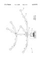
- FIG. 1 A diagram illustrating an example ATM network consisting of a plurality of nodes and a source user connected to a local node is shown in FIG. 1.
- the example network generally referenced 10, comprises a plurality of nodes 16, each labeled by a different letter.
- a source user 14 is connected to a local node 12.
- Nodes are connected via links between them with the link cost represented by a number shown next to each link. Note that the cost of a link corresponds to the links resources, e.g., its capacity. Links with lower costs are preferred over links with higher costs.
- node A is considered the destination node.
- the algorithm begins with the source node (self) as the root of a tree by placing the source node ID onto the Path List. Next, for each node N placed in the Path List, examine N's nearest neighbors. For each neighbor M, add the cost of the path from the root to N to the cost of the link from N to M. If M is not already in the Path List or the Tentative List with a better path cost, add M to the Tentative List.
- the algorithm terminates. Otherwise, the entry in the Tentative List with the minimum cost is found. That entry is moved to the Path List and the examination step described above is repeated.
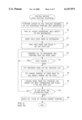
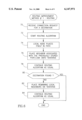
- FIG. 2 A flow diagram illustrating the prior art method of network routing using the well known Dijkstra method is shown in FIG. 2.
- the first step is to perform an address lookup (step 20) in the node's topology database on the advertised reachable prefixes and addresses to find all the nodes that advertise a ⁇ BEST MATCH ⁇ to the destination node (step 22).
- Each of the nodes found in the search is marked as a ⁇ destination ⁇ for this particular route calculation (step 24). Note that more than one node can be marked as a destination node.
- the calculations begin with the first node, i.e., the local node, which is placed on the PATH list (step 26). All the neighbors of the local node are then traversed wherein a number of metrics is accumulated for each neighbor (step 28). With reference to FIG. 1, the neighbors include nodes B, E, G and I.
- a Generic Connection Admission Control (GCAC) analysis is performed on the links to the neighbors and if a link passes the GCAC analysis (step 30), the corresponding neighbor is placed on the TENTATIVE tree which is keyed for metric optimization (step 32). In this case, four links corresponding to nodes B, E, G and I are placed on the TENTATIVE list.
- the parent pointer is then set to point back to the neighbor's parent node along the path, i.e., the node whose links were just evaluated (step 34).
- the TENTATIVE list is then sorted by the accumulated link cost as shown below in Table 1.
- a node is then chosen from the TENTATIVE list having the best optimization among all the nodes on the TENTATIVE list and placed on the PATH list (step 36). It is then checked to see if the node chosen is marked as the destination node (step 38).
- a routing list known as a Designation Transit List (DTL) stack is generated by tracing the parent pointers from the destination node back to the local node (step 40). If the node is not the destination node the method returns to step 28 and the node's neighbors are traversed.
- DTL Designation Transit List
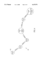
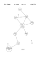
- FIG. 3 A diagram illustrating the example ATM network of FIG. 1 with parent pointers indicated connecting nodes back to the local node is shown in FIG. 3.
- Each node is shown with an allow pointing back to its parent node along the path.
- node E was randomly selected (note that the cost of nodes E, G, I are identical). Since node E is not the destination. The neighbors of node E are then examined, i.e., nodes D, F, H and G. The accumulated cost back to the local node of each link is then examined. Links having lower cost are selected over those having higher costs.
- the TENTATIVE list is shown in Table 2 below.
- the algorithm builds a plurality of DTL stacks, with a final decision being made, for some topologies, after almost all the nodes are traversed.
- the optimum DTL stack is then chosen after all possible paths to the destination have been uncovered and examined. In this fashion every node in the network and its corresponding links is examined until the optimum path is found.
- the routing algorithm described above must be performed in response to a SETUP request from a user.
- the attached node must perform the route calculations each time, regardless of the destination address.
- Running a routing algorithm such as Dijkstra, however, consumes computing resources in terms of memory and processor time. As was seen in the example above, almost the entire network was traversed to generate the DTL stack to the destination node A. If the routes could be cached, the route calculation time and the resource utilization would be greatly reduced.
- each node functions to create information units known as PTSEs whereby the node described itself, its local links, local addresses and local proprietary information.
- PTSEs information units
- each node attains knowledge of the entire topology of the network by storing these PTSEs in its database. It is important to point out, however, that one or more PTSEs may change and which have not as yet been received by every node in the network as the nodes are in the midst of being flooded. Therefore, it is more accurate to say that each node almost learns about the entire topology of the network
- the route can be calculated either by (1) using a pre-route calculation, i.e., a route that was calculated beforehand or by (2) using a route calculation for a specific destination on demand, with the optional use of caching.
- any suitable routing algorithm may be utilized.
- Some routing algorithms that can be used include, but are not limited to, Belman-Ford and Dijkstra.
- the Dijkstra algorithm is preferred for performance reasons wherein the resulting complexity is O(N 2 ).
- Other typical routing algorithms operate around a complexity of O(N 3 ).
- a problem, however, associated with the Dijkstra algorithm is that it ⁇ spreads ⁇ out from the local node in performing the route calculation like ⁇ fire in a field of thorns. ⁇
- the algorithm star from the local node A and during each iteration, it expands one hop further from the local node. Since a specific destination was requested, the ⁇ best ⁇ node from the TENTATIVE node list is chosen, in accordance with the optimization.
- FIG. 4 A diagram illustrating an example ATM network having a local node and a destination node whereby a route is calculated to the destination using the first method of the present invention is shown in FIG. 4.
- the example ATM network generally referenced 50, comprises a plurality of nodes 52 represented by different letters.
- a local node A is connected to neighboring nodes E, F (the destination node), B, C and D.
- the cost associated with each node is also shown,
- the local node chooses the next node to put on PATH without knowledge of whether that node will lead to the destination. Assuming the optimization is performed in accordance with the cost and if the destination node to route to is node F, then the node likely to be put on PATH is node B since the cost of the link is one compared with ten for the link between local node A and node E. The node does not yet ⁇ know ⁇ that this path leads to a dead end and will not yield a path to the destination for this specific configuration. In particular, Dijkstra will traverse nodes B, C and D before it realizes that none of these nodes along this path lead to the destination.
- the present invention overcomes the problems of the prior art discussed above by providing two solutions for optimizing the algorithm used by the local node in calculating the route to a destination node.
- a first method optimizes the route calculation by associating a port/link information with the PTSEs received by the node.
- a second method optimizes the route calculation by utilizing a special PTSE termed a ROUTE -- PTSE into which is placed the route the PTSE takes upon being flooded from the creating node. It is important to point out that the first and second method of the present invention is suitable for optimizations that are based on MINIMAL hop count optimizations and is suited only for UBR type calls as no optimizations are performed on cell delay, etc.
- a node may support either or both methods. If a node supports both, then if the second method fails, the node can still utilize the first method.
- the originating node In the first method of the present invention, the originating node generates one or more PTSEs and begins the flooding process by flooding it to all its neighbors.
- the neighbors receive the PTSE, store it in their topology databases and forward it further on to the network unless that particular PTSE has previously been stored in their topology database. An association is thus made between the originating node and the port/link it was first received on.
- a request is received to route to a destination node.
- the routing algorithm e.g., Dijkstra
- the routing algorithm is altered such that the node begins searching for a route using the associated port/link that the PTSE was previously received on.
- the routing algorithm is ⁇ steered ⁇ or ⁇ pointed ⁇ in the optimum direction to start with, thus saving time in determining the optimum route to the destination.
- the second method of the present invention requires that each node supporting this method create a new PTSE termed a ROUTE -- PTSE that is flooded as usual throughout the network.
- the PTSE is sent form the originator with a header and an empty body.
- Each node along the path that supports this second method adds itself to the bottom of the list. In this fashion, a source route is constructed, from the originating node to any other node. If a node does not understand the PTSE, it stores it and floods it further on in accordance with the PNNI standard.
- Asynchronous Transfer Mode ATM network
- a method of improving the performance of a routing algorithm in calculating a route from a local node to a destination node, the nodes in the network running the Private Network to Network Interface (PNNI) protocol comprising the steps of generating a PNNI Topology State Element (PTSE) on an originating node and flushing the PTSE throughout the network, receiving the PTSE at a local node, associating the originating node with a port link the PTSE arrived on if the PTSE is not in a topology database within the local node or if the PTSE is in the topology database but with a lower sequence number associated thereto, placing a neighbor of the local node associated with the port/link the PTSE arrived on onto a TENTATIVE list, in accordance with a call request, the PTSE received from the originating node currently being the destination and continuing the route calculation in accordance with the routing algorithm.
- PNNI Private Network to Network Interface
- the method further comprises the steps of placing the remaining neighbors connected to the local node onto the TENTATIVE list if a destination is not found utilizing the port/ink and continuing the route calculation in accordance with the routing algorithm using the TENTATIVE list.
- the method further comprises the steps of generating a nodal PTSE upon receipt of a link PTSE indicating that a link has come up or gone down, waiting a period of time, the period of time chosen randomly from a predetermined time range and flooding the PTSE to the network upon the expiration of the random time period.
- an Asynchronous Transfer Mode (ATM) network a method of improving the performance of a routing algorithm in calculating a route from a local node to a destination node, the nodes in the network running the Private Network to Network Interface (PNNI) protocol, the method comprising the steps of generating a Routing PNNI Topology State Element (ROUTE -- PTSE) on an originating node and flushing the ROUTE -- PTSE throughout the network, the ROUTE -- PTSE including a routing list which is initially empty, receiving the PTSE at a node, adding the node to the routing list if a neighboring node the ROUTE -- PTSE was received from is either the originating node or the node most recently added to the routing list, calculating a best route to the last node in the routing list and adding the resulting nodes to the routing list if the neighboring node the ROUTE -- PTSE was received from is neither the originating node nor the node most recently added to the
- ATM Asynchronous Transfer Mode
- FIG. 1 is a diagram illustrating an example ATM network consisting of a plurality of nodes and a source user connected to a local node;
- FIG. 2 is a flow diagram illustrating the prior art method of network routing using the well known Dijkstra method
- FIG. 3 is a diagram illustrating the example ATM network of FIG. 1 with parent pointers indicated connecting nodes back to the local node;
- FIG. 4 is a diagram illustrating an example ATM network having a local node and a destination node whereby a route is calculated to the destination using the first method of the present invention
- FIG. 5 is a flow diagram illustrating the PTSE portion of a first method of the present invention for improving the performance of the route calculation wherein PTSE information is used to optimize routing;
- FIG. 6 is a flow diagram illustrating the routing portion of the first method of the present invention for improving the performance of the route calculation
- FIG. 7 is a diagram illustrating an example ATM network having a local node and a destination node whereby a route is calculated to the destination using the second method of the invention
- FIG. 8 is a flow diagram illustrating the PTSE portion of a second method of the present invention for improving the performance of the route calculation wherein PTSE information is used to optimize routing;
- FIG. 9 is a flow diagram illustrating the routing portion of the second method of the present invention for improving the performance of the route calculation.
- the present invention provides two solutions for opt s the algorithm used by the local node in calculating the route to a destination node.
- a first method optimizes the route calculation by associating a port/link information with the PTSEs received by the node.
- a second method optimizes the route calculation by utilizing a special PTSE termed a ROUTE -- PTSE into which is placed the route the PTSE takes upon being flooded from the creating node.
- a node may support either or both methods. If a node supports both, then if the second method fails, the node can still utilize the first method.
- the creating node generates one or more PTSEs and begins the flooding process by flooding it to all its neighbors.
- the neighbors receive the PTSE, store it in their topology databases and forward it further on to the network unless that particular PTSE has previously been stored in their topology database.
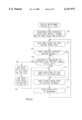
- FIG. 5 A flow diagram illustrating the PTSE portion of a first method of the present invention for improving the performance of the route calculation wherein PTSE information is used to optimize routing is shown in FIG. 5.
- the first step is that a node receives a PTSE from a neighboring node on one of its ports (step 60).
- the node receives the PTSE (any PTSE) from its neighbor, it examines who the originator of the PTSE is. It then checks whether that PTSE is already in its topology database (step 62).
- the node checks whether the PTSE in the topology database is older, i.e,, has a lower sequence number, than the PTSE just received (step 64). If the PTSE in the topology database does has a lower sequence number or the PTSE is not in the database, than the node associates the originating node wit the port/link the PTSE arrived on (step 66). If it does not, the PTSE is neither stored nor flooded. Note that the originating node is typically not a neighbor of the receiving node. This association is stored in the node's database and is used at a later time when there is a request to perform a route calculation to the originating node.
- a request is received to route to a destination node.
- the routing algorithm e.g., Dijkstra
- the routing algorithm is altered such that the node begins searching for a route using the associated port/link that the PTSE was previously received on.
- the routing algorithm is ⁇ steered ⁇ or ⁇ pointed ⁇ in the optimum direction to start with, thus saving time in determining the optimum route to the destination. This is done by putting only that port's neighbor on the TENTATIVE list and if the destination was not found, then the remaining neighbors are put on TENTATIVE.
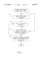
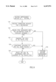
- a flow diagram illustrating the routing portion of the first method of the present invention for improving the performance of the route calculation is shown in FIG. 6.
- the routing algorithm such as Dijkstra is then started in response to the request (step 72).
- the local port begins the routing algorithm, it puts itself in the PATH (step 74). It then traverses its neighbors and puts them on TENTATIVE.
- the local node only puts the neighbor that was previously associated with the destination port on the TENTATIVE list (step 76).
- the routing algorithm e.g., Dijkstra, continues as usual in search of the destination node (step 78).
- step 80 the method terminates. If, however, the destination was not found, the remaining local neighbors are placed on the TENTATIVE list (step 82) and the algorithm continues as usual (step 84). Note that the destination may not be found even if the correct neighbor node, i.e., the node associated with the port/link that the PTSE from the destination (originating) node came in on, was put on TENTATIVE since the GCAC may have failed.
- the first method is operative to cause the routing algorithm to start with the port associated with the PTSE received from the destination port because it is assumed that this port is the ⁇ closest ⁇ or fastest way to the destination. It is highly probable that the PTSE received first from an originating node took the shortest path therefrom. Thus, the port/link association is made using this first PTSE. Note, however, that the destination may be not reachable using the associated port/link at the time the connection request is received.
- the first PTSE to arrive at a node may not have taken the shortest or optimal route from the originating node. It is possible that there are other ports that can lead to the destination. These ports, however, are probably the same or larger number of hops from the local node. A flood may or may not have been received over these other ports. The port the first flood is received on, however, is assumed to be the ⁇ closest ⁇ to the originator.
- the time saved in finding a route to the destination will vary depending on the location of the local node and the number of ports attached to it.
- the first method also comprises a means for speeding up the propagation of changes in the network such as when a link comes up or goes down.
- a node receives a link PTSE containing information concerning a link coming up or going don the node generates and floods a nodal PTSE advertising itself
- the node waits a random time within a time range, e.g., 1 to 5 seconds, before transmitting the nodal PTSE to its neighbors.
- a time range e.g. 1 to 5 seconds
- the second method of the present invention requires that each node supporting this method create a new PTSE, termed a ROUTE -- PTSE that is flooded as usual throughout the network.
- the PTSE is sent from the originator with a header and an empty body.
- Each node along the path that supports this second method adds itself to the bottom of the list. In this fashion, a source route is constructed from the originating node to any other node. If a node does not understand the PTSE, it stores it and floods it further on in accordance with the PNNI standard.
- FIG. 7 A diagram illustrating an example ATM network having a local node and a destination node whereby a route is calculated to the destination using the second method of the invention is shown in FIG. 7.
- the example network generally referenced 90, comprises a plurality of nodes 92 labeled with letters.
- the local node A is shown connected to nodes M, F, H. B and C.
- Other nodes include nodes D, K and G (the destination node).
- FIG. 8 A flow diagram illustrating the PTSE portion of a second method of the present invention for improving the performance of the route calculation wherein PTSE information is used to optimize routing is shown in FIG. 8. It is important to note that in contrast to the regular PTSE which, according to the PNNI standards, only the originating node can alter, the second method requires that all nodes supporting this feature must alter the PTSE.
- the first step is that the originating node generates and floods the ROUTE -- PTSE having a header as usual but with an empty body (step 100).
- Each node along the path receives the ROUTE -- PTSE (step 102). If the node supports the second method (step 104) it checks whether the neighbor that sent the PTSE is the originator or the node most recently added to the list (step 106).
- the node adds itself to the body of the ROUTE -- PTSE (step 110).
- the node stores the ROUTE -- PTSE in its topology database (step 112) and floods it to its neighbors (step 114).
- the method continues at the next node on the path (step 102). If the node along the path does not support the second method (step 104), it still stores it in its topology database (step 112) and floods it to its neighbors (step 114).
- the ROUTE -- PTSE originated by node G and received at local node A contains a node list similar to a DTL containing in order the following nodes: M, K and G.
- Each node along the flood path adds itself to the PTSE before flooding it to its neighbors.
- FIG. 9 A flow diagram illustrating the routing portion of the second method of the present invention for improving the performance of the route calculation is shown in FIG. 9.
- the local node receives a connection request for a particular destination (step 120).
- the node checks whether the ROUTE PTSE associated with the destination node is in its topology database (step 122). If the node is found in the database, the node then traverses the path found in the previously stored ROUTE -- PTSE (step 124).
- the originating node When the originating node receives the flush PTSE it responds by generating a new ROUTE -- PTSE and flooding it to its neighbors. A new DTL is thereby constructed and eventually arrives at the local node but with a DTL that gets around the failed link. Note that until the new ROUTE -- PTSE reaches the local node still performs the Dijkstra algorithm as usual without the benefit of the new DTL as the route must be calculated immediately upon receiving the request. Some time after the route is calculated, the new ROUTE -- PTSE is received and the topology database in the local node is updated.
Abstract
Description
              TABLE I
______________________________________
Node       Accumulated Cost
______________________________________
E          1
G          1
I          1
B          2
______________________________________
              TABLE 2
______________________________________
Node       Accumulated Cost
______________________________________
B          2
D          3
F          3
H          3
G          1
I          1
______________________________________
______________________________________
Term  Definition
______________________________________
ANSI  American National Standards Institute
ATM   Asynchronous Transfer Mode
CCITT Comite Consulatif International Telegraphique et Telephonique
DTL   Designation Transit List
FDDI  Fiber Distributed Data Interface
FSM   Finite State Machine
GCAC  Generic Connection Admission Control
IISP  Interim Inter-Switch Signaling Protocol
ILMI  Interim Local Management Interface
ITU   International Telecommunications Union
NNI   Network to Network Interface
PGL   Peer Group Leader
PNNI  Private Network to Network Interface
PTSE  PNNI Topology State Element
PTSP  PNNI Topology State Packet
RCC   Routing Control Channel
UBR   Unspecified Bit Rate
UNI   User to Network Interface
VCC   Virtual Channel Connection
______________________________________
Claims (6)
Priority Applications (3)
| Application Number | Priority Date | Filing Date | Title |
|---|---|---|---|
| US09/195,342 US6147971A (en) | 1998-11-18 | 1998-11-18 | Optimized routing method based on minimal hop count for use in PNNI based asynchronous transfer mode networks |
| AU11757/00A AU1175700A (en) | 1998-11-18 | 1999-11-15 | An optimized routing method for use in pnni based atm networks |
| PCT/IL1999/000614 WO2000030302A1 (en) | 1998-11-18 | 1999-11-15 | An optimized routing method for use in pnni based atm networks |
Applications Claiming Priority (1)
| Application Number | Priority Date | Filing Date | Title |
|---|---|---|---|
| US09/195,342 US6147971A (en) | 1998-11-18 | 1998-11-18 | Optimized routing method based on minimal hop count for use in PNNI based asynchronous transfer mode networks |
Publications (1)
| Publication Number | Publication Date |
|---|---|
| US6147971A true US6147971A (en) | 2000-11-14 |
Family
ID=22721054
Family Applications (1)
| Application Number | Title | Priority Date | Filing Date |
|---|---|---|---|
| US09/195,342 Expired - Lifetime US6147971A (en) | 1998-11-18 | 1998-11-18 | Optimized routing method based on minimal hop count for use in PNNI based asynchronous transfer mode networks |
Country Status (3)
| Country | Link |
|---|---|
| US (1) | US6147971A (en) |
| AU (1) | AU1175700A (en) |
| WO (1) | WO2000030302A1 (en) |
Cited By (41)
| Publication number | Priority date | Publication date | Assignee | Title |
|---|---|---|---|---|
| US6240463B1 (en) * | 1998-11-24 | 2001-05-29 | Lucent Technologies Inc. | Router placement methods and apparatus for designing IP networks with performance guarantees |
| US6246669B1 (en) * | 1997-11-28 | 2001-06-12 | Cisco Technology, Inc. | Method and system for optimizing connection set-up operations in a high speed digital network |
| US20010043624A1 (en) * | 2000-02-25 | 2001-11-22 | Atsuko Saito | Switching system and routing method |
| US20020012318A1 (en) * | 2000-06-07 | 2002-01-31 | Ryuichi Moriya | Network managing method, network node apparatus, and mesh-type network |
| US20020083174A1 (en) * | 2000-12-21 | 2002-06-27 | Shinichi Hayashi | Traffic engineering method and node apparatus using traffic engineering method |
| US6463053B1 (en) * | 1998-12-01 | 2002-10-08 | Nortel Networks Limited | Voice-and-fax-over IP dialing plan |
| US20020172157A1 (en) * | 2001-03-12 | 2002-11-21 | Rhodes David L. | Method and system for fast computation of routes under multiple network states with communication continuation |
| US20020181402A1 (en) * | 2001-05-31 | 2002-12-05 | Lemoff Brian E. | Adaptive path discovery process for routing data packets in a multinode network |
| US20020194256A1 (en) * | 2001-05-31 | 2002-12-19 | Needham Bradford H. | Limiting request propagation in a distributed file system |
| US20030023751A1 (en) * | 2001-07-11 | 2003-01-30 | Tsunehito Mouri | Plural-routes search method and network system using the same |
| WO2003009544A1 (en) * | 2001-07-17 | 2003-01-30 | Intel Corporation | Bus protocol |
| US20030123532A1 (en) * | 2002-01-03 | 2003-07-03 | Mauritz Karl H. | Network fabric physical layer |
| WO2003063422A1 (en) * | 2002-01-20 | 2003-07-31 | General Instrument Corporation | Method and apparatus for priority-based load balancing for use in an extended local area network |
| US20030193901A1 (en) * | 2002-04-11 | 2003-10-16 | Nec Corporation | Communication network control system, control method, node and program |
| US6757258B1 (en) * | 2000-05-04 | 2004-06-29 | Cisco Technology, Inc. | Method and apparatus for reducing OSPF flooding |
| US6765863B1 (en) * | 2000-02-28 | 2004-07-20 | Fujitsu Limited | Network system |
| US20040160941A1 (en) * | 2003-02-17 | 2004-08-19 | Samsung Electronics Co., Ltd. | Method for calculating hop count of mobile IP in an IP network |
| US6857026B1 (en) * | 1999-12-14 | 2005-02-15 | Nortel Networks Limited | Using alternate routes for fail-over in a communication network |
| US20050047353A1 (en) * | 2003-08-25 | 2005-03-03 | Susan Hares | Systems and methods for routing employing link state and path vector techniques |
| US20050105470A1 (en) * | 2001-11-30 | 2005-05-19 | Francesco Lazzeri | Telecommunications network control method and network with said system |
| US6914877B1 (en) * | 1999-09-30 | 2005-07-05 | Lucent Technologies Inc. | System for alerting a network of changes in operational status of communication links |
| US20050163135A1 (en) * | 2004-01-23 | 2005-07-28 | Hopkins Samuel P. | Method for improving peer to peer network communication |
| US20060034298A1 (en) * | 2004-08-16 | 2006-02-16 | Eric Rosenberg | Private network-to-network interface |
| US20060034289A1 (en) * | 2004-08-16 | 2006-02-16 | Eric Rosenberg | Private network-to-network interface |
| US7002906B1 (en) * | 1998-08-28 | 2006-02-21 | Cisco Technology, Inc. | Method for extending the crankback procedure to any Asynchronous Transfer Mode system |
| US7039014B1 (en) * | 2000-12-26 | 2006-05-02 | Cisco Technology, Inc. | Network-wide connection-based debug mechanism |
| US7065093B1 (en) * | 2001-05-17 | 2006-06-20 | Cisco Technology, Inc | Method and apparatus for end-to-end ATM calls based on the interworking of ATM switched virtual circuit signaling with Q.2630.1 AAL2 signaling |
| US20060218301A1 (en) * | 2000-01-25 | 2006-09-28 | Cisco Technology, Inc. | Methods and apparatus for maintaining a map of node relationships for a network |
| US20070004876A1 (en) * | 2005-06-22 | 2007-01-04 | Fina Technology, Inc. | Cocatalysts for olefin polymerizations |
| US20070003720A1 (en) * | 2005-06-22 | 2007-01-04 | Fina Technology, Inc. | Cocatalysts useful for preparing polyethylene pipe |
| US20070004875A1 (en) * | 2005-06-22 | 2007-01-04 | Fina Technology, Inc. | Cocatalysts useful for improving polyethylene film properties |
| DE102006007070B3 (en) * | 2006-02-15 | 2007-06-21 | Siemens Ag | Method of determining transmission paths or routes of a communication network transmitting data packets and having several nodes with bidirectional ports |
| US20070160039A1 (en) * | 2005-06-15 | 2007-07-12 | Xu Huiying | Method for identifying node reachability, method for identifying whether a link is an external link, method for calculating a routing, and method for disseminating node address information |
| US20070178904A1 (en) * | 2006-01-31 | 2007-08-02 | Fujitsu Limited | Call system |
| US7701860B2 (en) * | 2003-02-21 | 2010-04-20 | Alcatel Lucent | Control plane stability in communications networks |
| US7801048B1 (en) * | 2004-06-23 | 2010-09-21 | Cisco Technology, Inc. | Concurrent path computation using virtual shortest path tree |
| US20110286358A1 (en) * | 2008-12-16 | 2011-11-24 | ZTE Corporation ZTE Plaza, Keji Road South | Method and device for establishing a route of a connection |
| US20120063362A1 (en) * | 2010-09-09 | 2012-03-15 | Thippanna Hongal | Method and apparatus for computing paths to destinations in networks having link constraints |
| US8156175B2 (en) | 2004-01-23 | 2012-04-10 | Tiversa Inc. | System and method for searching for specific types of people or information on a peer-to-peer network |
| US9922330B2 (en) | 2007-04-12 | 2018-03-20 | Kroll Information Assurance, Llc | System and method for advertising on a peer-to-peer network |
| US20220052938A1 (en) * | 2020-08-11 | 2022-02-17 | Hewlett Packard Enterprise Development Lp | System and method for eliminating data loss in a virtually aggregated network |
Families Citing this family (1)
| Publication number | Priority date | Publication date | Assignee | Title |
|---|---|---|---|---|
| US7428221B2 (en) * | 2004-06-01 | 2008-09-23 | Cisco Technology, Inc. | Arrangement for providing network prefix information from attached mobile routers to a clusterhead in a tree-based ad hoc mobile network |
Citations (9)
| Publication number | Priority date | Publication date | Assignee | Title |
|---|---|---|---|---|
| US5117422A (en) * | 1990-07-09 | 1992-05-26 | Itt Corporation | Method for providing an efficient and adaptive management of message routing in a multi-platform and apparatus communication system |
| US5323394A (en) * | 1992-04-07 | 1994-06-21 | Digital Equipment Corporation | Selecting optimal routes in source routing bridging without exponential flooding of explorer packets |
| US5491690A (en) * | 1993-07-30 | 1996-02-13 | International Business Machines Corporation | Method and apparatus to speed up the path selection in a packet switching network |
| US5535195A (en) * | 1994-05-06 | 1996-07-09 | Motorola, Inc. | Method for efficient aggregation of link metrics |
| US5600638A (en) * | 1993-12-22 | 1997-02-04 | International Business Machines Corporation | Method and system for improving the processing time of the path selection in a high speed packet switching network |
| US5699347A (en) * | 1995-11-17 | 1997-12-16 | Bay Networks, Inc. | Method and apparatus for routing packets in networks having connection-oriented subnetworks |
| US5781529A (en) * | 1996-03-27 | 1998-07-14 | General Datacomm, Inc. | Systems and methods for routing ATM switched virtual circuit calls |
| US5805593A (en) * | 1995-09-26 | 1998-09-08 | At&T Corp | Routing method for setting up a service between an origination node and a destination node in a connection-communications network |
| US5831982A (en) * | 1995-12-21 | 1998-11-03 | Siemens Aktiengesellschaft | Method for forming routing information in an ATM communication network |
-
1998
- 1998-11-18 US US09/195,342 patent/US6147971A/en not_active Expired - Lifetime
-
1999
- 1999-11-15 WO PCT/IL1999/000614 patent/WO2000030302A1/en active Application Filing
- 1999-11-15 AU AU11757/00A patent/AU1175700A/en not_active Abandoned
Patent Citations (9)
| Publication number | Priority date | Publication date | Assignee | Title |
|---|---|---|---|---|
| US5117422A (en) * | 1990-07-09 | 1992-05-26 | Itt Corporation | Method for providing an efficient and adaptive management of message routing in a multi-platform and apparatus communication system |
| US5323394A (en) * | 1992-04-07 | 1994-06-21 | Digital Equipment Corporation | Selecting optimal routes in source routing bridging without exponential flooding of explorer packets |
| US5491690A (en) * | 1993-07-30 | 1996-02-13 | International Business Machines Corporation | Method and apparatus to speed up the path selection in a packet switching network |
| US5600638A (en) * | 1993-12-22 | 1997-02-04 | International Business Machines Corporation | Method and system for improving the processing time of the path selection in a high speed packet switching network |
| US5535195A (en) * | 1994-05-06 | 1996-07-09 | Motorola, Inc. | Method for efficient aggregation of link metrics |
| US5805593A (en) * | 1995-09-26 | 1998-09-08 | At&T Corp | Routing method for setting up a service between an origination node and a destination node in a connection-communications network |
| US5699347A (en) * | 1995-11-17 | 1997-12-16 | Bay Networks, Inc. | Method and apparatus for routing packets in networks having connection-oriented subnetworks |
| US5831982A (en) * | 1995-12-21 | 1998-11-03 | Siemens Aktiengesellschaft | Method for forming routing information in an ATM communication network |
| US5781529A (en) * | 1996-03-27 | 1998-07-14 | General Datacomm, Inc. | Systems and methods for routing ATM switched virtual circuit calls |
Cited By (80)
| Publication number | Priority date | Publication date | Assignee | Title |
|---|---|---|---|---|
| US6246669B1 (en) * | 1997-11-28 | 2001-06-12 | Cisco Technology, Inc. | Method and system for optimizing connection set-up operations in a high speed digital network |
| US7002906B1 (en) * | 1998-08-28 | 2006-02-21 | Cisco Technology, Inc. | Method for extending the crankback procedure to any Asynchronous Transfer Mode system |
| US6240463B1 (en) * | 1998-11-24 | 2001-05-29 | Lucent Technologies Inc. | Router placement methods and apparatus for designing IP networks with performance guarantees |
| US6463053B1 (en) * | 1998-12-01 | 2002-10-08 | Nortel Networks Limited | Voice-and-fax-over IP dialing plan |
| US6914877B1 (en) * | 1999-09-30 | 2005-07-05 | Lucent Technologies Inc. | System for alerting a network of changes in operational status of communication links |
| US6857026B1 (en) * | 1999-12-14 | 2005-02-15 | Nortel Networks Limited | Using alternate routes for fail-over in a communication network |
| US7984137B2 (en) * | 2000-01-25 | 2011-07-19 | Cisco Technology, Inc. | Methods and apparatus for maintaining a map of node relationships for a network |
| US20060218301A1 (en) * | 2000-01-25 | 2006-09-28 | Cisco Technology, Inc. | Methods and apparatus for maintaining a map of node relationships for a network |
| US20010043624A1 (en) * | 2000-02-25 | 2001-11-22 | Atsuko Saito | Switching system and routing method |
| US6765863B1 (en) * | 2000-02-28 | 2004-07-20 | Fujitsu Limited | Network system |
| US6757258B1 (en) * | 2000-05-04 | 2004-06-29 | Cisco Technology, Inc. | Method and apparatus for reducing OSPF flooding |
| US20020012318A1 (en) * | 2000-06-07 | 2002-01-31 | Ryuichi Moriya | Network managing method, network node apparatus, and mesh-type network |
| US7302494B2 (en) * | 2000-12-21 | 2007-11-27 | Fujitsu Limited | Traffic engineering method and node apparatus using traffic engineering method |
| US20020083174A1 (en) * | 2000-12-21 | 2002-06-27 | Shinichi Hayashi | Traffic engineering method and node apparatus using traffic engineering method |
| US7039014B1 (en) * | 2000-12-26 | 2006-05-02 | Cisco Technology, Inc. | Network-wide connection-based debug mechanism |
| US7848245B1 (en) | 2000-12-26 | 2010-12-07 | Cisco Technology, Inc | Network-wide connection-based debug mechanism |
| US7158486B2 (en) * | 2001-03-12 | 2007-01-02 | Opcoast Llc | Method and system for fast computation of routes under multiple network states with communication continuation |
| US20020172157A1 (en) * | 2001-03-12 | 2002-11-21 | Rhodes David L. | Method and system for fast computation of routes under multiple network states with communication continuation |
| US7065093B1 (en) * | 2001-05-17 | 2006-06-20 | Cisco Technology, Inc | Method and apparatus for end-to-end ATM calls based on the interworking of ATM switched virtual circuit signaling with Q.2630.1 AAL2 signaling |
| US7660317B2 (en) | 2001-05-17 | 2010-02-09 | Cisco Technology, Inc. | Establishing calls using Q.2630.1 AAL2 signaling responsive to private network-network interface (PNNI) signaling |
| US20060239284A1 (en) * | 2001-05-17 | 2006-10-26 | Cisco Technology, Inc. | Establishing calls using Q.2630.1 AAL2 signaling responsive to private network-network interface (PNNI) signaling |
| US6990111B2 (en) | 2001-05-31 | 2006-01-24 | Agilent Technologies, Inc. | Adaptive path discovery process for routing data packets in a multinode network |
| US6839769B2 (en) * | 2001-05-31 | 2005-01-04 | Intel Corporation | Limiting request propagation in a distributed file system |
| US20020181402A1 (en) * | 2001-05-31 | 2002-12-05 | Lemoff Brian E. | Adaptive path discovery process for routing data packets in a multinode network |
| US20020194256A1 (en) * | 2001-05-31 | 2002-12-19 | Needham Bradford H. | Limiting request propagation in a distributed file system |
| US7219159B2 (en) * | 2001-07-11 | 2007-05-15 | Fujitsu Limited | Plural-routes search method and network system using the same |
| US20030023751A1 (en) * | 2001-07-11 | 2003-01-30 | Tsunehito Mouri | Plural-routes search method and network system using the same |
| WO2003009544A1 (en) * | 2001-07-17 | 2003-01-30 | Intel Corporation | Bus protocol |
| US6853620B2 (en) * | 2001-07-17 | 2005-02-08 | Intel Corporation | Bus protocol |
| CN100464531C (en) * | 2001-07-17 | 2009-02-25 | 英特尔公司 | Bus protocol |
| US20050105470A1 (en) * | 2001-11-30 | 2005-05-19 | Francesco Lazzeri | Telecommunications network control method and network with said system |
| US7346099B2 (en) | 2002-01-03 | 2008-03-18 | Intel Corporation | Network fabric physical layer |
| US20030123532A1 (en) * | 2002-01-03 | 2003-07-03 | Mauritz Karl H. | Network fabric physical layer |
| WO2003063422A1 (en) * | 2002-01-20 | 2003-07-31 | General Instrument Corporation | Method and apparatus for priority-based load balancing for use in an extended local area network |
| US6717950B2 (en) * | 2002-01-20 | 2004-04-06 | General Instrument Corporation | Method and apparatus for priority-based load balancing for use in an extended local area network |
| US20030193901A1 (en) * | 2002-04-11 | 2003-10-16 | Nec Corporation | Communication network control system, control method, node and program |
| US7366112B2 (en) * | 2002-04-11 | 2008-04-29 | Nec Corporation | Communication network control system, control method, node and program |
| US20080031140A1 (en) * | 2003-02-17 | 2008-02-07 | Samsung Electronics Co., Ltd. | Method for calculating hop count of mobile ip in an ip network |
| US20040160941A1 (en) * | 2003-02-17 | 2004-08-19 | Samsung Electronics Co., Ltd. | Method for calculating hop count of mobile IP in an IP network |
| KR100929101B1 (en) * | 2003-02-17 | 2009-11-30 | 삼성전자주식회사 | How to calculate hop of mobile IP in IP network |
| US7450582B2 (en) * | 2003-02-17 | 2008-11-11 | Samsung Electronics Co., Ltd | Method for calculating hop count of mobile IP in an IP network |
| US7701860B2 (en) * | 2003-02-21 | 2010-04-20 | Alcatel Lucent | Control plane stability in communications networks |
| WO2005022311A3 (en) * | 2003-08-25 | 2006-02-02 | Nexthop Technologies Inc | Systems and methods for routing employing link state and path vector techniques |
| US20050047353A1 (en) * | 2003-08-25 | 2005-03-03 | Susan Hares | Systems and methods for routing employing link state and path vector techniques |
| WO2005022311A2 (en) * | 2003-08-25 | 2005-03-10 | Nexthop Technologies, Inc. | Systems and methods for routing employing link state and path vector techniques |
| US8122133B2 (en) | 2004-01-23 | 2012-02-21 | Tiversa, Inc. | Method for monitoring and providing information over a peer to peer network |
| US20070153710A1 (en) * | 2004-01-23 | 2007-07-05 | Tiversa, Inc. | Method for monitoring and providing information over a peer to peer network |
| US8798016B2 (en) * | 2004-01-23 | 2014-08-05 | Tiversa Ip, Inc. | Method for improving peer to peer network communication |
| US20050163050A1 (en) * | 2004-01-23 | 2005-07-28 | Hopkins Samuel P. | Method for monitoring and providing information over a peer to peer network |
| US8037176B2 (en) | 2004-01-23 | 2011-10-11 | Tiversa, Inc. | Method for monitoring and providing information over a peer to peer network |
| US8386613B2 (en) | 2004-01-23 | 2013-02-26 | Tiversa Ip, Inc. | Method for monitoring and providing information over a peer to peer network |
| US20050163135A1 (en) * | 2004-01-23 | 2005-07-28 | Hopkins Samuel P. | Method for improving peer to peer network communication |
| US8156175B2 (en) | 2004-01-23 | 2012-04-10 | Tiversa Inc. | System and method for searching for specific types of people or information on a peer-to-peer network |
| US7583682B2 (en) * | 2004-01-23 | 2009-09-01 | Tiversa, Inc. | Method for improving peer to peer network communication |
| US8819237B2 (en) | 2004-01-23 | 2014-08-26 | Tiversa Ip, Inc. | Method for monitoring and providing information over a peer to peer network |
| US8312080B2 (en) | 2004-01-23 | 2012-11-13 | Tiversa Ip, Inc. | System and method for searching for specific types of people or information on a peer to-peer network |
| US20100042732A1 (en) * | 2004-01-23 | 2010-02-18 | Hopkins Samuel P | Method for improving peer to peer network communication |
| US8468250B2 (en) | 2004-01-23 | 2013-06-18 | Tiversa Ip, Inc. | Method for monitoring and providing information over a peer to peer network |
| US7761569B2 (en) | 2004-01-23 | 2010-07-20 | Tiversa, Inc. | Method for monitoring and providing information over a peer to peer network |
| US20110029660A1 (en) * | 2004-01-23 | 2011-02-03 | Tiversa, Inc. | Method for monitoring and providing information over a peer to peer network |
| US7783749B2 (en) | 2004-01-23 | 2010-08-24 | Tiversa, Inc. | Method for monitoring and providing information over a peer to peer network |
| US8358641B2 (en) | 2004-01-23 | 2013-01-22 | Tiversa Ip, Inc. | Method for improving peer to peer network communication |
| US7801048B1 (en) * | 2004-06-23 | 2010-09-21 | Cisco Technology, Inc. | Concurrent path computation using virtual shortest path tree |
| US7453813B2 (en) * | 2004-08-16 | 2008-11-18 | At&T Corp. | Methods for constructing PNNI networks with optimized architecture |
| US20060034298A1 (en) * | 2004-08-16 | 2006-02-16 | Eric Rosenberg | Private network-to-network interface |
| US7403485B2 (en) * | 2004-08-16 | 2008-07-22 | At&T Corp. | Optimum construction of a private network-to-network interface |
| US20060034289A1 (en) * | 2004-08-16 | 2006-02-16 | Eric Rosenberg | Private network-to-network interface |
| US20070160039A1 (en) * | 2005-06-15 | 2007-07-12 | Xu Huiying | Method for identifying node reachability, method for identifying whether a link is an external link, method for calculating a routing, and method for disseminating node address information |
| US7782798B2 (en) * | 2005-06-15 | 2010-08-24 | Huawei Technologies, Co., Ltd. | Method for identifying node reachability, method for identifying whether a link is an external link, method for calculating a routing, and method for disseminating node address information |
| US20070004875A1 (en) * | 2005-06-22 | 2007-01-04 | Fina Technology, Inc. | Cocatalysts useful for improving polyethylene film properties |
| US20070003720A1 (en) * | 2005-06-22 | 2007-01-04 | Fina Technology, Inc. | Cocatalysts useful for preparing polyethylene pipe |
| US20070004876A1 (en) * | 2005-06-22 | 2007-01-04 | Fina Technology, Inc. | Cocatalysts for olefin polymerizations |
| US20070178904A1 (en) * | 2006-01-31 | 2007-08-02 | Fujitsu Limited | Call system |
| US8010125B2 (en) * | 2006-01-31 | 2011-08-30 | Fujitsu Limited | Call system |
| DE102006007070B3 (en) * | 2006-02-15 | 2007-06-21 | Siemens Ag | Method of determining transmission paths or routes of a communication network transmitting data packets and having several nodes with bidirectional ports |
| US9922330B2 (en) | 2007-04-12 | 2018-03-20 | Kroll Information Assurance, Llc | System and method for advertising on a peer-to-peer network |
| US20110286358A1 (en) * | 2008-12-16 | 2011-11-24 | ZTE Corporation ZTE Plaza, Keji Road South | Method and device for establishing a route of a connection |
| US8509217B2 (en) * | 2008-12-16 | 2013-08-13 | Zte Corporation | Method and device for establishing a route of a connection |
| US20120063362A1 (en) * | 2010-09-09 | 2012-03-15 | Thippanna Hongal | Method and apparatus for computing paths to destinations in networks having link constraints |
| US20220052938A1 (en) * | 2020-08-11 | 2022-02-17 | Hewlett Packard Enterprise Development Lp | System and method for eliminating data loss in a virtually aggregated network |
Also Published As
| Publication number | Publication date |
|---|---|
| WO2000030302B1 (en) | 2000-09-08 |
| AU1175700A (en) | 2000-06-05 |
| WO2000030302A1 (en) | 2000-05-25 |
Similar Documents
| Publication | Publication Date | Title |
|---|---|---|
| US6147971A (en) | Optimized routing method based on minimal hop count for use in PNNI based asynchronous transfer mode networks | |
| US6208623B1 (en) | Method of combining PNNI and E-IISP in an asynchronous transfer mode network | |
| US6614757B1 (en) | Method of local flow control in an asynchronous transfer mode network utilizing PNNI routing protocol | |
| US6577653B1 (en) | Apparatus for and method of establishing a route utilizing multiple parallel segments in an asynchronous transfer mode network | |
| US6396842B1 (en) | Method of searching using longest match based Randix Search Trie with variable length keys and having prefix capability | |
| US6178172B1 (en) | Method of topology database synchronization in an asynchronous transfer mode network | |
| US6483808B1 (en) | Method of optimizing routing decisions over multiple parameters utilizing fuzzy logic | |
| US7123620B1 (en) | Apparatus and method for scalable and dynamic traffic engineering in a data communication network | |
| US6473408B1 (en) | Building a hierarchy in an asynchronous transfer mode PNNI network utilizing proxy SVCC-based RCC entities | |
| US6711152B1 (en) | Routing over large clouds | |
| US6262984B1 (en) | Method of preventing overlapping branches in point to multipoint calls in PNNI networks | |
| US6456600B1 (en) | Complex node representation in an asynchronous transfer mode PNNI network | |
| US6532237B1 (en) | Apparatus for and method of testing a hierarchical PNNI based ATM network | |
| US5953312A (en) | Method and apparatus for determining alternate routes in a network using a connection-oriented protocol | |
| EP1579716B1 (en) | Routing scheme based on virtual space representation | |
| US6683874B1 (en) | Router device and label switched path control method using upstream initiated aggregation | |
| US8467394B2 (en) | Automatic route tagging of BGP next-hop routes in IGP | |
| US7079493B2 (en) | Device and method for collecting traffic information | |
| JP3319972B2 (en) | System and method for hierarchical multicast routing in ATM networks | |
| US20020018447A1 (en) | Method and system for routing packets over parallel links between neighbor nodes | |
| US20020181402A1 (en) | Adaptive path discovery process for routing data packets in a multinode network | |
| US6470022B1 (en) | Method of distributing network resources fairly between users in an asynchronous transfer mode network | |
| US7120119B2 (en) | Management of protocol information in PNNI hierarchical networks | |
| US6212188B1 (en) | Method of source routing in an asynchronous transfer mode network when a node is in an overload state | |
| EP1009130A1 (en) | Distributed directory services for locating network resources in a very large packet switching network |
Legal Events
| Date | Code | Title | Description |
|---|---|---|---|
| AS | Assignment |
Owner name: 3COM CORPORATION, CALIFORNIA Free format text: ASSIGNMENT OF ASSIGNORS INTEREST;ASSIGNORS:ROCHBERGER, HAIM;OR, ALEXANDER;REEL/FRAME:009777/0992 Effective date: 19990203 |
|
| STCF | Information on status: patent grant |
Free format text: PATENTED CASE |
|
| FPAY | Fee payment |
Year of fee payment: 4 |
|
| FEPP | Fee payment procedure |
Free format text: PAYOR NUMBER ASSIGNED (ORIGINAL EVENT CODE: ASPN); ENTITY STATUS OF PATENT OWNER: LARGE ENTITY Free format text: PAYER NUMBER DE-ASSIGNED (ORIGINAL EVENT CODE: RMPN); ENTITY STATUS OF PATENT OWNER: LARGE ENTITY |
|
| FPAY | Fee payment |
Year of fee payment: 8 |
|
| AS | Assignment |
Owner name: HEWLETT-PACKARD COMPANY, CALIFORNIA Free format text: MERGER;ASSIGNOR:3COM CORPORATION;REEL/FRAME:024630/0820 Effective date: 20100428 |
|
| AS | Assignment |
Owner name: HEWLETT-PACKARD COMPANY, CALIFORNIA Free format text: CORRECTIVE ASSIGNMENT TO CORRECT THE SEE ATTACHED;ASSIGNOR:3COM CORPORATION;REEL/FRAME:025039/0844 Effective date: 20100428 |
|
| AS | Assignment |
Owner name: HEWLETT-PACKARD DEVELOPMENT COMPANY, L.P., TEXAS Free format text: ASSIGNMENT OF ASSIGNORS INTEREST;ASSIGNOR:HEWLETT-PACKARD COMPANY;REEL/FRAME:027329/0044 Effective date: 20030131 |
|
| AS | Assignment |
Owner name: HEWLETT-PACKARD DEVELOPMENT COMPANY, L.P., TEXAS Free format text: CORRECTIVE ASSIGNMENT PREVIUOSLY RECORDED ON REEL 027329 FRAME 0001 AND 0044;ASSIGNOR:HEWLETT-PACKARD COMPANY;REEL/FRAME:028911/0846 Effective date: 20111010 |
|
| FPAY | Fee payment |
Year of fee payment: 12 |
|
| AS | Assignment |
Owner name: HEWLETT PACKARD ENTERPRISE DEVELOPMENT LP, TEXAS Free format text: ASSIGNMENT OF ASSIGNORS INTEREST;ASSIGNOR:HEWLETT-PACKARD DEVELOPMENT COMPANY, L.P.;REEL/FRAME:037079/0001 Effective date: 20151027 |