US6139026A - Stabilized "O" ring gasket seal - Google Patents
Stabilized "O" ring gasket seal Download PDFInfo
- Publication number
- US6139026A US6139026A US09/276,199 US27619999A US6139026A US 6139026 A US6139026 A US 6139026A US 27619999 A US27619999 A US 27619999A US 6139026 A US6139026 A US 6139026A
- Authority
- US
- United States
- Prior art keywords
- fluoropolymer
- ring
- sheet
- parallel surfaces
- outside
- Prior art date
- Legal status (The legal status is an assumption and is not a legal conclusion. Google has not performed a legal analysis and makes no representation as to the accuracy of the status listed.)
- Expired - Fee Related
Links
Images


Classifications
-
- F—MECHANICAL ENGINEERING; LIGHTING; HEATING; WEAPONS; BLASTING
- F16—ENGINEERING ELEMENTS AND UNITS; GENERAL MEASURES FOR PRODUCING AND MAINTAINING EFFECTIVE FUNCTIONING OF MACHINES OR INSTALLATIONS; THERMAL INSULATION IN GENERAL
- F16L—PIPES; JOINTS OR FITTINGS FOR PIPES; SUPPORTS FOR PIPES, CABLES OR PROTECTIVE TUBING; MEANS FOR THERMAL INSULATION IN GENERAL
- F16L23/00—Flanged joints
- F16L23/16—Flanged joints characterised by the sealing means
- F16L23/18—Flanged joints characterised by the sealing means the sealing means being rings
-
- F—MECHANICAL ENGINEERING; LIGHTING; HEATING; WEAPONS; BLASTING
- F16—ENGINEERING ELEMENTS AND UNITS; GENERAL MEASURES FOR PRODUCING AND MAINTAINING EFFECTIVE FUNCTIONING OF MACHINES OR INSTALLATIONS; THERMAL INSULATION IN GENERAL
- F16L—PIPES; JOINTS OR FITTINGS FOR PIPES; SUPPORTS FOR PIPES, CABLES OR PROTECTIVE TUBING; MEANS FOR THERMAL INSULATION IN GENERAL
- F16L23/00—Flanged joints
- F16L23/16—Flanged joints characterised by the sealing means
-
- Y—GENERAL TAGGING OF NEW TECHNOLOGICAL DEVELOPMENTS; GENERAL TAGGING OF CROSS-SECTIONAL TECHNOLOGIES SPANNING OVER SEVERAL SECTIONS OF THE IPC; TECHNICAL SUBJECTS COVERED BY FORMER USPC CROSS-REFERENCE ART COLLECTIONS [XRACs] AND DIGESTS
- Y10—TECHNICAL SUBJECTS COVERED BY FORMER USPC
- Y10S—TECHNICAL SUBJECTS COVERED BY FORMER USPC CROSS-REFERENCE ART COLLECTIONS [XRACs] AND DIGESTS
- Y10S277/00—Seal for a joint or juncture
- Y10S277/905—T-Shaped or I-shaped ring member including seal on a side
-
- Y—GENERAL TAGGING OF NEW TECHNOLOGICAL DEVELOPMENTS; GENERAL TAGGING OF CROSS-SECTIONAL TECHNOLOGIES SPANNING OVER SEVERAL SECTIONS OF THE IPC; TECHNICAL SUBJECTS COVERED BY FORMER USPC CROSS-REFERENCE ART COLLECTIONS [XRACs] AND DIGESTS
- Y10—TECHNICAL SUBJECTS COVERED BY FORMER USPC
- Y10S—TECHNICAL SUBJECTS COVERED BY FORMER USPC CROSS-REFERENCE ART COLLECTIONS [XRACs] AND DIGESTS
- Y10S277/00—Seal for a joint or juncture
- Y10S277/91—O-ring seal
Definitions
- This invention relates to seals, especially for flange connections and even more especially for connections between glass lined flanges.
- Gaskets for sealing flanges together are well known in the art. Unfortunately, readily removable and cost effective gaskets for sealing flange faces have not been as good as desired, especially when the flange faces have been glass coated and surround openings in vessels or conduits having corrosive contents that are under pressure, e.g. 300 psi (about 20 atmospheres) or higher. Under such conditions, seals between flange faces have often been known to leak or even blow out. Further, such known gaskets require high seating loads that can cause glass lining failures. Such seals also require a large number of clamps or bolts in a uniform distribution around the seal area in order to maintain the high loads required.
- seals for glass and other smooth surfaces, generally use gaskets having flat surfaces that can seal at almost any location on the surface. Such seals are not as sanitary as desirable for pharmaceutical and food applications because of cracks at the edge of the contact areas between the sealing flange and gasket that can harbor contamination because the actual seal may be formed at another location on the flat gasket surface.
- PTFE polytetrafluoroethylene
- an O-ring envelope gasket was invented and awarded U.S. Pat. No. 5,556,113.
- This gasket is provided with a fluoropolymer protective sheet that covers, protects and retains an O-ring supported by a reinforcing ring comprising a metal strip between compressible layers.
- the metal ring in this gasket provides significant resistance to radial deformation or rupture ("blow out").
- gaskets as described in U.S. Pat. No. 5,556,113, are an improvement over prior gaskets for sealing glass coated flanges, they are complex to manufacture.
- the metal supporting ring and compressible layers may not have sufficient corrosion resistance to withstand attack by the contents of the container in the event that the relatively thin protective sheet is breached. It is therefore an object of the present invention to eliminate or reduce the above described problems and disadvantages associated with prior sealing gaskets for flanges, especially glass lined flanges.
- FIG. 1 shows an embodiment of the stabilized O-ring gasket seal of the invention, provided with a PTFE protective shield that is grooved to retain the O-ring.
- FIG. 2 shows an uncompressed embodiment of the stabilized O-ring gasket seal of the invention where the O-ring and reinforced PTFE back up sheets are covered by a PTFE shield.
- FIG. 3 shows the embodiment of FIG. 2 in a compressed state between a cover and glass lined flange.
- FIG. 4 shows a view of an O-ring gasket seal where the O rings rest in a depressed portions of the metal retaining ring and are further backed up on both sides by reinforced fluoropolymer sheets.
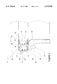
- FIG. 5 shows an embodiment of a hinge type container cover sealed to a glass coated flange by means of a stabilized O-ring gasket seal of the invention as shown in FIG. 4.
- FIG. 6 shows a magnified view of a secured end portion of the cover of FIG. 5, showing a swing bolt connection.
- the invention comprises a sealing gasket for sealing a flange face, especially flange faces that may be sensitive to uneven application of pressure or that cannot be provided with any sort of flange retaining means comprising a sharp angle in the flange surface.
- the gasket includes at least a metal ring, a reinforced fluoropolymer sheet, an O ring and a fluoropolymer protective shield.
- the metal ring is defined by inside and outside circumferences, by widely separated outwardly directed parallel surfaces that in turn define maximum thickness of the ring, by narrowly separated parallel surfaces defining opposing depressed portions in the ring and by opposing shoulders.
- Each of the shoulders connects one of the widely separated parallel surfaces to one of the narrowly separated parallel surfaces and each shoulder is perpendicular to the parallel surfaces and has a surface that faces the inside circumference.
- Each of the widely separated parallel surfaces is covered by at least one reinforced fluoropolymer sheet having inside and outside surfaces positioned so that the inside surface of the sheet faces and covers at least one of the widely separated parallel surfaces and so that the outside surface faces outwardly.
- two separate reinforced fluoropolymer sheets are provided, one of which covers one of the widely separated surfaces and the other of which covers the other widely separated surface.
- the gasket includes at least two O rings.
- the O rings have outside ring diameters about equal to a diameter of the shoulder, i.e. the distance from shoulder to shoulder across the center of the metal ring.
- the O rings have thicknesses that are sufficient to extend beyond the outside surface of the reinforced fluoropolymer sheet when each O ring is positioned so that it is at least partly within one of the parallel depressed portions, and so that the outside diameter of the O ring is proximate to and stabilized by the face of a shoulder.
- the narrowly separated parallel surfaces, the interior circumference, and the outside surface of the fluoropolymer sheets are preferably covered by a contiguous fluoropolymer protective shield to further increase resistance to corrosive compounds.
- the shield may be a film of uniform thickness or may have a variable thickness as might be obtained by molding to a desired pattern.
- the fluoropolymer protective shield at a minimum, preferably covers the outside surface of the at least one reinforced fluoropolymer sheet, the narrowly separated parallel surfaces and the inside circumference of the metal ring.
- the fluoropolymer shield may at least partially follow a contour of the depressed portions in the metal ring so that depressed portions are present in the outside surface of the fluoropolymer sheet to permit the O rings to be placed at least partly within the depressed portions of both the metal ring and fluoropolymer shield.
- the fluoropolymer protective shield may also cover the O ring.
- the metal ring used in the gasket of the invention provides significant strength against radial blow out. This is true because pressure from inside of a closed vessel applied to the metal ring is almost always applied uniformly around the inside circumference of the metal ring which would require that the force expand the circumference of the ring and stretch the ring to its break point before the ring could be breached. The internal pressure is thus resisted by the tensile strength of the metal of the ring.
- the metal of the ring is thus selected on the basis of its tensile strength and often also on the basis of corrosion resistance.
- the steel ring may simply comprise carbon steel which can have a tensile strength of from about 65,000 to about 90,000 pounds per square inch depending upon processing conditions and quantity of carbon, manganese, and silicon in the steel.
- the metal ring is preferably made from a high tensile strength, corrosion resistant metal alloy.
- Particularly preferred metals are the corrosion resistant metal alloys comprising from about 0.5 to about 78 weight percent iron, from about 12 to about 25 weight percent chromium, and from 0 to about 80 weight percent nickel.
- Such corrosion resistant alloys may also contain trace amounts, e.g.
- non-metals such as carbon, sulfur and silicon and may also contain manganese, molybdenum, cobalt or titanium, usually, but not always, in relatively low percentages, e.g. less than about 5 weight percent.
- Other metals such as corrosion resistant transition metals may also be present in low percentages, e.g. less than about 4 and usually less than about one percent.
- Commonly known names and trademarks for such corrosion resistant alloys are stainless steel, Inconel, Hastelloy, and Monel. Such corrosion resistant alloys generally have good corrosion resistance and high tensile strength, i.e. from about 70,000 pounds per square inch up to about 200,000 pounds per square inch or more.
- highly corrosion resistant metals may be used to form the ring, e.g. tantalum, palladium and palladium alloys with e.g. ruthenium and platinum, platinum and platinum alloys with e.g. iridium, rhodium, and ruthenium.
- the metal ring may be formed by any suitable means, e.g. forging, casting or machining.
- the size of the outside circumference of the metal ring is determined by the outside dimension of a flange to be sealed by the gasket; although, the metal ring may in fact have a diameter that is somewhat larger or smaller than the diameter of the flange to be sealed.
- the inside circumference of the ring i.e. the circumference defining the size of the hole through the ring, is usually determined by the inside circumference of the flange to be sealed.
- the inside circumference of the flange defines the opening size through the flange.
- the inside circumference of the metal ring is often somewhat larger than the inside circumference of the flange to be sealed to permit space for a protective fluoropolymer shield, e.g. films or sheets, covering the metal ring, without requiring the shield to extend into the opening defined by the inside circumference of the flange to be sealed.
- a protective fluoropolymer shield e.g. films or sheets
- the "widely separated" parallel surfaces (faces) that define the maximum thickness of the ring are usually, but not always, separated by a distance of from about 0.5 to about 10 centimeters and the "narrowly separated” parallel surfaces (faces) that defined opposed depressed portions in the surface of the ring are usually, but not always, separated by from about 0.3 to about 8 centimeters.
- the separation of the narrowly separated parallel surfaces is preferably no more than about 80 percent of the distance between the widely separated parallel surfaces.
- each shoulder preferably has a length of one-half of the difference between the length of the distance between the widely separated faces and the narrowly separated faces.
- Parallel and perpendicular as used herein means essentially parallel and essentially perpendicular, i.e. there may be as much as about a five degree variation from parallel or perpendicular and further, transitional angles from parallel to perpendicular are understood to be permitted.
- the reinforced fluoropolymer sheet material used to cover the outside faces of the metal ring, especially the widely separated outwardly directed parallel faces may be any corrosion resistant high temperature fluoropolymer reinforced to provide dimensional stability, e.g. as described in U.S. Pat. No. 4,913,951 or German Patent DE 12 52 064.
- the fluoropolymer e.g. Teflon
- the reinforcing material especially include metals, ceramics and glasses.
- the reinforcing material is preferably in the form of fibers.
- the preferred fluoropolymer sheet is reinforced with glass fiber since the glass fiber itself is corrosion resistant to most materials, is heat resistant, has good strength and is relatively inexpensive.
- the thickness of the sheet may vary but is usually from about 0.2 to about 2 centimeters in thickness.
- a pair of unconnected sheets may be used to cover the widely separated parallel surfaces or a optionally, single sheet may be used that is formed and contoured, e.g. by molding or machining, to encase the widely separated parallel faces, the narrowly separated parallel faces and the inside circumference of the metal ring.
- the O ring itself is preferably made of a resilient corrosion resistant plastic material, e.g. fluoropolymer such as polytetrafluoroethylene and has a thickness sufficient to permit it to at least partially extend up from the depressed portion of the metal ring and fluoropolymer sheet to extend beyond both the metal ring and fluoropolymer sheet such that when the gasket is compressed between the flange and a fitting mating with the flange, the O ring is compressed before the fluoropolymer sheet.
- the outside diameter of the O ring is such that its outside diameter rests against either the shoulder of metal ring or a shoulder in the surface of the fluoropolymer sheet formed as a result of the fluoropolymer sheet following the contour of the metal ring.
- the inside diameter of the O ring is large enough so that it does not protrude into the opening defined by the inside circumference of the flange.
- all portions of the gasket that may contact a flange surface, that may contact anything connected to the flange surface, e.g. a cover, and that may contact anything within the opening in the flange, e.g. corrosive materials, are cover by a contiguous fluoropolymer, e.g. polytetrafluoroethylene, shield.
- the fluoropolymer shield can cover most of the gasket structure, i.e. the widely separated parallel surfaces, the narrowly separated parallel surfaces, the interior circumference, the O rings and the one or more fluoropolymer sheets. The fluoropolymer shield thus provides even further protection from corrosive materials.
- the fluoropolymer shield may be of uniform thickness and follow the contour of the metal ring and the fluoropolymer sheets or may have a non-uniform thickness and reflect its own outside surface contour, e.g. shoulders, to help in retaining the O ring.
- seal 10 for sealing a glass lined flange 12 to a cover 14.
- seal 10 comprises a metal ring 16 having inside circumference 18 and outside circumference 20.
- the ring further has widely separated parallel surfaces 22 and 24 defining a maximum thickness 26 of the ring 16 and by narrowly separated parallel surfaces 28 and 30 defining opposing depressed portions 32 and 34 in the ring 16.
- Ring 16 is further provided with opposing shoulders 36 and 38 that connect widely separated parallel faces 22 and 24 with narrowly separated parallel surfaces 28 and 30.
- the shoulders are essentially perpendicular to the parallel surfaces 22, 24, 28, and 30 and a have a surface 40 that faces the inside circumference 18 of metal ring 16.
- Each of the widely separated parallel faces 22 and 24 is covered by a reinforced polymer sheet 42 having inside surface 44 facing and covering widely separated surfaces 22 and 24 and having outside surface 46 facing outwardly toward flange 12 and cover 14.
- the gasket is provided with O rings 48 and 50 each of which has an outside ring diameter 52 about equal to the diameter 52' of the shoulders 36 and 38.
- Each of O rings 48 and 50 are provided with a thickness sufficient to extend beyond the outside surface 46 of reinforced polymer sheet 42 when the gasket 10 is positioned within a depressed portion 32 or 34 and not compressed between a flange 12 and a cover 14 or other attachment to the flange 12.
- the widely separated parallel faces 22 and 24, the interior (inside) circumference 18 and the outside surfaces 46 are covered with a fluoropolymer protective shield 54.
- the fluoropolymer shield 54 may at least partially follow a contour of depressed portions 32 and 34 so that the depressed portions 58 and 60 are also represented in outside surface 56 of shield 54.
- Such depressed portions thus permit O ring 48 to be placed at least partly within a combination of metal ring depressed portion 32 with shield depressed portion 58 and O ring 50 to be placed at least partly within a combination of metal ring depressed portion 34 with shield depressed portion 60.
- O rings 48 and 50 are retained against radial blow out or deformation by shoulders 36 and 38.
- the fluoropolymer protective shield also covers O rings 48 and 50. In that configuration, O rings 48 and 50 continue to be restrained against radial forces by shoulders 36 and 38.
Landscapes
- Engineering & Computer Science (AREA)
- General Engineering & Computer Science (AREA)
- Mechanical Engineering (AREA)
- Gasket Seals (AREA)
Abstract
Description
Claims (14)
Priority Applications (1)
| Application Number | Priority Date | Filing Date | Title |
|---|---|---|---|
| US09/276,199 US6139026A (en) | 1999-03-25 | 1999-03-25 | Stabilized "O" ring gasket seal |
Applications Claiming Priority (1)
| Application Number | Priority Date | Filing Date | Title |
|---|---|---|---|
| US09/276,199 US6139026A (en) | 1999-03-25 | 1999-03-25 | Stabilized "O" ring gasket seal |
Publications (1)
| Publication Number | Publication Date |
|---|---|
| US6139026A true US6139026A (en) | 2000-10-31 |
Family
ID=23055613
Family Applications (1)
| Application Number | Title | Priority Date | Filing Date |
|---|---|---|---|
| US09/276,199 Expired - Fee Related US6139026A (en) | 1999-03-25 | 1999-03-25 | Stabilized "O" ring gasket seal |
Country Status (1)
| Country | Link |
|---|---|
| US (1) | US6139026A (en) |
Cited By (8)
| Publication number | Priority date | Publication date | Assignee | Title |
|---|---|---|---|---|
| US6402159B1 (en) * | 1997-04-08 | 2002-06-11 | Gary A. Kohn | Dielectric gasket |
| US6422574B1 (en) * | 2000-05-10 | 2002-07-23 | Charles J. Mooklar | Water seal for quick repair and flow control |
| US6708984B1 (en) * | 1999-10-27 | 2004-03-23 | The Boc Group Plc | Seal assemblies |
| US20060038357A1 (en) * | 2004-08-23 | 2006-02-23 | Kamibayashiyama Julian F | Wedging retainer gasket construction |
| WO2007008515A2 (en) * | 2005-07-07 | 2007-01-18 | Mattson Technology, Inc. | Seal arrangement with corrosion barrier and method |
| JP2014169105A (en) * | 2013-03-04 | 2014-09-18 | Ikebukuro Horo Kogyo Kk | Clamp structure for container |
| US8961225B2 (en) * | 2012-03-16 | 2015-02-24 | Bren-Tronics, Inc. | Flexible water-tight seal for a movable component |
| US9382871B2 (en) | 2014-01-30 | 2016-07-05 | Caterpillar Inc. | Method for repair of cylinder block including water ferrule |
Citations (6)
| Publication number | Priority date | Publication date | Assignee | Title |
|---|---|---|---|---|
| US494402A (en) * | 1893-03-28 | Gasket-packing | ||
| US2823058A (en) * | 1952-11-17 | 1958-02-11 | Dresser Ind | Multiple element sealing ring |
| US4081083A (en) * | 1976-09-03 | 1978-03-28 | Dresser Industries, Inc. | Automatic subway coupler |
| US4331338A (en) * | 1980-12-23 | 1982-05-25 | The Boeing Company | Duct seal assembly |
| US4913951A (en) * | 1988-07-26 | 1990-04-03 | Garlock Inc. | Fabrication of reinforced PTFE gasketing material |
| US5556113A (en) * | 1993-04-02 | 1996-09-17 | Pfaudler, Inc. | O-ring envelope gasket |
-
1999
- 1999-03-25 US US09/276,199 patent/US6139026A/en not_active Expired - Fee Related
Patent Citations (6)
| Publication number | Priority date | Publication date | Assignee | Title |
|---|---|---|---|---|
| US494402A (en) * | 1893-03-28 | Gasket-packing | ||
| US2823058A (en) * | 1952-11-17 | 1958-02-11 | Dresser Ind | Multiple element sealing ring |
| US4081083A (en) * | 1976-09-03 | 1978-03-28 | Dresser Industries, Inc. | Automatic subway coupler |
| US4331338A (en) * | 1980-12-23 | 1982-05-25 | The Boeing Company | Duct seal assembly |
| US4913951A (en) * | 1988-07-26 | 1990-04-03 | Garlock Inc. | Fabrication of reinforced PTFE gasketing material |
| US5556113A (en) * | 1993-04-02 | 1996-09-17 | Pfaudler, Inc. | O-ring envelope gasket |
Cited By (9)
| Publication number | Priority date | Publication date | Assignee | Title |
|---|---|---|---|---|
| US6402159B1 (en) * | 1997-04-08 | 2002-06-11 | Gary A. Kohn | Dielectric gasket |
| US6708984B1 (en) * | 1999-10-27 | 2004-03-23 | The Boc Group Plc | Seal assemblies |
| US6422574B1 (en) * | 2000-05-10 | 2002-07-23 | Charles J. Mooklar | Water seal for quick repair and flow control |
| US20060038357A1 (en) * | 2004-08-23 | 2006-02-23 | Kamibayashiyama Julian F | Wedging retainer gasket construction |
| WO2007008515A2 (en) * | 2005-07-07 | 2007-01-18 | Mattson Technology, Inc. | Seal arrangement with corrosion barrier and method |
| WO2007008515A3 (en) * | 2005-07-07 | 2008-08-21 | Mattson Tech Inc | Seal arrangement with corrosion barrier and method |
| US8961225B2 (en) * | 2012-03-16 | 2015-02-24 | Bren-Tronics, Inc. | Flexible water-tight seal for a movable component |
| JP2014169105A (en) * | 2013-03-04 | 2014-09-18 | Ikebukuro Horo Kogyo Kk | Clamp structure for container |
| US9382871B2 (en) | 2014-01-30 | 2016-07-05 | Caterpillar Inc. | Method for repair of cylinder block including water ferrule |
Similar Documents
| Publication | Publication Date | Title |
|---|---|---|
| US4795174A (en) | High temperature-high pressure gasket assembly | |
| CA2115311C (en) | O-ring envelope gasket | |
| US2580546A (en) | Jacketed gasket | |
| US6092811A (en) | Hybrid gasket | |
| US4998740A (en) | Face seal assembly | |
| US5511797A (en) | Tandem seal gasket assembly | |
| US6139026A (en) | Stabilized "O" ring gasket seal | |
| US5645284A (en) | Gasket | |
| GB2382851A (en) | Annular metallic seal | |
| US5582799A (en) | Closure for clean chemical reactor | |
| US20070102926A1 (en) | Flanged connection device | |
| EP0811126B1 (en) | Joint assembly and backing mechanism therefor | |
| JP2941180B2 (en) | Valve with seal ring having peripheral welded laminate | |
| US20060181032A1 (en) | Hybrid gasket | |
| US20050121859A1 (en) | Gasket of non-rounded shape with installation aids | |
| EP2685201B1 (en) | A heat exchanger with a silicon carbide set of tubes and tube plates in enamelled steel | |
| US6142173A (en) | High purity corrosion resistant butterfly valve | |
| US4885983A (en) | Self-retaining diaphragm seal | |
| US6948515B2 (en) | Carbon rupture disk assembly | |
| US3984131A (en) | Packing gland for TiCl4 inlet to oxidizer reactor | |
| EP0552536B1 (en) | Carbon rupture disk element and assembly | |
| EP3555513B1 (en) | Flange joint assembly for flammable liquid | |
| Kawahara et al. | Titanium-lined, carbon composite overwrapped pressure vessel | |
| EP0803666A2 (en) | Spiral wound gasket | |
| US3269423A (en) | Lining structure |
Legal Events
| Date | Code | Title | Description |
|---|---|---|---|
| AS | Assignment |
Owner name: PFAUDLER, INC., NEW YORK Free format text: ASSIGNMENT OF ASSIGNORS INTEREST;ASSIGNORS:GRUVER, MORRIS E., III;AMORESE, FRANKLYN J.;PRIEBE, EUGENE A.;REEL/FRAME:009945/0257 Effective date: 19990414 |
|
| FPAY | Fee payment |
Year of fee payment: 4 |
|
| AS | Assignment |
Owner name: J.P. MORGAN TRUST COMPANY, N.A., AS AGENT, ILLINOI Free format text: SECURITY AGREEMENT;ASSIGNOR:PFAUDLER, INC.;REEL/FRAME:017388/0579 Effective date: 20051223 |
|
| AS | Assignment |
Owner name: PFAUDLER, INC., NEW YORK Free format text: PATENT RELEASE OF SECURITY INTEREST;ASSIGNOR:BANK OF NEW YORK TRUST COMPANY, THE;REEL/FRAME:018866/0317 Effective date: 20061219 |
|
| FPAY | Fee payment |
Year of fee payment: 8 |
|
| REMI | Maintenance fee reminder mailed | ||
| LAPS | Lapse for failure to pay maintenance fees | ||
| STCH | Information on status: patent discontinuation |
Free format text: PATENT EXPIRED DUE TO NONPAYMENT OF MAINTENANCE FEES UNDER 37 CFR 1.362 |
|
| FP | Lapsed due to failure to pay maintenance fee |
Effective date: 20121031 |