US6105407A - Lock assembly allowing the handles thereof rotated by a large angle - Google Patents
Lock assembly allowing the handles thereof rotated by a large angle Download PDFInfo
- Publication number
- US6105407A US6105407A US09/497,101 US49710100A US6105407A US 6105407 A US6105407 A US 6105407A US 49710100 A US49710100 A US 49710100A US 6105407 A US6105407 A US 6105407A
- Authority
- US
- United States
- Prior art keywords
- tube
- lock assembly
- driving
- received
- rotated
- Prior art date
- Legal status (The legal status is an assumption and is not a legal conclusion. Google has not performed a legal analysis and makes no representation as to the accuracy of the status listed.)
- Expired - Fee Related
Links
Images
Classifications
-
- E—FIXED CONSTRUCTIONS
- E05—LOCKS; KEYS; WINDOW OR DOOR FITTINGS; SAFES
- E05B—LOCKS; ACCESSORIES THEREFOR; HANDCUFFS
- E05B55/00—Locks in which a sliding latch is used also as a locking bolt
- E05B55/005—Cylindrical or tubular locks
-
- E—FIXED CONSTRUCTIONS
- E05—LOCKS; KEYS; WINDOW OR DOOR FITTINGS; SAFES
- E05B—LOCKS; ACCESSORIES THEREFOR; HANDCUFFS
- E05B13/00—Devices preventing the key or the handle or both from being used
- E05B13/10—Devices preventing the key or the handle or both from being used formed by a lock arranged in the handle
- E05B13/106—Devices preventing the key or the handle or both from being used formed by a lock arranged in the handle for handles pivoted about an axis perpendicular to the wing
- E05B13/108—Devices preventing the key or the handle or both from being used formed by a lock arranged in the handle for handles pivoted about an axis perpendicular to the wing the lock coaxial with spindle
-
- E—FIXED CONSTRUCTIONS
- E05—LOCKS; KEYS; WINDOW OR DOOR FITTINGS; SAFES
- E05B—LOCKS; ACCESSORIES THEREFOR; HANDCUFFS
- E05B17/00—Accessories in connection with locks
- E05B17/0054—Fraction or shear lines; Slip-clutches, resilient parts or the like for preventing damage when forced or slammed
-
- E—FIXED CONSTRUCTIONS
- E05—LOCKS; KEYS; WINDOW OR DOOR FITTINGS; SAFES
- E05B—LOCKS; ACCESSORIES THEREFOR; HANDCUFFS
- E05B17/00—Accessories in connection with locks
- E05B17/0054—Fraction or shear lines; Slip-clutches, resilient parts or the like for preventing damage when forced or slammed
- E05B17/0058—Fraction or shear lines; Slip-clutches, resilient parts or the like for preventing damage when forced or slammed with non-destructive disengagement
-
- Y—GENERAL TAGGING OF NEW TECHNOLOGICAL DEVELOPMENTS; GENERAL TAGGING OF CROSS-SECTIONAL TECHNOLOGIES SPANNING OVER SEVERAL SECTIONS OF THE IPC; TECHNICAL SUBJECTS COVERED BY FORMER USPC CROSS-REFERENCE ART COLLECTIONS [XRACs] AND DIGESTS
- Y10—TECHNICAL SUBJECTS COVERED BY FORMER USPC
- Y10T—TECHNICAL SUBJECTS COVERED BY FORMER US CLASSIFICATION
- Y10T70/00—Locks
- Y10T70/50—Special application
- Y10T70/5093—For closures
- Y10T70/5155—Door
- Y10T70/5199—Swinging door
- Y10T70/5372—Locking latch bolts, biased
- Y10T70/5385—Spring projected
- Y10T70/5389—Manually operable
- Y10T70/5394—Directly acting dog for exterior, manual, bolt manipulator
- Y10T70/5416—Exterior manipulator declutched from bolt when dogged
-
- Y—GENERAL TAGGING OF NEW TECHNOLOGICAL DEVELOPMENTS; GENERAL TAGGING OF CROSS-SECTIONAL TECHNOLOGIES SPANNING OVER SEVERAL SECTIONS OF THE IPC; TECHNICAL SUBJECTS COVERED BY FORMER USPC CROSS-REFERENCE ART COLLECTIONS [XRACs] AND DIGESTS
- Y10—TECHNICAL SUBJECTS COVERED BY FORMER USPC
- Y10T—TECHNICAL SUBJECTS COVERED BY FORMER US CLASSIFICATION
- Y10T70/00—Locks
- Y10T70/50—Special application
- Y10T70/5093—For closures
- Y10T70/5155—Door
- Y10T70/5199—Swinging door
- Y10T70/5372—Locking latch bolts, biased
- Y10T70/5385—Spring projected
- Y10T70/5389—Manually operable
- Y10T70/5496—Freely movable external manipulator
-
- Y—GENERAL TAGGING OF NEW TECHNOLOGICAL DEVELOPMENTS; GENERAL TAGGING OF CROSS-SECTIONAL TECHNOLOGIES SPANNING OVER SEVERAL SECTIONS OF THE IPC; TECHNICAL SUBJECTS COVERED BY FORMER USPC CROSS-REFERENCE ART COLLECTIONS [XRACs] AND DIGESTS
- Y10—TECHNICAL SUBJECTS COVERED BY FORMER USPC
- Y10T—TECHNICAL SUBJECTS COVERED BY FORMER US CLASSIFICATION
- Y10T70/00—Locks
- Y10T70/50—Special application
- Y10T70/5611—For control and machine elements
- Y10T70/5757—Handle, handwheel or knob
- Y10T70/5765—Rotary or swinging
- Y10T70/5805—Freely movable when locked
- Y10T70/5819—Handle-carried key lock
- Y10T70/5823—Coaxial clutch connection
- Y10T70/5827—Axially movable clutch
-
- Y—GENERAL TAGGING OF NEW TECHNOLOGICAL DEVELOPMENTS; GENERAL TAGGING OF CROSS-SECTIONAL TECHNOLOGIES SPANNING OVER SEVERAL SECTIONS OF THE IPC; TECHNICAL SUBJECTS COVERED BY FORMER USPC CROSS-REFERENCE ART COLLECTIONS [XRACs] AND DIGESTS
- Y10—TECHNICAL SUBJECTS COVERED BY FORMER USPC
- Y10T—TECHNICAL SUBJECTS COVERED BY FORMER US CLASSIFICATION
- Y10T70/00—Locks
- Y10T70/50—Special application
- Y10T70/5611—For control and machine elements
- Y10T70/5757—Handle, handwheel or knob
- Y10T70/5832—Lock and handle assembly
Definitions
- the present invention relates to a lock assembly, and more particularly, to a lock assembly having a tube with a cruciform groove defined therethrough the wall thereof so that when the lock assembly is locked, the actuating disk is located in the transverse portion of the cruciform groove so that it can be freely rotated.
- a conventional lock assembly generally includes an inner handle to which a lock button is received and an outer handle in which a tumbler cylinder is received.
- the lock button has an actuating plate to be connected to an actuating disk which is connected to a driving tube so that when rotating the inner handle, the driving tube is rotated by the rotation of the actuating disk to retract the latch bolt.
- the tumbler cylinder is connected to a second driving tube which is rotated when the outer handle is rotated and retract the latch bolt.
- the present invention intends to provide a lock assembly which allows the handles thereof to be rotated by a large angle without damaging the parts in the lock assembly when the lock assembly is in a locked position.
- the lock assembly has a tube having cruciform groove defined through the wall thereof so that the actuating disk is rotatably received in the transverse portion of the cruciform groove such that when the handles are rotated by a large angle, the actuating disk can be rotated within the transverse portion of the cruciform groove.
- a lock assembly comprising an outer handle with a tumbler cylinder received therein and a inner handle, a retractor with a latch bolt is connected between the inner handle and the outer handle.
- a tube has a cruciform groove defined through the wall thereof and is connected to the outer handle.
- a first driving block extends radially outward therefrom.
- a first driving tube is rotatably received in the tube and co-rotatably connected to the tumbler cylinder.
- a second driving block extends radially outward therefrom.
- the first driving tube has two first slots defined through the wall thereof and a driving disk is movably received in the first driving tube, wherein the driving disk has two protrusions extending therefrom and received in the two first slots.
- the inner handle has a second driving tube received therein and an actuating plate extends through the second driving tube.
- a lock button is connected to the first end of the actuating plate and the second end of the actuating plate has a first lug and a second lug respectively extending laterally therefrom.
- the second end of the actuating plate is fixedly connected to the driving disk.
- the latch bolt is engaged with the first driving block and the second driving block.
- a second driving tube is connected to the inner handle and the actuating plate extends through the driving tube.
- a third driving block extends radially from the second driving tube and is engaged with the retractor.
- the object of the present invention is to provide a lock assembly which allows the handles thereof to be rotated by a large rotational angle without damaging the parts in the lock assembly.
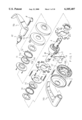
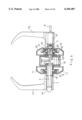
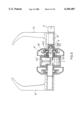
- FIG. 1 is an exploded view of the main part of the lock assembly in accordance with the present invention and the two handles;
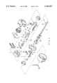
- FIG. 2 is an exploded view of the main part of the lock assembly in accordance with the present invention.
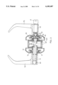
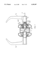
- FIG. 3 is a side elevational view, partly in section, of the lock assembly in accordance with the present invention when the lock assembly is locked by pushing the lock button into the inner handle;
- FIG. 4 is a side elevational view, partly in section, of the lock assembly in accordance with the present invention when the lock assembly is unlocked;
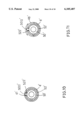
- FIG. 5 is an illustrative view to show the protrusion of the driving disk is moved in the transverse portion of the cruciform groove in the first driving tube;
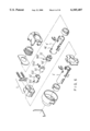
- FIG. 6 is an exploded view to show another embodiment of the main part of the lock assembly in accordance with the present invention.
- FIG. 7 is a side elevational view, partly in section, of the lock assembly as shown in FIG. 6, wherein the lock assembly is unlocked;
- FIG. 8 is a side elevational view, partly in section, of the lock assembly as shown in FIG. 6, wherein the lock assembly is locked;
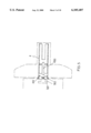
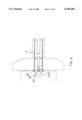
- FIG. 9 is an illustrative view to illustrate the movement of the guiding member in the radial slot and the longitudinal slot in the tube;
- FIG. 10 is an end cross sectional view to show the guiding member received in the slit in the outer tube.
- FIG. 11 is an end cross sectional view to show the guiding member received in the radial slot.
- the lock assembly in accordance with the present invention comprises an outer handle 7b with a tumbler cylinder 42 received therein and an inner handle 7a, and a retractor 2 connected between the inner handle 7a and the outer handle 7b wherein a latch bolt 9 is retractably received in the retractor 2.
- a tube 4 is connected to the outer handle 7b and has a cruciform groove 43 defined through the wall thereof, the cruciform groove 43 including a longitudinal portion 430 and a transverse portion 431 as shown in FIG. 5.
- a first driving block 40 and an engaging boss 45 respectively extend radially outward from the tube 4.
- a first driving tube 50 is rotatably received in the tube 4 and has two first slots 53 and two second slots 56 respectively defined through the wall thereof.
- a connecting disk 52 is movably received in the first driving tube 50 and has two protrusions 522 extending therefrom which are movably received in the two second slots 56.
- the connecting disk 52 is fixedly connected to the tumbler cylinder 42.
- Two second driving blocks 510 extend radially outward from the first driving tube 50 and a driving disk 55 is movably received in the first driving tube 50, the driving disk 55 having two protrusions 552 extending therefrom and received in the two first slots 53.
- the inner handle 7a has a second driving tube 3 received therein and an actuating plate 6 extends through the second driving tube 3.
- the actuating plate 6 has a lock button 60 connected to the first end thereof and the lock button 60 is exposed from the inner handle 7a.
- the second end of the actuating plate 6 has a first lug 61 and a second lug 62 respectively extending laterally therefrom, and the second end of the actuating plate 6 is fixedly connected to the driving disk 55.
- a spring 54 is biased between the driving disk 55 and the connecting disk 52.
- the latch bolt 9 retractably received in the retractor 2 is moved by the rotation of the first driving block 40 and the second driving block 510 as the conventional mechanism known to the persons in the art.
- a second driving tube 3 is connected to the inner handle 7a and the actuating plate 6 extends through the driving tube 3.
- a third driving block 30 extend radially from the second driving tube 3 and is engaged with the retractor 2.
- Each of the inner handle 7a and the outer handle 7b has a torsion spring 73 connected thereto, wherein the torsion spring 73 mounted to the driving tube 3 has one end thereof engaged with a lug 712 of a cap member 71' and the torsion spring 73 mounted to the tube 4 has one end thereof engaged with a lug 712 of a cap member 71.
- the other end of the torsion spring 73 is engaged with the rib 720 of each of the two positioning rings 72, 72' so that the inner handle 7a and the outer handle 7b will return to their original position when releasing them.
- Each of the cap members 71, 71' has a central hole defined centrally therethrough and two notches 713, 714 are defined in the periphery defining the central hole.
- the tube 4 has an engaging boss 45 and a stop pin 33 respectively extending radially outward therefrom and the second driving tube 3 having an engaging boss 36 and another stop pin 33' extending radially outward therefrom so that the two engaging bosses 45, 36 are respectively engaged with the two respective notches 714 of the cap members 71, and the two stop pins 33, 33' are respectively engaged with the two notches 713 of the two cap members 71, 71'.
- the protrusion 552 of the driving disk 55 can be moved within the transverse portion 431 of the cruciform groove 43 so that even if the inner handle 7a or the outer handle 7b is rotated by a large angle, there is a large enough space for the protrusion 552 to move.
- FIG. 6 and 7 show another embodiment of the lock assembly of the present invention, wherein the tube 4' is connected to the tumbler cylinder 42' and the outer handle 7b.
- a retaining tube 51' is received in the tube 4' and has a spiral groove 511' defined through the wall thereof.
- a first driving tube 50' is movably received in the retaining tube 51'.
- a pin 502' extends through the spiral groove 511' and connected to the first driving tube 50' which is co-rotated with the tumbler cylinder 42'.
- a guiding member 5011' is connected to the first driving tube 50'.
- the tube 4' has a circumferential slot 46' which communicates with a longitudinal slot 41' so that the guiding member 5011' is movably received in the circumferential slot 46'.
- An outer tube 52' is mounted to the retaining tube 51' and has a slit 522' which communicates with the longitudinal slot 41' in the tube 4'.
- the second driving tube 3' is connected to the inner handle 7a with the retractor 2 connected between the second driving tube 3' and the tube 4' so that either of the inner handle 7a or the outer handle 7b is rotated, the latch bolt (not shown) is retracted by a known manner.
- the guiding member 5011' is located in the slit 522' so that when rotating the outer handle 7b, the outer tube 52' is rotated together with the guiding member 5011 ' and the latch bolt is retracted by the protrusion 521' on the outer tube 52'.
- the first driving tube 50' is moved in the retaining tube 51' by the pin 502' moved along the spiral groove 511' so that the first driving tube 50' is retracted in the retaining tube 51'.
- the guiding member 5011' is moved from the slit 522' and received in the slot 46' which extends radially through the wall of the tube 4' as shown in FIGS. 6 and 11.
- the guiding member 5011' is then freely rotatable within the circumferential slot 46'.
- the first driving tube 50' When unlocking the lock assembly by the key 8, the first driving tube 50' is rotated and moved away from the retaining tube 51' with the pin 502' moving along the spiral groove 511'.
- the guiding member 5011' is therefore moved to the slit 522' again so that when rotating the outer handle 7b, the outer tube 52' is rotated to retract the latch bolt.
Landscapes
- Steering Devices For Bicycles And Motorcycles (AREA)
Abstract
A lock assembly includes a tube received in an outer handle and a first driving tube is rotatably received in the tube. The tube has a cruciform groove defined through the wall thereof and a driving disk is movably received in the first driving tube has two slots with two protrusions of the driving disk extends through the two slots. An inner handle has an actuating plate extending therethrough which is fixedly connected to the driving disk so that when locking the lock assembly by pushing the lock button, one of the protrusions of the driving disk is moved to be received in the transverse portion of the cruciform groove so that the handles are allowed to rotate a larger rotational angle.
Description
This application is a divisional of copending application application Ser. No. 09/268,346 filed on Mar. 16, 1999.
The present invention relates to a lock assembly, and more particularly, to a lock assembly having a tube with a cruciform groove defined therethrough the wall thereof so that when the lock assembly is locked, the actuating disk is located in the transverse portion of the cruciform groove so that it can be freely rotated.
A conventional lock assembly generally includes an inner handle to which a lock button is received and an outer handle in which a tumbler cylinder is received. The lock button has an actuating plate to be connected to an actuating disk which is connected to a driving tube so that when rotating the inner handle, the driving tube is rotated by the rotation of the actuating disk to retract the latch bolt. The tumbler cylinder is connected to a second driving tube which is rotated when the outer handle is rotated and retract the latch bolt. It is to be noted that the parts in the lock assembly generally are small and have a thin wall so that if a user rotates the inner handle or the outer handle violently by a large rotation angle, these parts could be damaged and/or permanently deformed. The handle could be rotated by a large torque unintentionally and the internal parts of the lock assembly could be deformed.
The present invention intends to provide a lock assembly which allows the handles thereof to be rotated by a large angle without damaging the parts in the lock assembly when the lock assembly is in a locked position.
The lock assembly has a tube having cruciform groove defined through the wall thereof so that the actuating disk is rotatably received in the transverse portion of the cruciform groove such that when the handles are rotated by a large angle, the actuating disk can be rotated within the transverse portion of the cruciform groove.
In accordance with one aspect of the present invention, there is provided a lock assembly comprising an outer handle with a tumbler cylinder received therein and a inner handle, a retractor with a latch bolt is connected between the inner handle and the outer handle. A tube has a cruciform groove defined through the wall thereof and is connected to the outer handle. A first driving block extends radially outward therefrom. A first driving tube is rotatably received in the tube and co-rotatably connected to the tumbler cylinder. A second driving block extends radially outward therefrom. The first driving tube has two first slots defined through the wall thereof and a driving disk is movably received in the first driving tube, wherein the driving disk has two protrusions extending therefrom and received in the two first slots.
The inner handle has a second driving tube received therein and an actuating plate extends through the second driving tube. A lock button is connected to the first end of the actuating plate and the second end of the actuating plate has a first lug and a second lug respectively extending laterally therefrom. The second end of the actuating plate is fixedly connected to the driving disk. The latch bolt is engaged with the first driving block and the second driving block.
A second driving tube is connected to the inner handle and the actuating plate extends through the driving tube. A third driving block extends radially from the second driving tube and is engaged with the retractor. When the lock assembly is locked by pushing the lock button, one of the protrusions of the driving disk is moved to be located in the transverse portion of the cruciform groove.
The object of the present invention is to provide a lock assembly which allows the handles thereof to be rotated by a large rotational angle without damaging the parts in the lock assembly.
Further objects, advantages, and features of the present invention will become apparent from the following detailed description with appropriate reference to the accompanying drawings.
FIG. 1 is an exploded view of the main part of the lock assembly in accordance with the present invention and the two handles;
FIG. 2 is an exploded view of the main part of the lock assembly in accordance with the present invention;
FIG. 3 is a side elevational view, partly in section, of the lock assembly in accordance with the present invention when the lock assembly is locked by pushing the lock button into the inner handle;
FIG. 4 is a side elevational view, partly in section, of the lock assembly in accordance with the present invention when the lock assembly is unlocked;
FIG. 5 is an illustrative view to show the protrusion of the driving disk is moved in the transverse portion of the cruciform groove in the first driving tube;
FIG. 6 is an exploded view to show another embodiment of the main part of the lock assembly in accordance with the present invention;
FIG. 7 is a side elevational view, partly in section, of the lock assembly as shown in FIG. 6, wherein the lock assembly is unlocked;
FIG. 8 is a side elevational view, partly in section, of the lock assembly as shown in FIG. 6, wherein the lock assembly is locked;
FIG. 9 is an illustrative view to illustrate the movement of the guiding member in the radial slot and the longitudinal slot in the tube;
FIG. 10 is an end cross sectional view to show the guiding member received in the slit in the outer tube, and
FIG. 11 is an end cross sectional view to show the guiding member received in the radial slot.
Referring to FIGS. 1 to 3, the lock assembly in accordance with the present invention comprises an outer handle 7b with a tumbler cylinder 42 received therein and an inner handle 7a, and a retractor 2 connected between the inner handle 7a and the outer handle 7b wherein a latch bolt 9 is retractably received in the retractor 2. A tube 4 is connected to the outer handle 7b and has a cruciform groove 43 defined through the wall thereof, the cruciform groove 43 including a longitudinal portion 430 and a transverse portion 431 as shown in FIG. 5. A first driving block 40 and an engaging boss 45 respectively extend radially outward from the tube 4. A first driving tube 50 is rotatably received in the tube 4 and has two first slots 53 and two second slots 56 respectively defined through the wall thereof. A connecting disk 52 is movably received in the first driving tube 50 and has two protrusions 522 extending therefrom which are movably received in the two second slots 56. The connecting disk 52 is fixedly connected to the tumbler cylinder 42. Two second driving blocks 510 extend radially outward from the first driving tube 50 and a driving disk 55 is movably received in the first driving tube 50, the driving disk 55 having two protrusions 552 extending therefrom and received in the two first slots 53.
The inner handle 7a has a second driving tube 3 received therein and an actuating plate 6 extends through the second driving tube 3. The actuating plate 6 has a lock button 60 connected to the first end thereof and the lock button 60 is exposed from the inner handle 7a. The second end of the actuating plate 6 has a first lug 61 and a second lug 62 respectively extending laterally therefrom, and the second end of the actuating plate 6 is fixedly connected to the driving disk 55. A spring 54 is biased between the driving disk 55 and the connecting disk 52. The latch bolt 9 retractably received in the retractor 2 is moved by the rotation of the first driving block 40 and the second driving block 510 as the conventional mechanism known to the persons in the art.
A second driving tube 3 is connected to the inner handle 7a and the actuating plate 6 extends through the driving tube 3. A third driving block 30 extend radially from the second driving tube 3 and is engaged with the retractor 2. When the lock assembly is locked by pushing the lock button 60 as shown in FIG. 3, the protrusions 552 of the driving disk 55 are moved to be located in the transverse portion 431 of the cruciform groove 43. As shown in FIG. 4, when unlocking the lock assembly either by using the key 8 rotating the tumbler cylinder 42 or rotating the inner handle 7a, the protrusion 552 can be rotated within the transverse portion 431 of the cruciform groove 43 so that even if the operator rotates the outer handle 7b by a large rotational angle, no parts in the lock assembly will be deformed or damaged.
Each of the inner handle 7a and the outer handle 7b has a torsion spring 73 connected thereto, wherein the torsion spring 73 mounted to the driving tube 3 has one end thereof engaged with a lug 712 of a cap member 71' and the torsion spring 73 mounted to the tube 4 has one end thereof engaged with a lug 712 of a cap member 71. The other end of the torsion spring 73 is engaged with the rib 720 of each of the two positioning rings 72, 72' so that the inner handle 7a and the outer handle 7b will return to their original position when releasing them.
Each of the cap members 71, 71' has a central hole defined centrally therethrough and two notches 713, 714 are defined in the periphery defining the central hole. The tube 4 has an engaging boss 45 and a stop pin 33 respectively extending radially outward therefrom and the second driving tube 3 having an engaging boss 36 and another stop pin 33' extending radially outward therefrom so that the two engaging bosses 45, 36 are respectively engaged with the two respective notches 714 of the cap members 71, and the two stop pins 33, 33' are respectively engaged with the two notches 713 of the two cap members 71, 71'.
Accordingly, because of the cruciform groove 43 in the tube 4, the protrusion 552 of the driving disk 55 can be moved within the transverse portion 431 of the cruciform groove 43 so that even if the inner handle 7a or the outer handle 7b is rotated by a large angle, there is a large enough space for the protrusion 552 to move.
FIG. 6 and 7 show another embodiment of the lock assembly of the present invention, wherein the tube 4' is connected to the tumbler cylinder 42' and the outer handle 7b. A retaining tube 51' is received in the tube 4' and has a spiral groove 511' defined through the wall thereof. A first driving tube 50' is movably received in the retaining tube 51'. A pin 502' extends through the spiral groove 511' and connected to the first driving tube 50' which is co-rotated with the tumbler cylinder 42'. A guiding member 5011' is connected to the first driving tube 50'. The tube 4' has a circumferential slot 46' which communicates with a longitudinal slot 41' so that the guiding member 5011' is movably received in the circumferential slot 46'. An outer tube 52' is mounted to the retaining tube 51' and has a slit 522' which communicates with the longitudinal slot 41' in the tube 4'.
The second driving tube 3' is connected to the inner handle 7a with the retractor 2 connected between the second driving tube 3' and the tube 4' so that either of the inner handle 7a or the outer handle 7b is rotated, the latch bolt (not shown) is retracted by a known manner. Further referring to FIG. 10, when the lock assembly is in an opened position, the guiding member 5011' is located in the slit 522' so that when rotating the outer handle 7b, the outer tube 52' is rotated together with the guiding member 5011 ' and the latch bolt is retracted by the protrusion 521' on the outer tube 52'.
Referring to FIGS. 8, 9 and 11 when the lock assembly is locked by rotating a key 8 to rotate the first driving tube 50', the first driving tube 50' is moved in the retaining tube 51' by the pin 502' moved along the spiral groove 511' so that the first driving tube 50' is retracted in the retaining tube 51'. In the meanwhile, the guiding member 5011' is moved from the slit 522' and received in the slot 46' which extends radially through the wall of the tube 4' as shown in FIGS. 6 and 11. The guiding member 5011' is then freely rotatable within the circumferential slot 46'. In other words, when the lock assembly is locked, even if the outer handle 7b is unintentionally rotated, no internal parts of the lock assembly will be damaged.
When unlocking the lock assembly by the key 8, the first driving tube 50' is rotated and moved away from the retaining tube 51' with the pin 502' moving along the spiral groove 511'. The guiding member 5011' is therefore moved to the slit 522' again so that when rotating the outer handle 7b, the outer tube 52' is rotated to retract the latch bolt.
The invention is not limited to the above embodiment but various modification thereof may be made. It will be understood by those skilled in the art that various changes in form and detail may made without departing from the scope and spirit of the present invention.
Claims (1)
1. A lock assembly comprising:
an outer handle with a tumbler cylinder received therein, a tube having a circumferential slot and a longitudinal slot defined through the wall thereof, said circumferential slot communicating with said longitudinal slot;
a retaining tube received in said tube and having a spiral groove defined through the wall thereof, a driving tube movably received in said retaining tube and connected to said tumbler cylinder, a pin extending through said spiral groove and connected to said first tube, an outer tube mounted to said retaining tube and having a slit defined longitudinally through the wall thereof, said slit communicating with said longitudinal slot of said tube, a guiding member extending from said driving tube and movably received in said circumferential slot when said lock assembly is locked and in said slit when said lock assembly is unlocked, and
an inner handle connected to an inner driving tube and a retractor connected between said tube connected to said outer handle and said driving tube connected to said inner handle, a latch bolt retractably received in said retractor and retractable by said tube and said inner driving tube.
Priority Applications (1)
| Application Number | Priority Date | Filing Date | Title |
|---|---|---|---|
| US09/497,101 US6105407A (en) | 1999-03-16 | 2000-02-03 | Lock assembly allowing the handles thereof rotated by a large angle |
Applications Claiming Priority (2)
| Application Number | Priority Date | Filing Date | Title |
|---|---|---|---|
| US09/268,346 US6085561A (en) | 1999-03-16 | 1999-03-16 | Lock assembly allowing the handles thereof rotated by a large angle |
| US09/497,101 US6105407A (en) | 1999-03-16 | 2000-02-03 | Lock assembly allowing the handles thereof rotated by a large angle |
Related Parent Applications (1)
| Application Number | Title | Priority Date | Filing Date |
|---|---|---|---|
| US09/268,346 Division US6085561A (en) | 1999-03-16 | 1999-03-16 | Lock assembly allowing the handles thereof rotated by a large angle |
Publications (1)
| Publication Number | Publication Date |
|---|---|
| US6105407A true US6105407A (en) | 2000-08-22 |
Family
ID=23022568
Family Applications (2)
| Application Number | Title | Priority Date | Filing Date |
|---|---|---|---|
| US09/268,346 Expired - Fee Related US6085561A (en) | 1999-03-16 | 1999-03-16 | Lock assembly allowing the handles thereof rotated by a large angle |
| US09/497,101 Expired - Fee Related US6105407A (en) | 1999-03-16 | 2000-02-03 | Lock assembly allowing the handles thereof rotated by a large angle |
Family Applications Before (1)
| Application Number | Title | Priority Date | Filing Date |
|---|---|---|---|
| US09/268,346 Expired - Fee Related US6085561A (en) | 1999-03-16 | 1999-03-16 | Lock assembly allowing the handles thereof rotated by a large angle |
Country Status (1)
| Country | Link |
|---|---|
| US (2) | US6085561A (en) |
Cited By (8)
| Publication number | Priority date | Publication date | Assignee | Title |
|---|---|---|---|---|
| US6386602B1 (en) * | 2000-10-26 | 2002-05-14 | Tawain Fu Hsing Industrial Co., Ltd. | Lever handle structure for lock |
| US6575006B1 (en) * | 2001-05-14 | 2003-06-10 | Tung Lung Metal Industry Co., Ltd. | Lock |
| US20040144143A1 (en) * | 2002-07-29 | 2004-07-29 | Tung Lung Metal Industry Co., Ltd. | Lock engaging-and-disengaging mechanism |
| US20070051144A1 (en) * | 2005-09-07 | 2007-03-08 | Lien-Hsi Huang | Rotation pipe of handle |
| US20070180874A1 (en) * | 2006-02-08 | 2007-08-09 | Chien-Chung Wang | Door lock with button stopper |
| US20090008949A1 (en) * | 2007-07-05 | 2009-01-08 | Thase Enterprise Co., Ltd. | Door Handle Apparatus |
| US20120267903A1 (en) * | 2011-04-22 | 2012-10-25 | Welsby Scott D | Clutch mechanism for a lock assembly |
| CN103938924A (en) * | 2013-01-23 | 2014-07-23 | 何华明 | Dark box type technical-unlocking-resistant machine |
Families Citing this family (9)
| Publication number | Priority date | Publication date | Assignee | Title |
|---|---|---|---|---|
| US6357270B1 (en) * | 1999-09-08 | 2002-03-19 | Scovill Locks, S.A. De C.V. | Free-wheeling door lock mechanism |
| US6615630B2 (en) * | 2000-12-05 | 2003-09-09 | Tong-Lung Metal Industry Co., Ltd. | Door lock |
| US6497126B2 (en) * | 2001-02-06 | 2002-12-24 | Taiwan Fu Hsing Industrial Co., Ltd. | Outer handle structure of a lock which may be idle |
| TW484648U (en) * | 2001-05-02 | 2002-04-21 | Taiwan Fu Hsing Ind Co Ltd | Auto-locking lock |
| US6742367B2 (en) * | 2002-08-19 | 2004-06-01 | Taiwan Fu Hsing Industrial Co., Ltd | Inside locking device of flat handle lock |
| TW590137U (en) * | 2003-04-09 | 2004-06-01 | Tong Lung Metal Ind Co Ltd | Intensifying structure used in horizontal handle |
| US20050029820A1 (en) * | 2003-08-04 | 2005-02-10 | Mannella Eugenio G. | Handle set including a spindle assembly configured to resist removal |
| US7559219B2 (en) * | 2007-06-29 | 2009-07-14 | Jeff Chen | Door lock |
| AU2009262843B2 (en) * | 2008-06-27 | 2014-07-31 | Schlage Lock Company | Electronic door lock with modular components |
Citations (13)
| Publication number | Priority date | Publication date | Assignee | Title |
|---|---|---|---|---|
| US148785A (en) * | 1874-03-17 | Improvement in knob-latches | ||
| US626340A (en) * | 1899-06-06 | The nmris f ctcrs co | ||
| FR12097E (en) * | 1908-12-16 | 1910-07-05 | Jules Henri Soin | Locking button for all locks |
| DE600389C (en) * | 1931-12-20 | 1934-07-21 | Huelsbeck & Fuerst | Securing locks on vehicle doors |
| US4920773A (en) * | 1988-02-08 | 1990-05-01 | Yale Security Inc. | Door lock having disengages outer lever handle when in the locked condition and means to bias the handle toward horizontal position |
| US5125696A (en) * | 1990-10-12 | 1992-06-30 | Emhart Inc. | Cylindrical lock assembly |
| US5177987A (en) * | 1991-07-12 | 1993-01-12 | Shen Chao C | Key-in-lever type door lock used for handicapped people |
| US5598726A (en) * | 1996-03-29 | 1997-02-04 | Schlage Lock Company | Privacy lockset for a door |
| US5784909A (en) * | 1997-04-22 | 1998-07-28 | Taiwan Fu Hsing Industry Co., Ltd. | Control mechanism for tubular locks |
| US5794472A (en) * | 1995-05-01 | 1998-08-18 | Best Lock Corporation | Disconnecting drive mechanism for cylindrical lockset |
| US5809815A (en) * | 1996-08-29 | 1998-09-22 | Taiwan Fu Hsing | Lever lock assembly with a burglar-proof exterior handle |
| US5868018A (en) * | 1996-08-26 | 1999-02-09 | Hyundae Metal Co., Ltd. | Door lock |
| US5934117A (en) * | 1997-09-24 | 1999-08-10 | Shen; Mu-Lin | Lock with a clutching outer handle |
-
1999
- 1999-03-16 US US09/268,346 patent/US6085561A/en not_active Expired - Fee Related
-
2000
- 2000-02-03 US US09/497,101 patent/US6105407A/en not_active Expired - Fee Related
Patent Citations (14)
| Publication number | Priority date | Publication date | Assignee | Title |
|---|---|---|---|---|
| US626340A (en) * | 1899-06-06 | The nmris f ctcrs co | ||
| US148785A (en) * | 1874-03-17 | Improvement in knob-latches | ||
| FR12097E (en) * | 1908-12-16 | 1910-07-05 | Jules Henri Soin | Locking button for all locks |
| DE600389C (en) * | 1931-12-20 | 1934-07-21 | Huelsbeck & Fuerst | Securing locks on vehicle doors |
| US4920773B1 (en) * | 1988-02-08 | 1997-01-14 | Yale Security Inc | Door lock having disengaged outer lever handle when in the locked condition and means to bias the hadle toward horizontal position |
| US4920773A (en) * | 1988-02-08 | 1990-05-01 | Yale Security Inc. | Door lock having disengages outer lever handle when in the locked condition and means to bias the handle toward horizontal position |
| US5125696A (en) * | 1990-10-12 | 1992-06-30 | Emhart Inc. | Cylindrical lock assembly |
| US5177987A (en) * | 1991-07-12 | 1993-01-12 | Shen Chao C | Key-in-lever type door lock used for handicapped people |
| US5794472A (en) * | 1995-05-01 | 1998-08-18 | Best Lock Corporation | Disconnecting drive mechanism for cylindrical lockset |
| US5598726A (en) * | 1996-03-29 | 1997-02-04 | Schlage Lock Company | Privacy lockset for a door |
| US5868018A (en) * | 1996-08-26 | 1999-02-09 | Hyundae Metal Co., Ltd. | Door lock |
| US5809815A (en) * | 1996-08-29 | 1998-09-22 | Taiwan Fu Hsing | Lever lock assembly with a burglar-proof exterior handle |
| US5784909A (en) * | 1997-04-22 | 1998-07-28 | Taiwan Fu Hsing Industry Co., Ltd. | Control mechanism for tubular locks |
| US5934117A (en) * | 1997-09-24 | 1999-08-10 | Shen; Mu-Lin | Lock with a clutching outer handle |
Cited By (11)
| Publication number | Priority date | Publication date | Assignee | Title |
|---|---|---|---|---|
| US6386602B1 (en) * | 2000-10-26 | 2002-05-14 | Tawain Fu Hsing Industrial Co., Ltd. | Lever handle structure for lock |
| US6575006B1 (en) * | 2001-05-14 | 2003-06-10 | Tung Lung Metal Industry Co., Ltd. | Lock |
| US20040144143A1 (en) * | 2002-07-29 | 2004-07-29 | Tung Lung Metal Industry Co., Ltd. | Lock engaging-and-disengaging mechanism |
| US6935148B2 (en) * | 2002-07-29 | 2005-08-30 | Tung Lung Metal Industry Co., Ltd. | Lock engaging-and-disengaging mechanism |
| US20070051144A1 (en) * | 2005-09-07 | 2007-03-08 | Lien-Hsi Huang | Rotation pipe of handle |
| US20070180874A1 (en) * | 2006-02-08 | 2007-08-09 | Chien-Chung Wang | Door lock with button stopper |
| US7377143B2 (en) * | 2006-02-08 | 2008-05-27 | Chien-Chung Wang | Door lock with button stopper |
| US20090008949A1 (en) * | 2007-07-05 | 2009-01-08 | Thase Enterprise Co., Ltd. | Door Handle Apparatus |
| US20120267903A1 (en) * | 2011-04-22 | 2012-10-25 | Welsby Scott D | Clutch mechanism for a lock assembly |
| US8939477B2 (en) * | 2011-04-22 | 2015-01-27 | Schlage Lock Company | Clutch mechanism for a lock assembly |
| CN103938924A (en) * | 2013-01-23 | 2014-07-23 | 何华明 | Dark box type technical-unlocking-resistant machine |
Also Published As
| Publication number | Publication date |
|---|---|
| US6085561A (en) | 2000-07-11 |
Similar Documents
| Publication | Publication Date | Title |
|---|---|---|
| US6105407A (en) | Lock assembly allowing the handles thereof rotated by a large angle | |
| US7100407B2 (en) | Handled lock set for a door | |
| US7213425B2 (en) | Padlock having dual unlocking modes | |
| US6351976B1 (en) | Door lock assembly | |
| US6598434B2 (en) | Dual mechanism lock | |
| US6041630A (en) | Clutch mechanism for a lock | |
| US6764112B2 (en) | Auxiliary lock with an adjustable backset | |
| US6216500B1 (en) | Device for unlocking tubular-type door lock in conjunction with indoor handle | |
| US5941108A (en) | Push button for a tubular lock unlockable by an inside handle thereof | |
| US5372025A (en) | Outer handle of a door lock | |
| US5784909A (en) | Control mechanism for tubular locks | |
| US6904775B2 (en) | Cuff lock and push-button locking mechanism | |
| US4689976A (en) | Pop-up handle assembly | |
| US6793254B1 (en) | Automatic door latch | |
| US6185966B1 (en) | Lock apparatus | |
| US6705138B1 (en) | Clutch mechanism for a lock | |
| US11156021B2 (en) | Multifunction hub core for mortise lock and method of assembly | |
| US4380915A (en) | Latch having a removable lock | |
| JP2003500574A (en) | Door lock device | |
| IE86904B1 (en) | Lock cylinder | |
| KR100297034B1 (en) | Lockset | |
| US6014878A (en) | Lock with a freely rotatable outside handle | |
| JP3017276B2 (en) | Cylinder lock | |
| US4194379A (en) | Pick-proof lock | |
| JPS5829710Y2 (en) | lock |
Legal Events
| Date | Code | Title | Description |
|---|---|---|---|
| AS | Assignment |
Owner name: SHYANG FENG ELECTRIC & MACHINERY CO., LTD., TAIWAN Free format text: ASSIGNMENT OF ASSIGNORS INTEREST;ASSIGNOR:YAO, CELINA;REEL/FRAME:010548/0263 Effective date: 19991116 |
|
| REMI | Maintenance fee reminder mailed | ||
| LAPS | Lapse for failure to pay maintenance fees | ||
| FP | Expired due to failure to pay maintenance fee |
Effective date: 20040822 |
|
| STCH | Information on status: patent discontinuation |
Free format text: PATENT EXPIRED DUE TO NONPAYMENT OF MAINTENANCE FEES UNDER 37 CFR 1.362 |