US6104896A - Apparatus and method for forming an interference fit - Google Patents
Apparatus and method for forming an interference fit Download PDFInfo
- Publication number
- US6104896A US6104896A US09/354,812 US35481299A US6104896A US 6104896 A US6104896 A US 6104896A US 35481299 A US35481299 A US 35481299A US 6104896 A US6104896 A US 6104896A
- Authority
- US
- United States
- Prior art keywords
- flange
- hollow cylindrical
- cylindrical member
- force
- interference fit
- Prior art date
- Legal status (The legal status is an assumption and is not a legal conclusion. Google has not performed a legal analysis and makes no representation as to the accuracy of the status listed.)
- Expired - Lifetime
Links
- 238000000034 method Methods 0.000 title claims description 24
- 238000006073 displacement reaction Methods 0.000 claims abstract description 17
- 108091008695 photoreceptors Proteins 0.000 claims description 102
- 239000000853 adhesive Substances 0.000 claims description 17
- 230000001070 adhesive effect Effects 0.000 claims description 17
- 239000004033 plastic Substances 0.000 claims description 10
- 229920003023 plastic Polymers 0.000 claims description 10
- 229910052751 metal Inorganic materials 0.000 claims description 9
- 239000002184 metal Substances 0.000 claims description 9
- 239000004020 conductor Substances 0.000 claims description 3
- 238000003780 insertion Methods 0.000 abstract description 11
- 230000037431 insertion Effects 0.000 abstract description 11
- 239000000463 material Substances 0.000 description 19
- 239000000758 substrate Substances 0.000 description 9
- 238000003384 imaging method Methods 0.000 description 7
- 230000008569 process Effects 0.000 description 7
- 239000002131 composite material Substances 0.000 description 6
- 230000006378 damage Effects 0.000 description 4
- -1 polytetrafluoroethylene Polymers 0.000 description 4
- 238000007600 charging Methods 0.000 description 3
- 238000000576 coating method Methods 0.000 description 3
- 238000012986 modification Methods 0.000 description 3
- 230000004048 modification Effects 0.000 description 3
- 239000002245 particle Substances 0.000 description 3
- 229920001343 polytetrafluoroethylene Polymers 0.000 description 3
- 239000004810 polytetrafluoroethylene Substances 0.000 description 3
- 238000004064 recycling Methods 0.000 description 3
- BFKJFAAPBSQJPD-UHFFFAOYSA-N tetrafluoroethene Chemical group FC(F)=C(F)F BFKJFAAPBSQJPD-UHFFFAOYSA-N 0.000 description 3
- 238000012546 transfer Methods 0.000 description 3
- OKTJSMMVPCPJKN-UHFFFAOYSA-N Carbon Chemical compound [C] OKTJSMMVPCPJKN-UHFFFAOYSA-N 0.000 description 2
- 239000004812 Fluorinated ethylene propylene Substances 0.000 description 2
- 230000002411 adverse Effects 0.000 description 2
- 229910052799 carbon Inorganic materials 0.000 description 2
- 238000004140 cleaning Methods 0.000 description 2
- 230000006835 compression Effects 0.000 description 2
- 238000007906 compression Methods 0.000 description 2
- 229920000840 ethylene tetrafluoroethylene copolymer Polymers 0.000 description 2
- 239000000203 mixture Substances 0.000 description 2
- 229920009441 perflouroethylene propylene Polymers 0.000 description 2
- 229920000515 polycarbonate Polymers 0.000 description 2
- 239000004417 polycarbonate Substances 0.000 description 2
- 239000011347 resin Substances 0.000 description 2
- 229920005989 resin Polymers 0.000 description 2
- 229920007925 Ethylene chlorotrifluoroethylene (ECTFE) Polymers 0.000 description 1
- 229920001774 Perfluoroether Polymers 0.000 description 1
- 229910052782 aluminium Inorganic materials 0.000 description 1
- XAGFODPZIPBFFR-UHFFFAOYSA-N aluminium Chemical compound [Al] XAGFODPZIPBFFR-UHFFFAOYSA-N 0.000 description 1
- 239000011230 binding agent Substances 0.000 description 1
- 230000008859 change Effects 0.000 description 1
- 239000011248 coating agent Substances 0.000 description 1
- 229920001940 conductive polymer Polymers 0.000 description 1
- 230000002950 deficient Effects 0.000 description 1
- 238000013461 design Methods 0.000 description 1
- 238000003618 dip coating Methods 0.000 description 1
- 230000000694 effects Effects 0.000 description 1
- 238000007786 electrostatic charging Methods 0.000 description 1
- 238000005421 electrostatic potential Methods 0.000 description 1
- 229920006351 engineering plastic Polymers 0.000 description 1
- 239000011521 glass Substances 0.000 description 1
- 238000001746 injection moulding Methods 0.000 description 1
- 238000009434 installation Methods 0.000 description 1
- 238000003754 machining Methods 0.000 description 1
- 238000004519 manufacturing process Methods 0.000 description 1
- 230000013011 mating Effects 0.000 description 1
- 238000005259 measurement Methods 0.000 description 1
- 239000000049 pigment Substances 0.000 description 1
- 229920000642 polymer Polymers 0.000 description 1
- 238000007639 printing Methods 0.000 description 1
- 238000003908 quality control method Methods 0.000 description 1
- 238000010107 reaction injection moulding Methods 0.000 description 1
- 230000008439 repair process Effects 0.000 description 1
- 238000006748 scratching Methods 0.000 description 1
- 230000002393 scratching effect Effects 0.000 description 1
- 238000004513 sizing Methods 0.000 description 1
- 229920001187 thermosetting polymer Polymers 0.000 description 1
Images


Classifications
-
- G—PHYSICS
- G03—PHOTOGRAPHY; CINEMATOGRAPHY; ANALOGOUS TECHNIQUES USING WAVES OTHER THAN OPTICAL WAVES; ELECTROGRAPHY; HOLOGRAPHY
- G03G—ELECTROGRAPHY; ELECTROPHOTOGRAPHY; MAGNETOGRAPHY
- G03G15/00—Apparatus for electrographic processes using a charge pattern
- G03G15/75—Details relating to xerographic drum, band or plate, e.g. replacing, testing
- G03G15/751—Details relating to xerographic drum, band or plate, e.g. replacing, testing relating to drum
-
- Y—GENERAL TAGGING OF NEW TECHNOLOGICAL DEVELOPMENTS; GENERAL TAGGING OF CROSS-SECTIONAL TECHNOLOGIES SPANNING OVER SEVERAL SECTIONS OF THE IPC; TECHNICAL SUBJECTS COVERED BY FORMER USPC CROSS-REFERENCE ART COLLECTIONS [XRACs] AND DIGESTS
- Y10—TECHNICAL SUBJECTS COVERED BY FORMER USPC
- Y10T—TECHNICAL SUBJECTS COVERED BY FORMER US CLASSIFICATION
- Y10T29/00—Metal working
- Y10T29/49—Method of mechanical manufacture
- Y10T29/49544—Roller making
- Y10T29/49547—Assembling preformed components
- Y10T29/49556—Work contacting surface element assembled to end support members
-
- Y—GENERAL TAGGING OF NEW TECHNOLOGICAL DEVELOPMENTS; GENERAL TAGGING OF CROSS-SECTIONAL TECHNOLOGIES SPANNING OVER SEVERAL SECTIONS OF THE IPC; TECHNICAL SUBJECTS COVERED BY FORMER USPC CROSS-REFERENCE ART COLLECTIONS [XRACs] AND DIGESTS
- Y10—TECHNICAL SUBJECTS COVERED BY FORMER USPC
- Y10T—TECHNICAL SUBJECTS COVERED BY FORMER US CLASSIFICATION
- Y10T29/00—Metal working
- Y10T29/49—Method of mechanical manufacture
- Y10T29/49764—Method of mechanical manufacture with testing or indicating
- Y10T29/49771—Quantitative measuring or gauging
- Y10T29/49776—Pressure, force, or weight determining
-
- Y—GENERAL TAGGING OF NEW TECHNOLOGICAL DEVELOPMENTS; GENERAL TAGGING OF CROSS-SECTIONAL TECHNOLOGIES SPANNING OVER SEVERAL SECTIONS OF THE IPC; TECHNICAL SUBJECTS COVERED BY FORMER USPC CROSS-REFERENCE ART COLLECTIONS [XRACs] AND DIGESTS
- Y10—TECHNICAL SUBJECTS COVERED BY FORMER USPC
- Y10T—TECHNICAL SUBJECTS COVERED BY FORMER US CLASSIFICATION
- Y10T29/00—Metal working
- Y10T29/53—Means to assemble or disassemble
- Y10T29/53039—Means to assemble or disassemble with control means energized in response to activator stimulated by condition sensor
- Y10T29/53061—Responsive to work or work-related machine element
- Y10T29/53078—Responsive to work or work-related machine element with means to fasten by frictional fitting
Definitions
- the xerographic imaging process begins by charging a photoconductive member to a uniform potential, and then exposing a light image of an original document onto the surface of the photoreceptor, either directly or via a digital image driven laser. Exposing the charged photoreceptor to light selectively discharges areas of the surface while allowing other areas to remain unchanged, thereby creating an electrostatic latent image of the document on the surface of the photoconductive member. A developer material is then brought into contact with the surface of the photoreceptor to transform the latent image into a visible reproduction. The developer typically includes toner particles with an electrical polarity opposite that of the photoconductive member. A blank copy sheet is brought into contact with the photoreceptor and the toner particles are transferred thereto by electrostatic charging the sheet.
- the sheet is subsequently heated, thereby permanently affixing the reproduced image to the sheet. This results in a "hard copy" reproduction of the document or image.
- the photoconductive member is then cleaned to remove any charge and/or residual developing material from its surface to prepare it for subsequent imaging cycles.
- Electrostatographic imaging members are well known in the art.
- One type of photoreceptor conventionally utilized for copiers and printers comprises a hollow electrically conductive drum substrate which has been dip coated with various coatings including at least one photoconductive coating comprising pigment particles dispersed in a film-forming binder.
- These photoreceptors are usually supported on an electrically conductive shaft by drum supporting hubs or end flanges.
- the hubs are usually constructed of plastic material and have a hole through their center into which a supporting axle shaft is inserted. Since hubs are usually constructed of electrically insulating plastic material, an electrical grounding means comprising a flexible spring metal strip is secured to the hub and positioned to contact both the electrically conductive axle shaft and the electrically conductive metal substrate of the photoreceptor drum.
- a drum supporting hub having a tapered pot-like hub configuration comprising a bottom section and a rim, the rim comprising a plurality of circumferentially spaced resilient fingers extending at a slight incline outwardly from the axis of the pot-like hub away from the bottom section, at least three of the fingers having lips at the ends of the fingers, the lips projecting away from the axis for engagement with an end of a cylindrical drum upon insertion of the pot-like hub into the drum, the rim other than the lips having an outside diameter slightly larger than the outside diameter of the bottom.
- the drum supporting hub is employed in a drum assembly comprising the hub, a cylindrical drum having a circular cross-section and a shaft positioned along the axis of the drum.
- the hub is plastic, which is made of or coated with an electrically conductive material to permit electrical grounding of the drum through a shaft passing through the hub.
- a metal shim is utilized to electrically ground the drum to the shaft.
- this metal ground shim is often bent out of alignment when inserted into one end of a photoreceptor drum. Such misalignment can result in the metal strip not contacting the interior of the drum or the axle or both after insertion of the hub into the end of the drum is completed. Further, coatings electrically insulating in the dark that are formed on the surface of the interior of the drum during dip coating can adversely affect electrical grounding of the drum to the electrically conductive drum axle shaft. If inadequate electrical grounding of the drum to the axle shaft is detected after the drum has been inserted into a modular replacement unit in which photoreceptor and various other subsystems such as cleaning and charging units are permanently mounted, repair of the drum is usually impossible without destruction of the module.
- a drum supporting hub comprising a disk shaped member having a circular periphery, a hole extending axially through the center of the disk shaped member, and at least one long thin electrically conductive resilient member secured to the disk shaped member, the resilient member having a central section adjacent the hole and having opposite ends, each of the ends terminating into at least one pointed tip adjacent the circular periphery of the disk shaped member, and the resilient member having a major plane substantially parallel to the axis of the disk shaped member.
- This hub may be inserted in at least one end of a cylindrical electrostatographic imaging member to produce an imaging member assembly. While this hub may adequately support the photoreceptor, the pointed tips can for m scratches and grooves in the interior surface of the drum during installation, use and removal. These scratches or grooves can adversely affect recycling of the cylindrical substrate.
- U.S. Pat. No. 5,630,196 to Swain issued May 13, 1997 discloses a hollow cylinder supporting end flange including a disk shaped member having a circular periphery and a coil spring having a major plane substantially parallel to the major plane of the disk shaped member.
- the coil spring also has an exposed arcuate outer periphery with a diameter larger than the inside diameter of the hollow cylinder, an outer exposed end and an inner end, with the inner end comprising a section secured to the end flange and the exposed arcuate outer periphery of the coil spring being adjacent the circular periphery of the disk shaped member for engagement with a hollow cylindrical member upon insertion of the coil spring into the hollow cylindrical member.
- the end flange may be utilized as a component of an assembly including a hollow cylindrical electrostatographic imaging member having a circular cross section and an inner surface, and an end flange secured to at least one end of the hollow cylindrical member by a partially wound coil spring, the spring having an inner end and an outer end, the inner end being secured to the end flange and the outer end having an exposed arcuate outer surface in frictional contact with the inner surface of the hollow cylindrical member.
- a process for fabricating this assembly is also disclosed.
- U.S. Pat. No. 5,599,265 to Foltz issued Feb. 4, 1997 discloses a hollow cylinder supporting end flange comprising a disk shaped member, a supporting hub extending axially from the disk shaped member and an annular ring supported on the hub, the ring comprising a plurality of sharp protrusions or barbs extending from the ring in a direction away from the hub for engagement with the hollow cylindrical member upon insertion of the annular ring into the hollow cylindrical member.
- This end flange is utilized in an assembly comprising a hollow cylindrical member having a circular cross section and an inner surface and an end flange comprising a disk shaped member having a circular periphery, a supporting hub extending axially from the disk shaped member into one end of the hollow cylindrical member and an annular ring supported on and secured to the hub, the ring comprising a plurality of sharp protrusions extending from the ring in a direction away from the hub into engagement with inner surface of the hollow cylindrical member to secure the hollow cylindrical member to the end flange.
- U.S. Pat. No. 4,400,077 to Kozuka et al. issued August 1983 discloses a photosensitive drum assembly for an electrostatic copying apparatus which includes a cylindrical drum with a photosensitive layer around its outer periphery. The drum is held between a pair of flanges at opposite axial ends of the drum. Each of the flanges is formed having a diameter larger than the external diameter of the drum. At the edge of each flange is a cylindrical portion extending along the axis of the drum to face toward the opposite flange. The end edges of the drum closely fit into the cylindrical portions.
- U.S. Pat. No. 4,120,576 to Babish issued Oct. 17, 1978 discloses a drum support apparatus including outboard and inboard hubs having outer surfaces and adapted for interface fitting with the inside surface of the drum.
- the hubs are supported on a shaft that is cantilevered from a frame and have recessed areas on central portions to cooperate with locking tabs located on a tubular member loosely fitted on the shaft.
- U.S. Pat. No. 5,402,207 to Michlin issued Mar. 28, 1995 teaches a conductive photoreceptor drum gear that may be made of metal.
- a conductive joining material is used to fix the bushing with respect to the photoreceptor, insuring electrical contact between the bushing and the photoreceptor.
- the bushing for the gear has prongs, the prongs dig into the inner wall of the photoreceptor and establish electrical contact with the photoreceptor.
- the knurls cut into the inner wall of the photoreceptor to establish electrical contact with the photoreceptor and a non-conductive joining material can be used to insure that the gear is fixed with respect to the photoreceptor.
- U.S. Pat. No. 5,634,175 to Michlin et al. issued May 27, 1997 teaches an electrical contact device for a developer roller in a toner cartridge.
- a developer roll contact device having a smooth flange which fits snugly inside the end of the developer roll and is used to establish electrical contact between the developer roller and the printer electrical contact.
- Developer roller contact device may be made of conductive plastic and may be fitted to the developer roller without adhesive.
- U.S. Pat. No. 5,815,773 to Zaman issued Sep. 29, 1998 discloses a composite photoreceptor flange with an end flange made from a composition which includes polycarbonate, polytetrafluoroethylene, and glass.
- the mounting of the end flange in the photoreceptor does not require the use of an adhesive material.
- a grounding plate is necessary in order to provide an electrical ground for the photoreceptor.
- U.S. Pat. No. 5,893,203 to Buttrick, Jr. issued Apr. 13, 1999 discloses a process for seating a tight-fitting headed fastener in a hole in a workpiece so that the head of the fastener contacts the workpiece.
- a fastener is inserted into a hole in the workpiece and a driver contacts the head of the fastener and senses and records the position of the fastener head to determine how far the fastener must be driven into the hole to seat the fastener head against the workpiece surface.
- an apparatus for forming an interference fit between a flange device which includes a flange, and a hollow cylindrical member having a first end and a second end.
- the apparatus includes a support for supporting the hollow cylindrical member so that the flange device may be located with respect to the first end of the hollow cylindrical member, a force member for applying a force to the flange device such that the flange is inserted into the hollow cylindrical member to form the interference fit, a displacement sensor for sensing the distance the flange is inserted into the hollow cylindrical member, a load sensor for sensing the force supplied by the force member; and an assembly indicator which uses sensor readings from the displacement sensor and the load sensor to determine whether the interference fit meets predetermined force and distance assembly specifications.
- the flange has a length, an inner diameter, and an outer diameter, such that the outer diameter of the flange is sized with respect to the inner surface of the hollow cylindrical member and the length of the flange is such that an interference fit is formed between the flange and the inner surface of the hollow cylindrical member, the interference fit being maintained in the absence of an adhesive.
- Another aspect of the invention is drawn to a method of forming an interference fit between the outer surface a flange, and an inner surface of a hollow cylindrical member having a first end and a second end.
- the method includes supporting the hollow cylindrical member so that the flange may be located with respect to the first end of the hollow cylindrical member; applying an assembly force with a force member to the flange such that the flange is inserted into the hollow cylindrical member to form the interference fit; sensing the distance the flange is inserted into the hollow cylindrical member with a displacement sensor; sensing the assembly force supplied by the force member with a load sensor; and determining whether the interference fit meets predetermined force and distance assembly specifications, wherein the flange has a length, an inner diameter, and an outer diameter, such that the outer diameter of the flange is sized with respect to the inner surface of the hollow cylindrical member and the length of the flange is such that an interference fit is formed between the flange and the inner surface of the hollow cylindrical member, the interference fit being maintained in the absence of an adhesive.
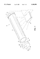
- FIG. 1 depicts a schematic, three dimensional view of the conductive flange device of the present invention as it is mounted to an electrostatographic photoreceptor.
- FIG. 2 depicts a front view of the conductive composite flange of the present invention.
- FIG. 3 depicts a rear view of the conductive composite flange of the present invention.
- FIG. 4 depicts a side view of the conductive composite flange device of the present invention.
- FIG. 5 depicts a front view of the flange device
- FIG. 6 depicts a schematic view of the assembly device for inserting the flange device.
- FIG. 1 depicts a schematic, three dimensional view of the conductive photoreceptor flange of the present invention, mounted to an electrostatographic photoreceptor as indicated by 10.
- Flange 102 is connected to flange support member 104.
- Flange and flange support member form flange device 110.
- Photoreceptor 12 has inner diameter 18 for engaging flange 102.
- Photoreceptor support 22 supports flange device 10.
- Photoreceptor support 22 is conductive and completes the electrical ground circuit between photoreceptor 12 and flange device 110 and the xerographic system.
- photoreceptor support 22 need not pass through the entire length of the photoreceptor, it being well-known to have a shaft on each end of a photoreceptor to separately support each flange device.
- Photoreceptor support 22 could also take the form of a drive dog, a conductive shoe or a conductive roller which contact flange support 104 to drive photoreceptor 12, rather than a gear as shown and discussed below.
- flange support member 104 includes a gear 20 or similar device which is mounted to an outside source such as a motor (not shown) to cause rotation of gear 20 about axis x as indicated by arrow y.
- Gear 20 is attached to one or both ends 14 and 16 of photoreceptor 12, causing photoreceptor 12 to rotate past corona device 24 for charging of the photoreceptor to a uniform electrostatic potential.
- a light image of an original document is exposed onto the surface of photoreceptor 12 to form an image on the photoreceptor surface.
- a developer material is then brought into contact with the surface of the photoreceptor to transform the latent image into a visible reproduction.
- FIGS. 2 and 3 depict front and rear views of conductive photoreceptor flange 102 of the present invention.
- flange 102 has an outer diameter 106, and a thickness 108.
- Flange support 104 has opening 120 formed therethrough for insertion of photoreceptor support 22 in the xerographic machine.
- photoreceptor 12 rotates about axis x in the y direction, due to the rotation of gear 20.
- photoreceptor support 22 is a shaft, however may be any type of well-known supports and may include a dog that attaches directly to flange support 104 and transmits the torsional force.
- Flange 102 serves to transfer the torsional force applied by the outside source from gear 20 to photoreceptor 12. While flange 102 provides axial as well as torsional support, the primary loads applied to it result from the torque from the outside source. Photoreceptor 12 must often operate under torsional loads of as much as 45 lbs-in. Thus, flange 102 must be able to withstand loads of this magnitude in order to successfully transfer the required torque from an outside source, such as a motor (not shown), to photoreceptor 12.
- length 112 can be changed as long as outer diameter 106 is altered accordingly.
- a longer photoreceptor 12 with a relatively small diameter can be supported with flange 102 as long as the decrease in outer diameter 106 is accompanied by a proportional increase in length 112.
- a machine that requires the use of a relatively short photoreceptor 12 can be supported by flange 102 as long as outer diameter 106 can be increased along with any required decrease in length 112.
- outer diameter 106 is slightly larger than the inner diameter 18 of photoreceptor 12.
- Flange 102 must be forced into the inside of photoreceptor 12 such that outer diameter 106 will come in firm contact with the inside surface of photoreceptor 12.
- photoreceptor 12 to be manufactured such that it will expand slightly in the outward radial direction as flange 102 is inserted into its inside surface.
- flange 102 to be strong enough to withstand the inner radial compression load that will then be exerted upon it, once it has been press fit into the inside of photoreceptor 12 and maintain the interference fit throughout the printer operating temperature range.
- the outer surface of flange 102 is controlled in order to prevent scratching or gouging of the inner surface of photoreceptor 12 and to optimize the friction between the inner surface of photoreceptor 12 and the surface of flange 102.
- a minimum micro-roughness of the flange surface is necessary to obtain the coefficient of friction needed to maintain the interference fit between the flange and the photoreceptor.
- the present invention includes forming flange 102 from a composite material which is a combination of plastic and a conductive material compatible with the plastic in an amount sufficient to form an electrical ground path between the photoreceptor and flange.
- the plastic needs to have a high impact strength and high softening temperature. This combination of component materials provides strength, dimensional stability and friction coefficient to withstand the torsional force that is applied to the photoreceptor/flange mating surface during the printing operation and to the inner compression load that is applied to the flange during and after assembly.
- the coefficients of thermal expansion of the photoreceptor drum and the flange need to be matched so that the interference fit is maintained independent of the temperature.
- the coefficient of thermal expansion depends upon the type of material used and the dimensions of the material affect the amount of thermal expansion. Matching the coefficients of thermal expansion of the flange 102 and photoreceptor 12 is critical in electrophotographic systems where the temperature can range between 40 to 150 degrees Fahrenheit. Of course, the coefficients of thermal expansion will change with the type of material used, however it is possible to match the thermal coefficients of thermal expansion for differing flange and photoreceptor materials.
- flange thickness 108 be as thin as possible, however flange thickness must be adequate to support the torque it must withstand during insertion and machine operation.
- flange 102 is made from 82% polycarbonate, 12% carbon, and 6% TetraFluorEthylene (TFE), referred to as M2386 and which is supplied by DSM Engineering Plastics, Evansville, Indiana.
- TFE TetraFluorEthylene
- M2386 product provides good thermal loading characteristics but other combinations of these elements may be used, and the invention is not limited to this embodiment.
- the thermal coefficient of expansion for a photoreceptor made of aluminum is approximately 13.6 millionths of an inch per inch per degree Fahrenheit, while for the flange made of M2386 the thermal coefficient of expansion is approximately 15 millionths of an inch per inch per degree Fahrenheit.
- the plastic may be any polymer plastic which can be mixed with carbon or metal flakes to create a conductive polymer mix.
- TFE FluorinatedEthylenePropylene
- PTFE PolyTetraFluoroEthylene
- ECTFE Ethylene-ChloroTrifluoroEthylene
- PFA PerFluoroAlkoxy resin
- PCTFE PolyChloroTrifluorEthylene
- PVDF PolyVinyladeneFluoride
- Flange device 110 may be for med by any well-known fabrication processes such as injection molding, machining or reaction injection molding.
- flange 102 and flange support 104 are integrally formed, however they may be fabricated separately from the same or different materials and then joined together to form flange device 110.
- flange length 112 is 7.5 mm
- flange thickness 108 is 3.54 mm
- flange inner diameter is 28.5 mm
- flange outer diameter is 35.4 mm
- photoreceptor inner diameter is 28.5 mm
- photoreceptor outer diameter is 30.0 mm, with the thickness of photoreceptor being 0.75 mm.
- FIG. 6 where an assembling apparatus 200 for assembling flange device 110 to photoreceptor 12 is shown.
- Photoreceptor 12 is supported by V-block 210 and stop block 212, which hold the photoreceptor in place during insertion of flange 102. Stop block is fixed in place.
- Assembling apparatus 200 uses a displacement sensor 220 to monitor the assembly stroke or the distance d flange 102 is inserted and a force sensor 230 to measure assembly force F. Threshold values of the displacement and assembly force are set for each device and detected by assembly indicator 240. A force and/or displacement value above or below the threshold value will trigger a signal which alerts an operator to improper assembly of the flange device 10 with photoreceptor 12.
- an interference fit can be formed to withstand the torsional forces to which the flange and photoreceptor are subjected during machine operation.
- the amount of torque the interference fit can withstand is directly related to the tightness of the interference fit. There are problems if the interference fit is too low or too high.
- interference fit depends upon the size of the outer diameter 106 of flange 102 with respect to the inner diameter 18 of photoreceptor 12. Where the flange outer diameter is about the same as the photoreceptor inner diameter, a relatively low insertion force is required, which results in a relatively low interference fit. There is a minimum interference fit that will support the torque requirements of the operating flange and photoreceptor.
- outer diameter 106 of flange 102 must be larger than inner diameter 18 of photoreceptor 12.
- the interference fit increases and thus the torque the assembled flange and photoreceptor can withstand increases.
- the interference fit becomes too high. This occurs when the inserted flange causes the photoreceptor end 14 to bulge excessively at its end due to the fact that the flange outer diameter 106 is sized too large with respect to the photoreceptor inner diameter 18.
- the maximum interference fit occurs when the inserted flange diameter begins to affect the total indicated runout (TIR) of the photoreceptor. It is important to keep the TIR below specified parameters in order to insure the proper operation of the photoreceptor. See the above preferred embodiment for an example of sizing the flange with respect to the photoreceptor.
- Another aspect of the interference fit depends upon the distance flange 102 is inserted into photoreceptor 12. The further the flange is inserted into the photoreceptor, the greater the surface contact area. It is important that distance d is the same as flange length 112 to assure proper seating and alignment of flange 102 into photoreceptor 12.
- assembly apparatus 200 is used.
- Flange 102 of flange device 110 is initially placed in photoreceptor end 14 as shown in FIG. 6 by any known placement method such as manually or robotically.
- Assembly force F is then applied to the end of flange device 110 as shown, which pushes flange 102 a distance d.
- the desired assembly force F has been previously determined based on the size of the outer diameter 106 of flange 102 and the size of the inner diameter of the photoreceptor so that a good interference fit is obtained.
- the desired insertion distance d has also been designed based on the flange outer diameter and photoreceptor inner diameter to insure the desired interference forces.
- the optimum size of the outer diameter of the flange with respect to the inner diameter of the photoreceptor and distance d are specified to achieve an interference fit that can withstand up to 45 lbs-inch torque during operating conditions.
- distance d is measured by displacement detector 220 such as a linear variable differential transformer (LVDT) and assembly force F is measured by force sensor 230 such as a load cell.
- Force sensor is rigidly attached to stop block 212.
- the assembly force is approximately 60 lbs-in. All force exerted axially on the photoreceptor is measured by force sensor 230.
- assembly indicator 240 uses the measured assembly force F and the measured distance d to insure that the correct force has been applied over the correct distance. If both the measured assembly force F and measured distance d meet the previously determined desired measurements, then the interference fit will withstand the operating torque requirements.
- assembly indicator 240 The assembly apparatus provides for very valuable quality control that measures the interference fit during, rather than after, the assembly process.
- Flange 102 may be inserted in the photoreceptor ends one at a time or two at the same time. If two flange devices are inserted at the same time, then additional care must be taken to insure that the photoreceptor is sufficiently held in place by V-block 210 in order to withstand the forces applied at both ends. Also, when two flange devices are inserted at the same time or the photoreceptor is held in place, another component of the assembly device at the other end is necessary to measure the assembly force and distance d.
Landscapes
- Physics & Mathematics (AREA)
- General Physics & Mathematics (AREA)
- Discharging, Photosensitive Material Shape In Electrophotography (AREA)
- Automatic Assembly (AREA)
Abstract
Description
Claims (18)
Priority Applications (2)
| Application Number | Priority Date | Filing Date | Title |
|---|---|---|---|
| US09/354,812 US6104896A (en) | 1999-07-16 | 1999-07-16 | Apparatus and method for forming an interference fit |
| BR0002792-8A BR0002792A (en) | 1999-07-16 | 2000-07-14 | Apparatus and method for forming an interference fit |
Applications Claiming Priority (1)
| Application Number | Priority Date | Filing Date | Title |
|---|---|---|---|
| US09/354,812 US6104896A (en) | 1999-07-16 | 1999-07-16 | Apparatus and method for forming an interference fit |
Publications (1)
| Publication Number | Publication Date |
|---|---|
| US6104896A true US6104896A (en) | 2000-08-15 |
Family
ID=23395002
Family Applications (1)
| Application Number | Title | Priority Date | Filing Date |
|---|---|---|---|
| US09/354,812 Expired - Lifetime US6104896A (en) | 1999-07-16 | 1999-07-16 | Apparatus and method for forming an interference fit |
Country Status (2)
| Country | Link |
|---|---|
| US (1) | US6104896A (en) |
| BR (1) | BR0002792A (en) |
Cited By (13)
| Publication number | Priority date | Publication date | Assignee | Title |
|---|---|---|---|---|
| US6240788B1 (en) * | 1999-02-27 | 2001-06-05 | Bracco Diagnostics, Inc. | Method and apparatus for measurement of breakaway and running forces of a plunger in a syringe barrel |
| US6490426B1 (en) | 2000-11-03 | 2002-12-03 | Xerox Corporation | Modular imaging member flange assembly |
| US6490775B1 (en) * | 1999-04-23 | 2002-12-10 | Veri-Tek Inc. | Press operation verification system |
| US6536098B1 (en) * | 1998-09-14 | 2003-03-25 | Erming Luo | Method of manufacturing precisely compressed stacks |
| US20030223774A1 (en) * | 2002-05-31 | 2003-12-04 | Mitsubishi Chemical America, Inc. | Coupling arrangement including drum and flange |
| US6687999B2 (en) * | 1999-08-10 | 2004-02-10 | Neopost Limited | Method for manufacturing ink dispensing roller |
| US7110693B1 (en) * | 1998-06-30 | 2006-09-19 | Steven Bruce Michlin | Electrical contact adapter and toner cartridge using electrical contact adapter and method |
| JP2007007408A (en) * | 2005-06-30 | 2007-01-18 | General Electric Co <Ge> | Wireless load-sensing washer for attachment of imaging device |
| US20080234018A1 (en) * | 2007-03-20 | 2008-09-25 | Murray Craig E | Rotor for a threshing system of an agricultural combine and method of making the same |
| US20100133288A1 (en) * | 2008-12-02 | 2010-06-03 | Sca Tissue North America Llc | Absorbent sheet dispenser having improved hand sensor performance |
| US20120114379A1 (en) * | 2010-11-10 | 2012-05-10 | Fuji Xerox Co., Ltd. | Electrophotographic photoreceptor, process cartridge and image forming apparatus |
| US20160023300A1 (en) * | 2013-04-11 | 2016-01-28 | Fujico Co., Ltd. | Method for manufacturing mill roll, mill roll and manufacturing apparatus of mill roll |
| US10955796B2 (en) | 2015-02-27 | 2021-03-23 | Canon Kabushiki Kaisha | Drum unit, cartridge and coupling member |
Citations (15)
| Publication number | Priority date | Publication date | Assignee | Title |
|---|---|---|---|---|
| US4100480A (en) * | 1976-08-20 | 1978-07-11 | Dataproducts Corporation | Position and velocity sensors |
| US4120576A (en) * | 1977-04-04 | 1978-10-17 | Xerox Corporation | Drum support apparatus |
| US4400077A (en) * | 1980-11-12 | 1983-08-23 | Mita Industrial Company Limited | Photosensitive drum for electrostatic copying apparatus |
| US4561763A (en) * | 1984-08-03 | 1985-12-31 | Xerox Corporation | Drum support apparatus |
| US4914478A (en) * | 1985-01-16 | 1990-04-03 | Canon Kabushiki Kaisha | Image holding member |
| US5357321A (en) * | 1994-01-04 | 1994-10-18 | Xerox Corporation | Drum supporting hub and drum assembly |
| US5402207A (en) * | 1993-12-30 | 1995-03-28 | Michlin; Steven B. | Long-life and improved photoreceptor drum gear |
| US5461464A (en) * | 1994-11-03 | 1995-10-24 | Xerox Corporation | Photoreceptor assembly |
| US5599265A (en) * | 1994-12-19 | 1997-02-04 | Xerox Corporation | Barbed ring flange assembly |
| US5630196A (en) * | 1994-12-19 | 1997-05-13 | Xerox Corporation | Recyclable photoreceptor end flange |
| US5634175A (en) * | 1995-03-28 | 1997-05-27 | Steven Bruce Michlin | Electrical contact device for developer roller of toner cartridge |
| US5815773A (en) * | 1997-06-27 | 1998-09-29 | Xerox Corporation | Composite photoreceptor flange |
| US5845173A (en) * | 1997-12-19 | 1998-12-01 | Mitsubishi Chemical America, Inc. | Conductive assembly for a drum in an image forming apparatus |
| US5893203A (en) * | 1992-09-21 | 1999-04-13 | The Boeing Company | Seating interference fit fasteners |
| US5966802A (en) * | 1996-06-05 | 1999-10-19 | Miba Sintermetali Aktiengesellschaft Schaft | Device for assembling a synchronizer for a change-speed gear |
-
1999
- 1999-07-16 US US09/354,812 patent/US6104896A/en not_active Expired - Lifetime
-
2000
- 2000-07-14 BR BR0002792-8A patent/BR0002792A/en not_active IP Right Cessation
Patent Citations (15)
| Publication number | Priority date | Publication date | Assignee | Title |
|---|---|---|---|---|
| US4100480A (en) * | 1976-08-20 | 1978-07-11 | Dataproducts Corporation | Position and velocity sensors |
| US4120576A (en) * | 1977-04-04 | 1978-10-17 | Xerox Corporation | Drum support apparatus |
| US4400077A (en) * | 1980-11-12 | 1983-08-23 | Mita Industrial Company Limited | Photosensitive drum for electrostatic copying apparatus |
| US4561763A (en) * | 1984-08-03 | 1985-12-31 | Xerox Corporation | Drum support apparatus |
| US4914478A (en) * | 1985-01-16 | 1990-04-03 | Canon Kabushiki Kaisha | Image holding member |
| US5893203A (en) * | 1992-09-21 | 1999-04-13 | The Boeing Company | Seating interference fit fasteners |
| US5402207A (en) * | 1993-12-30 | 1995-03-28 | Michlin; Steven B. | Long-life and improved photoreceptor drum gear |
| US5357321A (en) * | 1994-01-04 | 1994-10-18 | Xerox Corporation | Drum supporting hub and drum assembly |
| US5461464A (en) * | 1994-11-03 | 1995-10-24 | Xerox Corporation | Photoreceptor assembly |
| US5599265A (en) * | 1994-12-19 | 1997-02-04 | Xerox Corporation | Barbed ring flange assembly |
| US5630196A (en) * | 1994-12-19 | 1997-05-13 | Xerox Corporation | Recyclable photoreceptor end flange |
| US5634175A (en) * | 1995-03-28 | 1997-05-27 | Steven Bruce Michlin | Electrical contact device for developer roller of toner cartridge |
| US5966802A (en) * | 1996-06-05 | 1999-10-19 | Miba Sintermetali Aktiengesellschaft Schaft | Device for assembling a synchronizer for a change-speed gear |
| US5815773A (en) * | 1997-06-27 | 1998-09-29 | Xerox Corporation | Composite photoreceptor flange |
| US5845173A (en) * | 1997-12-19 | 1998-12-01 | Mitsubishi Chemical America, Inc. | Conductive assembly for a drum in an image forming apparatus |
Cited By (34)
| Publication number | Priority date | Publication date | Assignee | Title |
|---|---|---|---|---|
| US7110693B1 (en) * | 1998-06-30 | 2006-09-19 | Steven Bruce Michlin | Electrical contact adapter and toner cartridge using electrical contact adapter and method |
| US6536098B1 (en) * | 1998-09-14 | 2003-03-25 | Erming Luo | Method of manufacturing precisely compressed stacks |
| US6240788B1 (en) * | 1999-02-27 | 2001-06-05 | Bracco Diagnostics, Inc. | Method and apparatus for measurement of breakaway and running forces of a plunger in a syringe barrel |
| US6490775B1 (en) * | 1999-04-23 | 2002-12-10 | Veri-Tek Inc. | Press operation verification system |
| US6687999B2 (en) * | 1999-08-10 | 2004-02-10 | Neopost Limited | Method for manufacturing ink dispensing roller |
| US6490426B1 (en) | 2000-11-03 | 2002-12-03 | Xerox Corporation | Modular imaging member flange assembly |
| US20030223774A1 (en) * | 2002-05-31 | 2003-12-04 | Mitsubishi Chemical America, Inc. | Coupling arrangement including drum and flange |
| US6907205B2 (en) * | 2002-05-31 | 2005-06-14 | Mitsubishi Chemical America, Inc. | Coupling arrangement including drum and flange |
| JP2007007408A (en) * | 2005-06-30 | 2007-01-18 | General Electric Co <Ge> | Wireless load-sensing washer for attachment of imaging device |
| US20070025823A1 (en) * | 2005-06-30 | 2007-02-01 | General Electric Company | Wireless sensing washers for imaging device attachment |
| US7289033B2 (en) * | 2005-06-30 | 2007-10-30 | General Electric Co. | Wireless sensing washers for imaging device attachment |
| US20080234018A1 (en) * | 2007-03-20 | 2008-09-25 | Murray Craig E | Rotor for a threshing system of an agricultural combine and method of making the same |
| US7475467B2 (en) | 2007-03-20 | 2009-01-13 | Cnh America Llc | Rotor for a threshing system of an agricultural combine and method of making the same |
| US20100133288A1 (en) * | 2008-12-02 | 2010-06-03 | Sca Tissue North America Llc | Absorbent sheet dispenser having improved hand sensor performance |
| US9986874B2 (en) * | 2008-12-02 | 2018-06-05 | Sca Tissue North American Llc | Absorbent sheet dispenser having improved hand sensor performance |
| US20120114379A1 (en) * | 2010-11-10 | 2012-05-10 | Fuji Xerox Co., Ltd. | Electrophotographic photoreceptor, process cartridge and image forming apparatus |
| US8725036B2 (en) * | 2010-11-10 | 2014-05-13 | Fuji Xerox Co., Ltd. | Electrophotographic photoreceptor, process cartridge and image forming apparatus |
| US20160023300A1 (en) * | 2013-04-11 | 2016-01-28 | Fujico Co., Ltd. | Method for manufacturing mill roll, mill roll and manufacturing apparatus of mill roll |
| US9566662B2 (en) * | 2013-04-11 | 2017-02-14 | Fujico Co., Ltd. | Method for manufacturing mill roll, mill roll and manufacturing apparatus of mill roll |
| US10155283B2 (en) | 2013-04-11 | 2018-12-18 | Fujico Co., Ltd. | Method for manufacturing mill roll, mill roll and manufacturing apparatus of mill roll |
| US10955796B2 (en) | 2015-02-27 | 2021-03-23 | Canon Kabushiki Kaisha | Drum unit, cartridge and coupling member |
| US11061367B2 (en) | 2015-02-27 | 2021-07-13 | Canon Kabushiki Kaisha | Drum unit, cartridge and coupling member |
| US11061364B2 (en) | 2015-02-27 | 2021-07-13 | Canon Kabushiki Kaisha | Drum unit, cartridge and coupling member |
| US11061368B2 (en) | 2015-02-27 | 2021-07-13 | Canon Kabushiki Kaisha | Drum unit, cartridge and coupling member |
| US11061366B2 (en) | 2015-02-27 | 2021-07-13 | Canon Kabushiki Kaisha | Drum unit, cartridge and coupling member |
| US11067948B2 (en) | 2015-02-27 | 2021-07-20 | Canon Kabushiki Kaisha | Drum unit, cartridge and coupling member |
| US11067947B2 (en) | 2015-02-27 | 2021-07-20 | Canon Kabushiki Kaisha | Drum unit, cartridge and coupling member |
| US11073791B2 (en) | 2015-02-27 | 2021-07-27 | Canon Kabushiki Kaisha | Drum unit, cartridge and coupling member |
| US11073790B2 (en) | 2015-02-27 | 2021-07-27 | Canon Kabushiki Kaisha | Drum unit, cartridge and coupling member |
| US11334023B2 (en) | 2015-02-27 | 2022-05-17 | Canon Kabushiki Kaisha | Drum unit, cartridge and coupling member |
| US11435693B2 (en) | 2015-02-27 | 2022-09-06 | Canon Kabushiki Kaisha | Drum unit, cartridge and coupling member |
| US11442405B2 (en) | 2015-02-27 | 2022-09-13 | Canon Kabushiki Kaisha | Drum unit, cartridge and coupling member |
| US11442404B2 (en) | 2015-02-27 | 2022-09-13 | Canon Kabushiki Kaisha | Drum unit, cartridge and coupling member |
| US11762330B2 (en) | 2015-02-27 | 2023-09-19 | Canon Kabushiki Kaisha | Drum unit, cartridge and coupling member |
Also Published As
| Publication number | Publication date |
|---|---|
| BR0002792A (en) | 2001-03-13 |
Similar Documents
| Publication | Publication Date | Title |
|---|---|---|
| US6104896A (en) | Apparatus and method for forming an interference fit | |
| EP1460482B1 (en) | Drum unit and earth plate used in the drum unit | |
| US4561763A (en) | Drum support apparatus | |
| US5815773A (en) | Composite photoreceptor flange | |
| US6490426B1 (en) | Modular imaging member flange assembly | |
| US7020410B2 (en) | Grounding plate assembly for a drum in an image forming apparatus | |
| US5357321A (en) | Drum supporting hub and drum assembly | |
| US5752136A (en) | Imaging member end flange and end flange assembly | |
| EP0747776B1 (en) | End caps for cylindrical drums | |
| US6131003A (en) | Noise reducing device for photosensitive drum of an image forming apparatus | |
| CA2313656C (en) | Flange device with finished surface | |
| JP3368703B2 (en) | Photoreceptor drum fixing structure | |
| JP2004361844A (en) | Cleaning device and image forming apparatus using the same | |
| JP2000132000A (en) | Cylindrical member, developing sleeve and photosensitive drum | |
| JP3603525B2 (en) | Image forming device | |
| JP3550633B2 (en) | Image forming device | |
| JP3552005B2 (en) | Image carrier unit | |
| JPH10198057A (en) | Cylindrical member for electrophotogaphic device | |
| JPH05317992A (en) | Cylindrical member | |
| JP3661450B2 (en) | Image forming apparatus | |
| JP3794090B2 (en) | Image carrier unit | |
| JP3598741B2 (en) | Image carrier unit | |
| JPH1124389A (en) | Developing device for image forming device | |
| JPH08286561A (en) | Image forming device | |
| JPH1184946A (en) | Image carrier unit |
Legal Events
| Date | Code | Title | Description |
|---|---|---|---|
| AS | Assignment |
Owner name: XEROX CORPORATION, CONNECTICUT Free format text: ASSIGNMENT OF ASSIGNORS INTEREST;ASSIGNORS:ZAMAN, KAMRAN U.;SCHUTT, GEORGE A.;LEENHOUTS, TIMOTHY J.;REEL/FRAME:010262/0426 Effective date: 19990917 |
|
| STCF | Information on status: patent grant |
Free format text: PATENTED CASE |
|
| AS | Assignment |
Owner name: BANK ONE, NA, AS ADMINISTRATIVE AGENT, ILLINOIS Free format text: SECURITY INTEREST;ASSIGNOR:XEROX CORPORATION;REEL/FRAME:013153/0001 Effective date: 20020621 |
|
| AS | Assignment |
Owner name: JPMORGAN CHASE BANK, AS COLLATERAL AGENT, TEXAS Free format text: SECURITY AGREEMENT;ASSIGNOR:XEROX CORPORATION;REEL/FRAME:015134/0476 Effective date: 20030625 Owner name: JPMORGAN CHASE BANK, AS COLLATERAL AGENT,TEXAS Free format text: SECURITY AGREEMENT;ASSIGNOR:XEROX CORPORATION;REEL/FRAME:015134/0476 Effective date: 20030625 |
|
| FPAY | Fee payment |
Year of fee payment: 4 |
|
| REMI | Maintenance fee reminder mailed | ||
| FPAY | Fee payment |
Year of fee payment: 8 |
|
| SULP | Surcharge for late payment |
Year of fee payment: 7 |
|
| FPAY | Fee payment |
Year of fee payment: 12 |
|
| AS | Assignment |
Owner name: XEROX CORPORATION, CONNECTICUT Free format text: RELEASE BY SECURED PARTY;ASSIGNOR:JPMORGAN CHASE BANK, N.A. AS SUCCESSOR-IN-INTEREST ADMINISTRATIVE AGENT AND COLLATERAL AGENT TO JPMORGAN CHASE BANK;REEL/FRAME:066728/0193 Effective date: 20220822 |