US6101016A - Optical transmission systems using optical amplifiers and wavelength division multiplexing - Google Patents
Optical transmission systems using optical amplifiers and wavelength division multiplexing Download PDFInfo
- Publication number
- US6101016A US6101016A US09/110,335 US11033598A US6101016A US 6101016 A US6101016 A US 6101016A US 11033598 A US11033598 A US 11033598A US 6101016 A US6101016 A US 6101016A
- Authority
- US
- United States
- Prior art keywords
- band
- optical
- gain
- transmission
- wavelength
- Prior art date
- Legal status (The legal status is an assumption and is not a legal conclusion. Google has not performed a legal analysis and makes no representation as to the accuracy of the status listed.)
- Expired - Lifetime
Links
- 230000003287 optical effect Effects 0.000 title claims abstract description 116
- 230000005540 biological transmission Effects 0.000 title claims abstract description 61
- 238000000034 method Methods 0.000 claims abstract description 15
- 238000001228 spectrum Methods 0.000 claims 2
- 239000000835 fiber Substances 0.000 abstract description 56
- 230000002457 bidirectional effect Effects 0.000 abstract description 24
- 238000000926 separation method Methods 0.000 abstract description 9
- 238000005516 engineering process Methods 0.000 abstract description 6
- 239000006185 dispersion Substances 0.000 description 14
- 239000013307 optical fiber Substances 0.000 description 10
- 229910052691 Erbium Inorganic materials 0.000 description 5
- 230000003321 amplification Effects 0.000 description 5
- 230000008901 benefit Effects 0.000 description 5
- 230000008859 change Effects 0.000 description 5
- 238000013461 design Methods 0.000 description 5
- UYAHIZSMUZPPFV-UHFFFAOYSA-N erbium Chemical compound [Er] UYAHIZSMUZPPFV-UHFFFAOYSA-N 0.000 description 5
- 238000003199 nucleic acid amplification method Methods 0.000 description 5
- 238000010586 diagram Methods 0.000 description 4
- 238000002955 isolation Methods 0.000 description 4
- 230000002093 peripheral effect Effects 0.000 description 4
- 230000006735 deficit Effects 0.000 description 3
- 230000009467 reduction Effects 0.000 description 3
- VYPSYNLAJGMNEJ-UHFFFAOYSA-N Silicium dioxide Chemical compound O=[Si]=O VYPSYNLAJGMNEJ-UHFFFAOYSA-N 0.000 description 2
- 230000001419 dependent effect Effects 0.000 description 2
- 239000002019 doping agent Substances 0.000 description 2
- 206010012812 Diffuse cutaneous mastocytosis Diseases 0.000 description 1
- KRHYYFGTRYWZRS-UHFFFAOYSA-M Fluoride anion Chemical compound [F-] KRHYYFGTRYWZRS-UHFFFAOYSA-M 0.000 description 1
- 238000013459 approach Methods 0.000 description 1
- 230000015556 catabolic process Effects 0.000 description 1
- 238000004891 communication Methods 0.000 description 1
- 230000008878 coupling Effects 0.000 description 1
- 238000010168 coupling process Methods 0.000 description 1
- 238000005859 coupling reaction Methods 0.000 description 1
- 238000006731 degradation reaction Methods 0.000 description 1
- 238000001541 differential confocal microscopy Methods 0.000 description 1
- 230000000694 effects Effects 0.000 description 1
- 239000011152 fibreglass Substances 0.000 description 1
- 238000011835 investigation Methods 0.000 description 1
- 238000012986 modification Methods 0.000 description 1
- 230000004048 modification Effects 0.000 description 1
- 229910052761 rare earth metal Inorganic materials 0.000 description 1
- 230000001172 regenerating effect Effects 0.000 description 1
- 230000008929 regeneration Effects 0.000 description 1
- 238000011069 regeneration method Methods 0.000 description 1
- 238000011160 research Methods 0.000 description 1
- 230000035945 sensitivity Effects 0.000 description 1
- 239000000377 silicon dioxide Substances 0.000 description 1
- 239000000126 substance Substances 0.000 description 1
Images


Classifications
-
- H—ELECTRICITY
- H04—ELECTRIC COMMUNICATION TECHNIQUE
- H04J—MULTIPLEX COMMUNICATION
- H04J14/00—Optical multiplex systems
- H04J14/02—Wavelength-division multiplex systems
- H04J14/0287—Protection in WDM systems
- H04J14/0289—Optical multiplex section protection
- H04J14/0291—Shared protection at the optical multiplex section (1:1, n:m)
-
- H—ELECTRICITY
- H04—ELECTRIC COMMUNICATION TECHNIQUE
- H04B—TRANSMISSION
- H04B10/00—Transmission systems employing electromagnetic waves other than radio-waves, e.g. infrared, visible or ultraviolet light, or employing corpuscular radiation, e.g. quantum communication
- H04B10/03—Arrangements for fault recovery
- H04B10/032—Arrangements for fault recovery using working and protection systems
-
- H—ELECTRICITY
- H04—ELECTRIC COMMUNICATION TECHNIQUE
- H04B—TRANSMISSION
- H04B10/00—Transmission systems employing electromagnetic waves other than radio-waves, e.g. infrared, visible or ultraviolet light, or employing corpuscular radiation, e.g. quantum communication
- H04B10/25—Arrangements specific to fibre transmission
- H04B10/2589—Bidirectional transmission
-
- H—ELECTRICITY
- H04—ELECTRIC COMMUNICATION TECHNIQUE
- H04B—TRANSMISSION
- H04B10/00—Transmission systems employing electromagnetic waves other than radio-waves, e.g. infrared, visible or ultraviolet light, or employing corpuscular radiation, e.g. quantum communication
- H04B10/29—Repeaters
- H04B10/291—Repeaters in which processing or amplification is carried out without conversion of the main signal from optical form
- H04B10/297—Bidirectional amplification
- H04B10/2972—Each direction being amplified separately
-
- H—ELECTRICITY
- H04—ELECTRIC COMMUNICATION TECHNIQUE
- H04J—MULTIPLEX COMMUNICATION
- H04J14/00—Optical multiplex systems
- H04J14/02—Wavelength-division multiplex systems
- H04J14/0221—Power control, e.g. to keep the total optical power constant
-
- H—ELECTRICITY
- H04—ELECTRIC COMMUNICATION TECHNIQUE
- H04J—MULTIPLEX COMMUNICATION
- H04J14/00—Optical multiplex systems
- H04J14/02—Wavelength-division multiplex systems
- H04J14/0227—Operation, administration, maintenance or provisioning [OAMP] of WDM networks, e.g. media access, routing or wavelength allocation
- H04J14/0241—Wavelength allocation for communications one-to-one, e.g. unicasting wavelengths
-
- H—ELECTRICITY
- H04—ELECTRIC COMMUNICATION TECHNIQUE
- H04J—MULTIPLEX COMMUNICATION
- H04J14/00—Optical multiplex systems
- H04J14/02—Wavelength-division multiplex systems
- H04J14/0227—Operation, administration, maintenance or provisioning [OAMP] of WDM networks, e.g. media access, routing or wavelength allocation
-
- H—ELECTRICITY
- H04—ELECTRIC COMMUNICATION TECHNIQUE
- H04J—MULTIPLEX COMMUNICATION
- H04J14/00—Optical multiplex systems
- H04J14/02—Wavelength-division multiplex systems
- H04J14/0278—WDM optical network architectures
- H04J14/0279—WDM point-to-point architectures
-
- H—ELECTRICITY
- H04—ELECTRIC COMMUNICATION TECHNIQUE
- H04J—MULTIPLEX COMMUNICATION
- H04J14/00—Optical multiplex systems
- H04J14/02—Wavelength-division multiplex systems
- H04J14/0278—WDM optical network architectures
- H04J14/0283—WDM ring architectures
Definitions
- the invention is directed to optical transmission systems and methods for transmission of information over optical networks, and more particularly to optical transmission systems and methods that use optical amplifiers and wavelength division multiplexing.
- the performance of standard reach optics limits the spacing between the line terminating equipment (LTE) and regenerating equipment to approximately 80 km (20 dB at 0,25 dB/km) on non-dispersion shifted or dispersion shifted optical fiber.
- the 80 km limitation is caused by physical degradation of the transmitted optical signal due to optical dispersion and optical attenuation.
- the dispersion and attenuation limits, respectively, can both be extended to beyond 80 km with the introduction of external modulation, use of dispersion shifted optical fiber, optical amplifier technology and wavelength division multiplexing (WDM) technology.
- WDM wavelength division multiplexing
- Optical amplifiers are expensive units and so the number and types of units required to implement a given data connection is an important design parameter for an optical network.
- optical amplifiers There are three general types of optical amplifiers: post-amplifiers that connect to a transmitter to boost he output power; line amplifiers that amplify along the route; and preamplifiers that improve the sensitivity of optical receivers. These different types of amplifiers provide different output powers, use different input power levels, and generally have different noise figure requirements.
- WDM wavelength division multiplexing
- the WDM filters perform the function of coupling the pump source laser wavelength to the erbium doped fiber.
- Three-port WDM filters are currently used to couple multiple wavelengths into and out of the transmission fiber.
- a four-port WDM coupler for implementing a bidirectional optical amplifier module using a unidirectional optical amplifier is disclosed in U.S. Pat. No. 5,452,124 (Baker, issued Sep. 19, 1995 and assigned to Williams Telecommunications Group).
- Isolators are also equipment used in WDM systems, and they function to allow an optical signal to pass in a single direction. If optical isolators are used internal to an optical amplifier, then they make the amplifier an inherently unidirectional device. It is known to use isolators inside gain regions of an optical amplifier.
- U.S. Pat. No. 5,280,549 (Barnard et al, issued on Jan. 18,1994 and assigned to National Research Council of Canada) discloses a frequency dependent optical isolator which allows signals to pass in one direction only, so that two signals may be isolated according to their frequencies.
- the prior art fails to provide cost effective solutions for amplification of bidirectional multi-channel optical signals.
- effective implementation of four-port WDM filters is difficult because of the loss introduced by the filter, gain tilt and protection problems.
- the prior solutions and configurations are not concerned with control of the gain tilt or with protection of transmission in multi-channel amplifiers.
- protection switching Four general types of protection switching are known: "1+1" protection, whereby one set of equipment protects another set of equipment on a matched pair basis; "1:N” protection, whereby one set of equipment protects N other sets; "ring” protection; and "cross-connect” protection.
- Protection protocols can be configured as "bidirectional switching" and "unidirectional switching".
- the protection protocol has nothing to do with the direction of transmission on the fiber; it is just the switching protocol type.
- Telecommunication traffic may be bidirectional in nature, as for example, voice circuits, or unidirectional, as for example, CATV signals.
- Bidirectional traffic means that the data is transmitted in both directions. Bidirectional also means that while a given circuit is interrupted in one direction, there is minimal penalty to interrupt the other direction of the same circuit.
- a unidirectional protection switch switches only one direction of a circuit, namely, that direction requiring protection if only one direction is degraded.
- a bidirectional protection switch tries to switch both directions together in all cases.
- a ring topology with "1+1" protection offers significant advantages in comparison with a linear, or "1:N” topology.
- a linear, or "1:N” topology When more than one wavelength is carried by one optical amplifier and only one signal at a time can be protected, such as in a "1:N" system, then when that amplifier fails some of the signals will not be protected. This severely impairs the availability of circuits carried within those signals.
- the methods below allow signals with multiple wavelengths through one amplifier to be efficiently protected.
- cross-connects can implement the above and more general protection or restoration topologies.
- cross-connects are not generally as fast to protect as transmission equipment implementing the above three protection methods, and are therefore generally used to implement restoration rather than protection.
- Still another object of this invention is to provide multiple wavelength systems with a reduced number of amplifiers and other optical components such as dispersion compensation modules, which allows the system to tolerate more loss from the outside plant fiber cable.
- Yet another object of the invention is to provide multiple wavelength systems with a reduced number of optical components which implicitly require a reduced number of spare components for protection facilities.
- the invention is directed to a wavelength division multiplexing (WDM) optical amplifier module comprising a first peripheral gain region for amplifying a first multichannel optical signal; first splitter means connected to the first peripheral gain region for spatially separating the first multi-channel optical signal into a first band optical signal and a second band optical signal according to the wavelength; a central gain region for receiving the first band optical signal and the second band optical signal, separately amplifying same, and providing an amplified first band optical signal and an amplified second band optical signal; second splitter means for recombining the amplified first band optical signal with the amplified second band optical signal into a second multi-channel optical signal; and a second peripheral gain region connected to the second splitter means for amplifying the second multi-channel optical signal.
- WDM wavelength division multiplexing
- the invention comprises an optical bidirectional regenerator for multi-channel telecommunication using wavelength division multiplexing, comprising first splitter means for spatially separating a first multi-channel optical signal into a first band optical signal and a second band optical signal according to the wavelength; a bidirectional regenerator module for receiving the first band optical signal and the second band optical signal from the first splitter means, separately amplifying same, and providing an amplified first band optical signal, and an amplified second band optical signal; and second splitter means for recombining the amplified first band optical signal with the amplified second band optical signal into a second multi-channel optical signal.
- the invention also provides a method for transmitting multi-channel optical signals between a first and a second site connected by an optical transmission path including a fiber amplifier, comprising the steps of spatially separating the gain region of the fiber amplifier into a first gain region and a second gain region; associating the first gain region with a first transmission band and the second gain region with a second transmission band; transporting a first optical signal in the first transmission band; and transporting a second optical signal in the second transmission band.
- the invention provides for a method for transmitting multi-channel optical signals between a first and a second node of a transmission link comprising the steps of defining a first transmission band associated with a first direction of transmission and a second transmission band associated with the opposite direction of transmission; transferring, between the first node and a first end of a fiber span, a first multi-channel optical signal comprising a first optical signal S1 m , where m ⁇ [1,M] and M is an integer, in the first transmission band, and a second optical signals S2 k , where k ⁇ [1,K] and K is an integer, in the second transmission band; spatially separating on the fiber span the first optical signal S1 m along a first unidirectional route, and the second optical signal S2 k along a second unidirectional route, in accordance with the wavelength; separately amplifying the first optical signal S1 m and the second optical signal S2 k ; and combining the first optical signal and the second optical signal to form a second multi-channel optical signal and
- a major advantage of the optical transmission systems according to this invention is that multiple wavelengths may be implemented in the 1550 nm window of the band of an Erbium doped fiber amplifier (EFDA) without severe gain tilt impairments.
- EFDA Erbium doped fiber amplifier
- four channels per direction may be supported with a configuration using spatial separation and WDM wavelength choice according to this invention.
- optical transmission systems according to this invention Another major advantage of the optical transmission systems according to this invention is that reduced fiber counts need to be used for deploying such systems, which is especially important when there is a lack of fibers on a given route. As a result, transmission systems according to this invention also reduces the system cost, when more than two wavelengths are amplified per amplifier. The reduced impact of the loss of the other optical components allows the system to tolerate more loss from the outside plant fiber cable.
- FIG. 1A shows a configuration of a transmission system using three-port WDM splitters
- FIG. 1B shows a configuration of a transmission system using a four-port WDM splitter
- FIG. 2A shows the gain for two channels when the amplifier operates at the nominal gain
- FIG. 2B illustrates the gain for the two channels of FIG. 1A when the amplifier module operates at a gain lower than the nominal gain
- FIG. 2C is a schematic graph showing the gain tilt per dB of gain change for the bands of interest
- FIG. 3 illustrates a block diagram of an optical amplifier using spatial separation
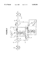
- FIG. 4 is a block diagram of a bidirectional regenerator
- FIG. 5 shows three examples of selection of the wavelength for multi-channel optical transmission systems
- FIG. 6 is a multiple span optical transmission system configuration using common pre/post WDM amplification modules
- FIG. 7A is a paired optical transmission system showing the economy in the fiber spans for working and protection links of a 1:1 linear configuration
- FIG. 7B illustrates paired two-stacked, two fiber rings using WDM amplifier modules
- FIG. 7C is a paired four-fiber ring configuration using WDM amplifier modules.
- WDM couplers or splitters are filters used to separate or combine optical signals according to their wavelength.
- a WDM coupler is used to couple the light from the laser source into the gain region of an EDFA.
- These couplers are very useful in multi-channel optical systems, however, the isolation requirements in the WDM could be a severe issue due to the multi-path interference from imperfect isolation of the splitters.
- Three-port conventional WDM couplers may be used in a configuration as illustrated in the example of FIG. 1A.
- FIG. 1A shows a bidirectional connection between sites A and B where channels of wavelengths ⁇ 1 and ⁇ 2 use the same fiber 1.
- WDM splitter 2 at site A connects transmitter Tx1 to fiber 1 through ports 4 and 3, for launching optical signal S1 of wavelength ⁇ 1 on fiber 1.
- WDM splitter 2 also connects fiber 1 to receiver Rx2 through ports 3 and 5, for directing optical signal S2 of wavelength ⁇ 2 from fiber 1 to receiver Rx2.
- WDM splitter 6 is connected with port 7 to fiber 1 and with port 8 to transmitter Tx2 for launching optical signal S2 on fiber 1, while port 9 is connected to receiver Rx1 for directing the optical signal S1 from fiber 1 to receiver Rx1.
- the four-port filter disclosed in the previously identified U.S. Pat. No. 5,452,124 may be used for obtaining bidirectional amplification using a unidirectional amplifier.
- a bidirectional system configuration using such a four-port WDM splitter is illustrated in FIG. 1B.
- Sites A and B have a similar configuration with that of FIG. 1A.
- Optical signal S1 of wavelength ⁇ 1 travels from site A to site B, while optical signal S2 of wavelength ⁇ 2 travels in an opposite direction of propagation, namely from site B to site A.
- the four-port WDM splitter 10 is provided at a site C, together with a unidirectional optical amplifier 15.
- Splitter 10 routes the traffic so that both channels have the same direction in the gain portion of the amplifier 15.
- signals S1 and S2 received at ports 11 and 12, respectively, are routed in the same direction to exit at port 13, which is connected to the input port of optical amplifier 15.
- the amplified signals S1 and S2 arrive at port 14 of the WDM filter 10 in the same direction of transmission and are launched on fiber 1 in the appropriate direction, according to the wavelength ⁇ 1 or ⁇ 2 .
- the number of channels and the wavelength of each channel are important design parameters for optical transmission systems. It has been noted that the gain of an optical amplifier changes when the power at the input is different (lower or higher) than the nominal power for which the amplifier was designed. This change in the gain with the input power, defined as "gain tilt", is also dependent on the channel wavelength. As an example, FIG. 2A shows the gain of transmission channels 1 and 2 when the amplifier module operates at the nominal gain. FIG. 2B shows the changes in the gain of channels ⁇ 1 and ⁇ 2 when the actual value of the gain is lower than the nominal value. Operating at a higher gain would produce a profile with the opposite slope.
- FIG. 2C shows the change in gain at each wavelength if the gain at 1545 nm is increased by 1 dB.
- WDM is not generally used in the 1530-1542 nm range because of the gain peak with silica-based EDFAs which causes per-channel output power to vary greatly in this region and seriously affects signal gain outside this region when several amplifiers are cascaded.
- the current solutions to address this problem include selectively varying the input power for each channel, or staying in the region of flat gain.
- the first solution causes a significant reduction of the output power of the individual channels, and makes the span engineering difficult.
- the second solution limits the number of channels that can be multiplexed, and also prevents the reuse of the large embedded base of OC-48 transmitters, without the addition of expensive wavelength adapters.
- the optical amplifier gain region of about 1528 nm to 1560 nm is split into two bands: "Blue” for 1528 to 1543 nm, and "Red” for 1547 to 1560 nm.
- the two bands are spatially separated for amplification.
- the wavelength within a band is chosen to be in the regions of similar gain tilt, or to have minimum variation of the gain tilt/dB in the respective "Red” or “Blue” band. This is especially important for the "Blue” gain region, which has large variations in gain tilt, as shown in FIG. 2C.
- FIG. 3 illustrates a block diagram of a bidirectional fiber amplifier, as an example an erbium doped fiber amplifier (EDFA) 15 using spatial separation according to this invention.
- EDFA erbium doped fiber amplifier
- the terms "active optical fiber” and “gain region” designate a length of optical fiber doped with a rare earth element and pumped with coupled waves for amplifying optical signals.
- the optical signals traveling within the central section of optical amplifier 15 are grouped in two bands, each for a direction of transmission in this example.
- the traffic in the Red and Blue bands is physically separated on fibers 17 and 19 using a first three-port WDM splitter 21.
- Signals on fibers 17 and 19 are then recombined by a second three-port WDM splitter 23.
- the amplifier has two peripheral gain spans 25 and 29, and two central gain lengths 27 and 31.
- the signals travel in both directions at the periphery of the amplifier in the gain spans 25 and 29 and in one direction in the central lengths 27 and 31.
- Isolators 33,35, and 37 are also provided and oriented so as to obtain bidirectional operation between the bands.
- This architecture significantly reduces the effect of gain tilt between the two bands and multi-path interference from imperfect isolation of the two splitters.
- the isolation requirements in the WDM splitters 21 and 23 are achievable.
- the noise figure and output power penalty due to the losses of the WDM couplers are reduced.
- the optical fiber exhibits different dispersion characteristics depending on the wavelength used for transmission.
- the two main transmission windows of interest are at 1310 nm for non-dispersion shifted optical fiber, and 1550 nm for dispersion shifted optical fiber.
- the transmitter should preferably be equipped with dispersion compensating modules (DCM) for reducing the significant transmission impairment at high bit rates.
- DCM dispersion compensating modules
- FIG. 4 is a block diagram of a bidirectional regenerator built in accordance with the spatial separation method of the invention. Inserting a four-port WDM router 41 into a fiber carrying bidirectional WDM signals separates the incoming signals according to their direction of propagation. The signals in the "Blue" band arrive, for example, at port 11 on fiber 1', and the signals in the "Red” band arrive at port 12 on fiber 1. These signals exit at port 13 and are routed by WDM router 41 in the same direction from port 13 to the input of a preamplifier 42, then to a dispersion compensating module 43. A three-port WDM splitter 44 separates the signals according to their wavelength and routes them to receivers Rx1 and Rx2 of block 40.
- the signals are passed to two transmitters Tx1 and Tx2. From the two transmitters, the signals are combined with a three-port WDM splitter 45, passed through another dispersion compensation module 46 if needed, and then amplified by a post-amplifier 47.
- the four-port WDM router 41 receives the amplified signals at port 14 and inserts these signals into the two fibers in the appropriate directions.
- FIG. 4 also illustrates how the configuration compensates for the loss introduced by the WDM couplers and DCMs presently available.
- FIG. 5 shows three examples of selection of the wavelength within a band, for obtaining up to eight wavelengths evenly split between the two directions.
- the difference in gain tilt for the two "Blue” channels is relatively large, and it is shown in FIG. 2C at 0.65, while the difference in gain tilt for the two "Red” channels is 0.1. A gain tilt of 0.65 will cause problems in the system.
- the second example shows another selection with two channels in the "Blue” band and two channels in the "Red” band.
- the third example shows a system with eight channels, with four channels in the "Blue” band and four channels in the "Red” band.
- This method of selection of the wavelength of a transmission channel allows multiple wavelengths to be amplified in the Blue band of an erbium doped fiber amplifier without severe gain tilt impairments.
- active equalization between wavelengths may also be obtained by adjusting the transmitted power and also by providing in-line equalization devices when they become available.
- a receiver typically requires -5 dBm of optical power and overloads at 0 dBm, and a transmitter is typically required to launch into the outside plant fiber +7 or +10 dBm.
- These design parameters make it difficult or impossible to design an optical amplifier which simultaneously operates as a pre- and post-amplifier. In addition, these requirements are aggravated by the presence of gain tilt.
- the current transmitters are provided with an optical amplifier configured as a post-amplifier and the receivers are provided with an optical amplifier configured as a pre-amplifier.
- a single fiber amplifier may operate simultaneously as a pre- and post-amplifier according to this invention, by providing separate power control per direction and selecting the wavelength of the channels for minimizing the gain tilt.
- FIG. 6 shows a configuration with bidirectional amplifiers operating as line amplifiers and as combined pre- and post-amplifiers.
- this configuration there are four signals, ⁇ 1 , ⁇ 2 , ⁇ 3 and ⁇ 4 , in the "Red" band, and one signal, ⁇ 5 , in the "Blue” band.
- the DCM 43 and the WDM splitter 2 at site A are separated from the optical cable 62 by the gain of the pre/post-amplifier 60.
- the DCM 45 and the WDM splitter 6 at site B are separated from the optical cable span 63 by the gain of the pre/post-amplifier 61. This reduces the impact of the optical loss of these components on noise and on power level.
- Optical amplifiers 60 and 61 are provided with separate power control per direction, so that amplifier 60 operates as post-amplifier for transmitters Tx1-Tx4 and as pre-amplifier for receiver Rx. Similarly, amplifier 61 operates as a pre-amplifier for receivers Rx1 to Rx4 and as a post-amplifier for transmitter Tx.
- Appropriate selection of wavelength combined with the spatial separation of the channels according to this invention allows for further simplification of the configuration of a multi-channel system.
- a cost effective network may be obtained by reducing the number of protection links.
- FIGS. 7A, 7B and 7C illustrate systems with an equal number of signals in both bands, here called bidirectional pairing.
- bidirectional pairing For each transmitter-receiver path in one direction, there is a receiver-transmitter path in the opposite direction.
- This configuration has significant advantages and reduces the number of protection links.
- a WDM amplifier module as shown in FIG. 3 can be designed to support an equal number of wavelengths in both directions. It is recommended that working and protection groups be provisioned through separate amplifiers in order to prevent exposure to a single amplifier failure.
- FIG. 7A is a balanced bidirectional optical transmission system showing the economy in the fiber spans for working and protection links of a linear configuration of a single 1:1 system.
- One set of amplifiers 52 and 53 is equipped to accommodate the working traffic on fiber 1.
- the protection traffic takes place on a separate route 20 using amplifiers 54, 55, 56, and 57. No more amplifiers are necessary to support a second 1:1 system since the amplifiers support two "Red" band and two "Blue” band wavelengths.
- Further systems may be provisioned to use the same fiber and amplifiers, provided that appropriate wavelengths are available and the link budget can be met.
- a paired bidirectional system requires fewer channels to carry and protect a given amount of data. Fewer channels means fewer fibers, fewer amplifiers, and fewer terminal electronics required to carry the same data.
- FIG. 7B is a configuration of two-stacked, two-fiber rings using WDM amplifier modules as shown in FIG. 3. Because of the bidirectional nature of the amplifiers, only one fiber per span is required to implement a base system. No more amplifiers are thereafter required to implement a second system. Further ring systems can be provisioned to use the same fiber and amplifiers, if appropriate spatial separation and paired wavelength selection are used, as discussed in connection with FIGS. 2C and 5, and the link budget can be met.
- FIG. 7C is a four-fiber ring configuration using the WDM amplifier modules.
- a four-fiber ring may be converted to a "two-fiber ring with span switching". This differs from a normal two-fiber ring in that the four-fiber ring protocol is implemented, allowing such features as span switching.
Abstract
Description
Claims (7)
Priority Applications (1)
| Application Number | Priority Date | Filing Date | Title |
|---|---|---|---|
| US09/110,335 US6101016A (en) | 1996-06-25 | 1998-07-06 | Optical transmission systems using optical amplifiers and wavelength division multiplexing |
Applications Claiming Priority (2)
| Application Number | Priority Date | Filing Date | Title |
|---|---|---|---|
| US08/669,929 US5801858A (en) | 1996-06-25 | 1996-06-25 | Optical transmission systems using optical amplifiers and wavelength division multiplexing |
| US09/110,335 US6101016A (en) | 1996-06-25 | 1998-07-06 | Optical transmission systems using optical amplifiers and wavelength division multiplexing |
Related Parent Applications (1)
| Application Number | Title | Priority Date | Filing Date |
|---|---|---|---|
| US08/669,929 Division US5801858A (en) | 1996-06-25 | 1996-06-25 | Optical transmission systems using optical amplifiers and wavelength division multiplexing |
Publications (1)
| Publication Number | Publication Date |
|---|---|
| US6101016A true US6101016A (en) | 2000-08-08 |
Family
ID=24688312
Family Applications (3)
| Application Number | Title | Priority Date | Filing Date |
|---|---|---|---|
| US08/669,929 Expired - Lifetime US5801858A (en) | 1996-06-25 | 1996-06-25 | Optical transmission systems using optical amplifiers and wavelength division multiplexing |
| US09/110,182 Expired - Lifetime US6067179A (en) | 1996-06-25 | 1998-07-06 | Optical transmission systems using optical amplifiers and wavelength division multiplexing |
| US09/110,335 Expired - Lifetime US6101016A (en) | 1996-06-25 | 1998-07-06 | Optical transmission systems using optical amplifiers and wavelength division multiplexing |
Family Applications Before (2)
| Application Number | Title | Priority Date | Filing Date |
|---|---|---|---|
| US08/669,929 Expired - Lifetime US5801858A (en) | 1996-06-25 | 1996-06-25 | Optical transmission systems using optical amplifiers and wavelength division multiplexing |
| US09/110,182 Expired - Lifetime US6067179A (en) | 1996-06-25 | 1998-07-06 | Optical transmission systems using optical amplifiers and wavelength division multiplexing |
Country Status (9)
| Country | Link |
|---|---|
| US (3) | US5801858A (en) |
| EP (2) | EP1296470B1 (en) |
| JP (1) | JP3544210B2 (en) |
| CN (2) | CN100431289C (en) |
| AU (1) | AU710472B2 (en) |
| CA (1) | CA2257495C (en) |
| DE (2) | DE69630812T2 (en) |
| HK (1) | HK1054135A1 (en) |
| WO (1) | WO1997050203A1 (en) |
Cited By (17)
| Publication number | Priority date | Publication date | Assignee | Title |
|---|---|---|---|---|
| US6243177B1 (en) | 2000-10-03 | 2001-06-05 | Seneca Networks, Inc. | Bidirectional WDM optical communication system with bidirectional add-drop multiplexing |
| US6333798B1 (en) | 2001-02-13 | 2001-12-25 | Seneca Networks, Inc. | Bidirectional WDM optical communication network |
| US20020064131A1 (en) * | 2000-11-07 | 2002-05-30 | Marcus Boesinger | Method for operating a data network |
| US20020163685A1 (en) * | 2001-05-01 | 2002-11-07 | Swanson Eric Arthur | System and method for routing working and protect paths |
| US6480312B1 (en) * | 1997-12-16 | 2002-11-12 | Sumitomo Electric Industries, Ltd. | Dispersion compensating system used for bi-directional optical communication |
| US20020196490A1 (en) * | 2001-06-25 | 2002-12-26 | Corvis Corporation | Optical transmission systems, devices, and methods |
| EP1298956A1 (en) * | 2001-10-01 | 2003-04-02 | Alcatel | Reconfigurable directional optical system |
| US20030133183A1 (en) * | 2001-08-15 | 2003-07-17 | Photon-X, Inc. | Ultra-wide bandwidth optical amplifier |
| US6608709B2 (en) | 2000-10-03 | 2003-08-19 | Gary Duerksen | Bidirectional WDM optical communication system with bidirectional add-drop multiplexing |
| US20040136056A1 (en) * | 2002-08-20 | 2004-07-15 | Nagel Jonathan A. | Method and apparatus for sharing pump energy from a single pump arrangement to optical fibers located in different fiber pairs |
| US20040228632A1 (en) * | 2003-05-14 | 2004-11-18 | Nec Corporation | Single fibre bidirectional optical transmission system and single fibre bidirectional optical amplifier |
| US6839164B2 (en) * | 2000-03-29 | 2005-01-04 | Hitachi, Ltd. | Optical transmission equipment and supervisory system thereof |
| GB2416258A (en) * | 2004-07-13 | 2006-01-18 | Agilent Technologies Inc | Dual optical fibre split data transmission system |
| US20070147845A1 (en) * | 2005-12-28 | 2007-06-28 | Marc Epitaux | Bi-directional parallel optical link |
| WO2007101779A1 (en) * | 2006-03-06 | 2007-09-13 | Nokia Siemens Networks Gmbh & Co. Kg | Bidirectional optical amplifier array |
| US20090067844A1 (en) * | 2006-01-19 | 2009-03-12 | Jean-Luc Archambault | Telecommunications transport methods and systems for extended reach low differential latency |
| EP3355490A1 (en) * | 2017-01-31 | 2018-08-01 | Nokia Solutions and Networks Oy | Optical signal transmission through optical fibres using both co and counter propagating modes |
Families Citing this family (59)
| Publication number | Priority date | Publication date | Assignee | Title |
|---|---|---|---|---|
| JPH08248455A (en) * | 1995-03-09 | 1996-09-27 | Fujitsu Ltd | Optical amplifier for wavelength multiplexing |
| US6369938B1 (en) | 1996-05-28 | 2002-04-09 | Fujitsu Limited | Multi-wavelength light amplifier |
| US5801858A (en) * | 1996-06-25 | 1998-09-01 | Northern Telecom Limited | Optical transmission systems using optical amplifiers and wavelength division multiplexing |
| US6483803B1 (en) * | 1996-09-04 | 2002-11-19 | Nortel Networks Limited | Apparatus and method for restoring fiber optic communications network connections |
| JPH10173264A (en) * | 1996-12-09 | 1998-06-26 | Kokusai Denshin Denwa Co Ltd <Kdd> | Gain equalizer |
| JP3080219B2 (en) * | 1997-01-17 | 2000-08-21 | 日本電気株式会社 | Wavelength multiplexing method, wavelength multiplexing transmission system, and optical path cross connect system |
| US6049417A (en) * | 1997-06-02 | 2000-04-11 | Lucent Technologies Inc. | Wide band optical amplifier |
| GB2327546A (en) * | 1997-07-18 | 1999-01-27 | Northern Telecom Ltd | Optical frequency channel assignment plan and filtering technique to support it |
| EP1000477A1 (en) | 1997-08-01 | 2000-05-17 | Optical Technologies U.S.A. Corp. | Multi-band amplification system for dense wavelength division multiplexing |
| US6631018B1 (en) | 1997-08-27 | 2003-10-07 | Nortel Networks Limited | WDM optical network with passive pass-through at each node |
| US7054559B1 (en) * | 1997-09-04 | 2006-05-30 | Mci Communications Corporation | Method and system for modular multiplexing and amplification in a multi-channel plan |
| KR19990034429A (en) * | 1997-10-29 | 1999-05-15 | 유기범 | Bidirectional Fiber Optic Amplifier Using Isolators |
| US6243179B1 (en) * | 1997-10-31 | 2001-06-05 | Agere Systems Optoelectronics Guardian Corp. | Banded add drop device |
| CA2300941A1 (en) * | 1998-02-20 | 1999-08-26 | Brian L. Lawrence | Multiple-window dense wavelength division multiplexed communications link with optical amplification and dispersion compensation |
| US6602002B1 (en) * | 1998-02-20 | 2003-08-05 | Lucent Technologies Inc. | High capacity optical transmission arrangement |
| US6104527A (en) * | 1998-02-20 | 2000-08-15 | Afc Technologies Inc. | High efficiency bandwidth doubled and gain flattened silica fiber amplifier |
| US6496300B2 (en) | 1998-02-27 | 2002-12-17 | Fujitsu Limited | Optical amplifier |
| US6441955B1 (en) | 1998-02-27 | 2002-08-27 | Fujitsu Limited | Light wavelength-multiplexing systems |
| US6603596B2 (en) * | 1998-03-19 | 2003-08-05 | Fujitsu Limited | Gain and signal level adjustments of cascaded optical amplifiers |
| AU5201999A (en) | 1998-03-25 | 1999-11-01 | Corning Incorporated | Optical-transmission system having a split-gain amplifier and a signal-modifyingdevice |
| US6169616B1 (en) * | 1998-06-04 | 2001-01-02 | Avanex Corporation | Optical and programmable fiber optic wavelength add/drop system |
| US6166850A (en) * | 1998-11-04 | 2000-12-26 | Nortel Networks Limited | Optical amplifier gain control |
| US6211978B1 (en) | 1999-02-10 | 2001-04-03 | Anacom Systems, Inc. | Multi-channel wave division multiplexer system |
| FR2790160B1 (en) * | 1999-02-19 | 2001-05-04 | Cit Alcatel | WDM REGENERATED TRANSMISSION SYSTEM |
| US6661973B1 (en) * | 1999-06-04 | 2003-12-09 | David R. Huber | Optical transmission systems, apparatuses, and methods |
| US6587241B1 (en) * | 1999-08-20 | 2003-07-01 | Corvis Corporation | Optical protection methods, systems, and apparatuses |
| US6885824B1 (en) | 2000-03-03 | 2005-04-26 | Optical Coating Laboratory, Inc. | Expandable optical array |
| DE19945143A1 (en) * | 1999-09-21 | 2001-04-12 | Siemens Ag | Optical transmission system |
| JP2001102666A (en) * | 1999-09-28 | 2001-04-13 | Fujitsu Ltd | Optical amplifier |
| US6307668B1 (en) | 1999-10-04 | 2001-10-23 | Optigain, Inc. | Ultra-wide bandwidth fiber based optical amplifier |
| US6353497B1 (en) | 2000-03-03 | 2002-03-05 | Optical Coating Laboratory, Inc. | Integrated modular optical amplifier |
| TW463474B (en) * | 2000-04-29 | 2001-11-11 | Browave Corp | Structure of bi-direction wavelength optical module |
| KR100506308B1 (en) * | 2000-05-03 | 2005-08-05 | 삼성전자주식회사 | Bidirectional path switching wdm ring network |
| US6459528B1 (en) | 2000-05-23 | 2002-10-01 | Avanex Corporation | Optical passive components and bi-directional amplifier |
| KR100342426B1 (en) * | 2000-10-04 | 2002-07-03 | 윤덕용 | Automatic retrieval of wavelength-division multiplexed ring network |
| US6433924B1 (en) | 2000-11-14 | 2002-08-13 | Optical Coating Laboratory, Inc. | Wavelength-selective optical amplifier |
| US6560257B1 (en) | 2000-11-28 | 2003-05-06 | Harris Corporation | Low power laser driver |
| US6980747B1 (en) | 2000-11-28 | 2005-12-27 | Harris Corporation | Optically amplified receiver |
| US6542277B2 (en) | 2000-12-11 | 2003-04-01 | Harris Corporation | Optically amplified back-up receiver |
| KR100411734B1 (en) * | 2001-02-12 | 2003-12-18 | 한국과학기술원 | Bidirectional wavelength division multiplexed add/drop self-healing Metro-ring network |
| US6748179B2 (en) | 2001-03-07 | 2004-06-08 | Harris Corporation | WDM channel monitoring system and method |
| US6388805B1 (en) | 2001-03-28 | 2002-05-14 | Sycamore Networks, Inc. | Two fiber support with single optical amplifier |
| KR100378111B1 (en) * | 2001-04-02 | 2003-03-29 | 삼성전자주식회사 | Optical amplifier and bidirectional wavelength division multiplexing optical communication system using that |
| US7167648B2 (en) * | 2001-10-24 | 2007-01-23 | Innovative Fiber Optic Solutions, Llc | System and method for an ethernet optical area network |
| JP3831227B2 (en) * | 2001-10-30 | 2006-10-11 | 三菱電機株式会社 | Single core bidirectional transmission equipment |
| US6995900B2 (en) * | 2003-01-21 | 2006-02-07 | Jds Uniphase Corporation | Method of making a short-pass fiber with controlled cut-off wavelength |
| US6909538B2 (en) * | 2002-03-08 | 2005-06-21 | Lightwave Electronics | Fiber amplifiers with depressed cladding and their uses in Er-doped fiber amplifiers for the S-band |
| US6970631B2 (en) | 2002-06-05 | 2005-11-29 | Lightwave Electronics | Suppression of cladding mode loss in fiber amplifiers with distributed suppression of amplified spontaneous emission (ASE) |
| US7239268B1 (en) * | 2002-09-05 | 2007-07-03 | The United States Of America As Represented By The Secretary Of The Army | Method and apparatus for minimizing the number of power amplifiers required under multiple transmission conditions |
| KR100450925B1 (en) * | 2002-09-18 | 2004-10-02 | 삼성전자주식회사 | Light source device of wavelength division multiplexing optical communication system |
| US6922502B2 (en) * | 2003-03-25 | 2005-07-26 | Lucent Technologies Inc. | Optical filtering method and apparatus |
| US7512343B2 (en) * | 2004-07-27 | 2009-03-31 | Ciena Corporation | Bidirectional communication system |
| US20070003283A1 (en) * | 2005-06-29 | 2007-01-04 | At&T Corp. | Dynamic allocation of bandwidth in a bidirectional optical transmission system |
| EP2005622B1 (en) * | 2006-03-31 | 2010-07-28 | BRITISH TELECOMMUNICATIONS public limited company | Method of introducing an outstation into an optical network and outstation therefor |
| JP4941379B2 (en) * | 2008-03-28 | 2012-05-30 | 住友電気工業株式会社 | Station side device, control method thereof, and computer program thereof |
| JP5994508B2 (en) * | 2012-09-18 | 2016-09-21 | 富士通株式会社 | Transmission device, communication system, and transmission level control method |
| PL428292A1 (en) * | 2018-12-20 | 2020-06-29 | Dawis It Spółka Z Ograniczoną Odpowiedzialnością | Method and transmission system for improved one-way or two-way data transmission in the telecommunications network, polarization attractor configuration, computer program and computer program product |
| US11835767B2 (en) * | 2022-03-04 | 2023-12-05 | Alpine Optoelectronics Inc. | Optical subassembly for bidirectional WDM application |
| CN117691444A (en) * | 2024-02-04 | 2024-03-12 | 中国工程物理研究院激光聚变研究中心 | Multistage multiplexing narrow linewidth fiber laser pre-amplification structure |
Citations (10)
| Publication number | Priority date | Publication date | Assignee | Title |
|---|---|---|---|---|
| EP0445364A2 (en) * | 1990-03-07 | 1991-09-11 | Licentia Patent-Verwaltungs-GmbH | Optical communications system |
| US5280549A (en) * | 1993-02-05 | 1994-01-18 | National Research Council Of Canada | Frequency dependent optical isolator |
| WO1994013076A1 (en) * | 1992-12-01 | 1994-06-09 | Scientific-Atlanta, Inc. | An optical communications system for transmitting information signals having different wavelengths over a same optical fiber |
| US5337175A (en) * | 1991-02-11 | 1994-08-09 | Alcatel N.V. | Optical communications system for the subscriber area with optical amplifiers |
| EP0617527A1 (en) * | 1993-03-23 | 1994-09-28 | Nortel Networks Corporation | Transmission systems incorporating optical amplifiers |
| US5452124A (en) * | 1994-03-04 | 1995-09-19 | Williams Telecommunications Group, Inc. | Unidirectional amplification for bi-directional transmission using wavelength-division multiplexing |
| US5548438A (en) * | 1993-12-23 | 1996-08-20 | At&T Corp. | Bidirectional optical amplifier |
| US5604627A (en) * | 1995-05-18 | 1997-02-18 | Robert Bosch Gmbh | Optical amplifier device |
| US5633741A (en) * | 1995-02-23 | 1997-05-27 | Lucent Technologies Inc. | Multichannel optical fiber communications |
| US5801858A (en) * | 1996-06-25 | 1998-09-01 | Northern Telecom Limited | Optical transmission systems using optical amplifiers and wavelength division multiplexing |
-
1996
- 1996-06-25 US US08/669,929 patent/US5801858A/en not_active Expired - Lifetime
- 1996-12-04 AU AU76890/96A patent/AU710472B2/en not_active Expired
- 1996-12-04 DE DE69630812T patent/DE69630812T2/en not_active Expired - Lifetime
- 1996-12-04 CN CNB031410030A patent/CN100431289C/en not_active Expired - Lifetime
- 1996-12-04 EP EP02080042A patent/EP1296470B1/en not_active Expired - Lifetime
- 1996-12-04 JP JP50198598A patent/JP3544210B2/en not_active Expired - Lifetime
- 1996-12-04 DE DE69636554T patent/DE69636554T2/en not_active Expired - Lifetime
- 1996-12-04 CN CNB961804173A patent/CN1149773C/en not_active Expired - Lifetime
- 1996-12-04 EP EP96939787A patent/EP0908034B1/en not_active Expired - Lifetime
- 1996-12-04 CA CA002257495A patent/CA2257495C/en not_active Expired - Lifetime
- 1996-12-04 WO PCT/CA1996/000810 patent/WO1997050203A1/en active IP Right Grant
-
1998
- 1998-07-06 US US09/110,182 patent/US6067179A/en not_active Expired - Lifetime
- 1998-07-06 US US09/110,335 patent/US6101016A/en not_active Expired - Lifetime
-
2003
- 2003-09-03 HK HK03106274A patent/HK1054135A1/en not_active IP Right Cessation
Patent Citations (10)
| Publication number | Priority date | Publication date | Assignee | Title |
|---|---|---|---|---|
| EP0445364A2 (en) * | 1990-03-07 | 1991-09-11 | Licentia Patent-Verwaltungs-GmbH | Optical communications system |
| US5337175A (en) * | 1991-02-11 | 1994-08-09 | Alcatel N.V. | Optical communications system for the subscriber area with optical amplifiers |
| WO1994013076A1 (en) * | 1992-12-01 | 1994-06-09 | Scientific-Atlanta, Inc. | An optical communications system for transmitting information signals having different wavelengths over a same optical fiber |
| US5280549A (en) * | 1993-02-05 | 1994-01-18 | National Research Council Of Canada | Frequency dependent optical isolator |
| EP0617527A1 (en) * | 1993-03-23 | 1994-09-28 | Nortel Networks Corporation | Transmission systems incorporating optical amplifiers |
| US5548438A (en) * | 1993-12-23 | 1996-08-20 | At&T Corp. | Bidirectional optical amplifier |
| US5452124A (en) * | 1994-03-04 | 1995-09-19 | Williams Telecommunications Group, Inc. | Unidirectional amplification for bi-directional transmission using wavelength-division multiplexing |
| US5633741A (en) * | 1995-02-23 | 1997-05-27 | Lucent Technologies Inc. | Multichannel optical fiber communications |
| US5604627A (en) * | 1995-05-18 | 1997-02-18 | Robert Bosch Gmbh | Optical amplifier device |
| US5801858A (en) * | 1996-06-25 | 1998-09-01 | Northern Telecom Limited | Optical transmission systems using optical amplifiers and wavelength division multiplexing |
Non-Patent Citations (6)
| Title |
|---|
| Elrafaie, A. F., "Multiwavelength Survivable Ring Network Architectures," IEEE International Conference on Communications '93, Geneva, Switzerland, vol. 2 of 3, pp. 1245-1251 (May 23, 1993). |
| Elrafaie, A. F., Multiwavelength Survivable Ring Network Architectures, IEEE International Conference on Communications 93, Geneva, Switzerland, vol. 2 of 3, pp. 1245 1251 (May 23, 1993). * |
| Hill, G. R. et al., "Wavelength Routing for Long Haul Networks," IEEE International Conference on Communications, Boston, MA, vol. 2 of 3, pp. 734-738 (Jun. 11, 1989). |
| Hill, G. R. et al., Wavelength Routing for Long Haul Networks, IEEE International Conference on Communications, Boston, MA, vol. 2 of 3, pp. 734 738 (Jun. 11, 1989). * |
| Wu, Tson Ho, Fiber Network Service Survivability, Artech House, pp. 76 78 (1992). * |
| Wu, Tson-Ho, "Fiber Network Service Survivability," Artech House, pp. 76-78 (1992). |
Cited By (31)
| Publication number | Priority date | Publication date | Assignee | Title |
|---|---|---|---|---|
| US6480312B1 (en) * | 1997-12-16 | 2002-11-12 | Sumitomo Electric Industries, Ltd. | Dispersion compensating system used for bi-directional optical communication |
| US6839164B2 (en) * | 2000-03-29 | 2005-01-04 | Hitachi, Ltd. | Optical transmission equipment and supervisory system thereof |
| US6608709B2 (en) | 2000-10-03 | 2003-08-19 | Gary Duerksen | Bidirectional WDM optical communication system with bidirectional add-drop multiplexing |
| US6243177B1 (en) | 2000-10-03 | 2001-06-05 | Seneca Networks, Inc. | Bidirectional WDM optical communication system with bidirectional add-drop multiplexing |
| US20020064131A1 (en) * | 2000-11-07 | 2002-05-30 | Marcus Boesinger | Method for operating a data network |
| US7020088B2 (en) * | 2000-11-07 | 2006-03-28 | Daimlerchrysler Ag | Method for operating a data network |
| US6333798B1 (en) | 2001-02-13 | 2001-12-25 | Seneca Networks, Inc. | Bidirectional WDM optical communication network |
| US20020163685A1 (en) * | 2001-05-01 | 2002-11-07 | Swanson Eric Arthur | System and method for routing working and protect paths |
| US7769290B2 (en) | 2001-06-25 | 2010-08-03 | Broadwing Corporation | Optical transmission systems, devices, and methods |
| US8064763B2 (en) | 2001-06-25 | 2011-11-22 | Level 3 Communications, Llc | Optical transmission systems, devices, and methods |
| US20020196490A1 (en) * | 2001-06-25 | 2002-12-26 | Corvis Corporation | Optical transmission systems, devices, and methods |
| US20030133183A1 (en) * | 2001-08-15 | 2003-07-17 | Photon-X, Inc. | Ultra-wide bandwidth optical amplifier |
| US6927898B2 (en) | 2001-08-15 | 2005-08-09 | Photon-X, Llc | Ultra-wide bandwidth optical amplifier |
| FR2830333A1 (en) * | 2001-10-01 | 2003-04-04 | Cit Alcatel | RE-CONFIGURABLE DIRECTIONAL OPTICAL SYSTEM |
| US20030063840A1 (en) * | 2001-10-01 | 2003-04-03 | Alcatel | Reconfigurable directional optical system |
| EP1298956A1 (en) * | 2001-10-01 | 2003-04-02 | Alcatel | Reconfigurable directional optical system |
| US7254328B2 (en) | 2001-10-01 | 2007-08-07 | Alcatel | Reconfigurable directional optical system |
| WO2004019458A3 (en) * | 2002-08-20 | 2005-04-07 | Red Sky Systems Inc | Sharing pump energy among different fiber pairs |
| US6930825B2 (en) | 2002-08-20 | 2005-08-16 | Red Sky Systems, Inc. | Method and apparatus for sharing pump energy from a single pump arrangement to optical fibers located in different fiber pairs |
| US20040136056A1 (en) * | 2002-08-20 | 2004-07-15 | Nagel Jonathan A. | Method and apparatus for sharing pump energy from a single pump arrangement to optical fibers located in different fiber pairs |
| US7734180B2 (en) * | 2003-05-14 | 2010-06-08 | Nec Corporation | Single fibre bidirectional optical transmission system and single fibre bidirectional optical amplifier |
| US20040228632A1 (en) * | 2003-05-14 | 2004-11-18 | Nec Corporation | Single fibre bidirectional optical transmission system and single fibre bidirectional optical amplifier |
| GB2416258B (en) * | 2004-07-13 | 2008-10-15 | Agilent Technologies Inc | Optical fibre data transmission |
| GB2416258A (en) * | 2004-07-13 | 2006-01-18 | Agilent Technologies Inc | Dual optical fibre split data transmission system |
| US20070147845A1 (en) * | 2005-12-28 | 2007-06-28 | Marc Epitaux | Bi-directional parallel optical link |
| US20090067844A1 (en) * | 2006-01-19 | 2009-03-12 | Jean-Luc Archambault | Telecommunications transport methods and systems for extended reach low differential latency |
| US8467688B2 (en) * | 2006-01-19 | 2013-06-18 | Ciena Corporation | Telecommunications transport methods and systems for extended reach low differential latency |
| US20090028562A1 (en) * | 2006-03-06 | 2009-01-29 | Nokia Siemens Networks Gmbh & Co. Kg | Bidirectional optical amplifier arrangement |
| WO2007101779A1 (en) * | 2006-03-06 | 2007-09-13 | Nokia Siemens Networks Gmbh & Co. Kg | Bidirectional optical amplifier array |
| US8644707B2 (en) | 2006-03-06 | 2014-02-04 | Nokia Siemens Networks Gmbh & Co. Kg | Bidirectional optical amplifier arrangement |
| EP3355490A1 (en) * | 2017-01-31 | 2018-08-01 | Nokia Solutions and Networks Oy | Optical signal transmission through optical fibres using both co and counter propagating modes |
Also Published As
| Publication number | Publication date |
|---|---|
| HK1054135A1 (en) | 2003-11-14 |
| EP1296470A2 (en) | 2003-03-26 |
| JP3544210B2 (en) | 2004-07-21 |
| DE69636554D1 (en) | 2006-10-26 |
| CN1501618A (en) | 2004-06-02 |
| EP0908034A1 (en) | 1999-04-14 |
| CA2257495A1 (en) | 1997-12-31 |
| EP0908034B1 (en) | 2003-11-19 |
| AU7689096A (en) | 1998-01-14 |
| JPH11514180A (en) | 1999-11-30 |
| US6067179A (en) | 2000-05-23 |
| AU710472B2 (en) | 1999-09-23 |
| CN1228220A (en) | 1999-09-08 |
| CN1149773C (en) | 2004-05-12 |
| US5801858A (en) | 1998-09-01 |
| DE69630812T2 (en) | 2004-04-15 |
| CA2257495C (en) | 2000-10-03 |
| EP1296470A3 (en) | 2005-04-06 |
| DE69630812D1 (en) | 2003-12-24 |
| DE69636554T2 (en) | 2007-09-13 |
| WO1997050203A1 (en) | 1997-12-31 |
| CN100431289C (en) | 2008-11-05 |
| EP1296470B1 (en) | 2006-09-13 |
Similar Documents
| Publication | Publication Date | Title |
|---|---|---|
| US6101016A (en) | Optical transmission systems using optical amplifiers and wavelength division multiplexing | |
| US6433903B1 (en) | Optical management channel for wavelength division multiplexed systems | |
| US6137603A (en) | Optical network, optical division and insertion node and recovery system from network failure | |
| JP4371577B2 (en) | Method and apparatus for simultaneous transmission of digital telephone and analog video using wavelength division multiplexing | |
| US6236499B1 (en) | Highly scalable modular optical amplifier based subsystem | |
| US6922529B2 (en) | Optical communications systems, devices, and methods | |
| US20020067539A1 (en) | Optical systems and methods and optical amplifiers for use therein | |
| US6661973B1 (en) | Optical transmission systems, apparatuses, and methods | |
| US6771854B2 (en) | Optical transmission system and optical coupler/branching filter | |
| CA2282607A1 (en) | Method for providing a bidirectional optical supervisory channel | |
| US6757098B2 (en) | Highly scalable modular optical amplifier based subsystem | |
| US7630127B2 (en) | Bidirectional optical amplifier | |
| JP2005536892A (en) | Method and apparatus for distributing pump energy from a single pump device to optical fibers located in different pairs of fibers | |
| US11582539B2 (en) | Method and apparatus for management of a spectral capacity of a wavelength division multiplexing system | |
| JP3149916B2 (en) | WDM optical repeater | |
| EP1249956A2 (en) | In-line hub amplifier structure | |
| US20050111849A1 (en) | Polarization alternating transmission systems, apparatuses, and methods | |
| EP1341334A1 (en) | Polarization alternating transmission systems, apparatuses, and methods | |
| AU2002100257A4 (en) | In-line hub amplifier structure |
Legal Events
| Date | Code | Title | Description |
|---|---|---|---|
| AS | Assignment |
Owner name: NORTEL NETWORKS CORPORATION, CANADA Free format text: CHANGE OF NAME;ASSIGNOR:NORTHERN TELECOM LIMITED;REEL/FRAME:010567/0001 Effective date: 19990429 |
|
| AS | Assignment |
Owner name: NORTEL NETWORKS CORPORATION, CANADA Free format text: CHANGE OF NAME;ASSIGNOR:NORTHERN TELECOM LIMITED;REEL/FRAME:010750/0181 Effective date: 19990429 |
|
| STCF | Information on status: patent grant |
Free format text: PATENTED CASE |
|
| AS | Assignment |
Owner name: NORTEL NETWORKS LIMITED, CANADA Free format text: CHANGE OF NAME;ASSIGNOR:NORTEL NETWORKS CORPORATION;REEL/FRAME:011195/0706 Effective date: 20000830 Owner name: NORTEL NETWORKS LIMITED,CANADA Free format text: CHANGE OF NAME;ASSIGNOR:NORTEL NETWORKS CORPORATION;REEL/FRAME:011195/0706 Effective date: 20000830 |
|
| FEPP | Fee payment procedure |
Free format text: PAYOR NUMBER ASSIGNED (ORIGINAL EVENT CODE: ASPN); ENTITY STATUS OF PATENT OWNER: LARGE ENTITY |
|
| AS | Assignment |
Owner name: JPMORGAN CHASE BANK, TEXAS Free format text: SECURITY AGREEMENT;ASSIGNOR:NORTEL NETWORKS LIMITED;REEL/FRAME:012745/0929 Effective date: 20020404 |
|
| AS | Assignment |
Owner name: NORTEL NETWORKS LIMITED, CANADA Free format text: CHANGE OF NAME;ASSIGNOR:NORTEL NETWORKS CORPORATION;REEL/FRAME:012762/0799 Effective date: 20020404 |
|
| FPAY | Fee payment |
Year of fee payment: 4 |
|
| FPAY | Fee payment |
Year of fee payment: 8 |
|
| AS | Assignment |
Owner name: NORTEL NETWORKS LIMITED,ONTARIO Free format text: RELEASE OF SECURITY INTERESTS;ASSIGNOR:JPMORGAN CHASE BANK, N.A.;REEL/FRAME:024045/0401 Effective date: 20051024 |
|
| AS | Assignment |
Owner name: CIENA LUXEMBOURG S.A.R.L.,LUXEMBOURG Free format text: ASSIGNMENT OF ASSIGNORS INTEREST;ASSIGNOR:NORTEL NETWORKS LIMITED;REEL/FRAME:024213/0653 Effective date: 20100319 Owner name: CIENA LUXEMBOURG S.A.R.L., LUXEMBOURG Free format text: ASSIGNMENT OF ASSIGNORS INTEREST;ASSIGNOR:NORTEL NETWORKS LIMITED;REEL/FRAME:024213/0653 Effective date: 20100319 |
|
| AS | Assignment |
Owner name: CIENA CORPORATION,MARYLAND Free format text: ASSIGNMENT OF ASSIGNORS INTEREST;ASSIGNOR:CIENA LUXEMBOURG S.A.R.L.;REEL/FRAME:024252/0060 Effective date: 20100319 Owner name: CIENA CORPORATION, MARYLAND Free format text: ASSIGNMENT OF ASSIGNORS INTEREST;ASSIGNOR:CIENA LUXEMBOURG S.A.R.L.;REEL/FRAME:024252/0060 Effective date: 20100319 |
|
| FPAY | Fee payment |
Year of fee payment: 12 |
|
| AS | Assignment |
Owner name: DEUTSCHE BANK AG NEW YORK BRANCH, NEW YORK Free format text: SECURITY INTEREST;ASSIGNOR:CIENA CORPORATION;REEL/FRAME:033329/0417 Effective date: 20140715 |
|
| AS | Assignment |
Owner name: BANK OF AMERICA, N.A., AS ADMINISTRATIVE AGENT, NO Free format text: PATENT SECURITY AGREEMENT;ASSIGNOR:CIENA CORPORATION;REEL/FRAME:033347/0260 Effective date: 20140715 |
|
| AS | Assignment |
Owner name: CIENA CORPORATION, MARYLAND Free format text: RELEASE BY SECURED PARTY;ASSIGNOR:DEUTSCHE BANK AG NEW YORK BRANCH;REEL/FRAME:050938/0389 Effective date: 20191028 |
|
| AS | Assignment |
Owner name: BANK OF AMERICA, N.A., AS COLLATERAL AGENT, ILLINO Free format text: PATENT SECURITY AGREEMENT;ASSIGNOR:CIENA CORPORATION;REEL/FRAME:050969/0001 Effective date: 20191028 |
|
| AS | Assignment |
Owner name: CIENA CORPORATION, MARYLAND Free format text: RELEASE BY SECURED PARTY;ASSIGNOR:BANK OF AMERICA, N.A.;REEL/FRAME:065630/0232 Effective date: 20231024 |