US6088875A - Grommet - Google Patents
Grommet Download PDFInfo
- Publication number
- US6088875A US6088875A US09/040,928 US4092898A US6088875A US 6088875 A US6088875 A US 6088875A US 4092898 A US4092898 A US 4092898A US 6088875 A US6088875 A US 6088875A
- Authority
- US
- United States
- Prior art keywords
- cylindrical portion
- grommet
- peripheral surface
- inner peripheral
- annular space
- Prior art date
- Legal status (The legal status is an assumption and is not a legal conclusion. Google has not performed a legal analysis and makes no representation as to the accuracy of the status listed.)
- Expired - Fee Related
Links
Images


Classifications
-
- B—PERFORMING OPERATIONS; TRANSPORTING
- B60—VEHICLES IN GENERAL
- B60R—VEHICLES, VEHICLE FITTINGS, OR VEHICLE PARTS, NOT OTHERWISE PROVIDED FOR
- B60R16/00—Electric or fluid circuits specially adapted for vehicles and not otherwise provided for; Arrangement of elements of electric or fluid circuits specially adapted for vehicles and not otherwise provided for
- B60R16/02—Electric or fluid circuits specially adapted for vehicles and not otherwise provided for; Arrangement of elements of electric or fluid circuits specially adapted for vehicles and not otherwise provided for electric constitutive elements
- B60R16/0207—Wire harnesses
- B60R16/0215—Protecting, fastening and routing means therefor
- B60R16/0222—Grommets
-
- H—ELECTRICITY
- H02—GENERATION; CONVERSION OR DISTRIBUTION OF ELECTRIC POWER
- H02G—INSTALLATION OF ELECTRIC CABLES OR LINES, OR OF COMBINED OPTICAL AND ELECTRIC CABLES OR LINES
- H02G3/00—Installations of electric cables or lines or protective tubing therefor in or on buildings, equivalent structures or vehicles
- H02G3/22—Installations of cables or lines through walls, floors or ceilings, e.g. into buildings
Definitions
- the present invention relates to a grommet for a wire harness which performs a still water by filling a seal material therewithin.
- FIG. 1 shows a conventional grommet disclosed in Japanese Utility Model Unexamined Publication No. 63-2327.
- a grommet 30 is constituted by an elastic grommet body 31, a mounting groove 32 and a seal material 33.
- the grommet body 31 has a first cylindrical portion 34 disposed at one side 31a, a second cylindrical portion 35 disposed at the other side 31b and a third cylindrical portion 36 disposed within the first cylindrical portion 31.
- the third cylindrical portion 36 projects to the one side 31a from an inner peripheral surface 34a of the first cylindrical portion 34.
- An inner peripheral surface 35a of the second cylindrical portion 35 and an inner peripheral surface 36a of the third cylindrical portion 36 defines a harness insertion portion 37 in which a wire harness 40 is inserted from the one side 31a to the other side 31b.
- the mounting groove 32 is annually formed on an outer peripheral surface 34b of the first cylindrical portion 34.
- the seal material 33 is filled in the harness insertion portion 37 in a state that the wire harness 40 is inserted.
- the grommet 30 is mounted to a panel by elastically fitting the mounting groove 32 to a mounting hole of a panel in a vehicle body side.
- An object of the present invention is to provide a grommet which can be easily mounted and has an excellent sound prevention performance.
- a grommet comprising:
- an elastic grommet body having a first cylindrical portion at one side, a second cylindrical portion at the other side and a third cylindrical portion within the first cylindrical portion, the first cylindrical portion having a maximum inner diameter larger than a maximum inner diameter of the second cylindrical portion, the third cylindrical portion projecting to the one side from an inner peripheral surface of the first cylindrical portion, an inner peripheral surface of the second cylindrical portion and an inner peripheral surface of the third cylindrical portion defining a harness insertion portion in which a wire harness is inserted from the one side to the other side, and the inner peripheral surface of the first cylindrical portion and an outer peripheral surface of the third cylindrical portion defining an annular space for allowing the first cylindrical portion to elastically deform;
- a cover portion disposed on an end portion in the one side of the grommet body, the cover portion closing the annular space without affecting an elastic deformation of the first cylindrical portion.
- the grommet is mounted to the panel by elastically fitting the groove to the mounting hole of the panel in the vehicle body side.
- a sound is transmitted through the annular space between two spaces separated by the panel. At this time, since an air layer within the annular space is shut in by the cover portion, the sound is transmitted after shut in the air layer once. Accordingly, a sound prevention performance can be significantly improved.
- the grommet can be easily mounted to the panel.
- FIG. 1 is a partial cross sectional view of a conventional grommet
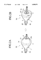
- FIG. 2A is a perspective view of a grommet in accordance with an embodiment of the present invention before a cover portion is inverted;
- FIG. 2B is a perspective view of the grommet shown in FIG. 2A is inverted;
- FIG. 3A is a cross sectional view of FIG. 2A
- FIG. 3B is a cross sectional view of FIG. 2B.
- FIGS. 4A and 4B show cross sectional views of an alternate embodiment of the invention.
- FIGS. 2 and 3 show a grommet in accordance with embodiment of the invention.
- FIG. 2A is a perspective view of a grommet before a cover portion is inverted
- FIG. 2B is a perspective view of the grommet after the cover portion is inverted
- FIG. 3A is a cross sectional view before the cover portion is inverted
- FIG. 3B is a cross sectional view after the cover portion is inverted.
- a grommet 50 is constituted by an elastic grommet body 1, a mounting groove 2, a seal material 3 and a cover portion 19.
- the grommet body 1 has a first cylindrical portion 4 disposed at one side 1a, a second cylindrical portion 5 disposed at the other side 1b and a third cylindrical portion 6 disposed within the first cylindrical portion 4.
- An inner diameter of the first cylindrical portion 4 is expanded toward the one side 1a and is formed larger than a maximum inner diameter of the second cylindrical portion 5.
- An end portion 4c in the one side 1a of the first cylindrical portion 4 has a maximum inner diameter.
- the third cylindrical portion 6 projects from an inner peripheral surface 4a of the first cylindrical portion 4 to the one side 1a.
- An inner peripheral surface 5a of the second cylindrical portion 5 and an inner peripheral surface 6a of the third cylindrical portion 6 define a harness insertion portion 7 in which a wire harness 40 is inserted from the one side 1a to the other side 1b.
- An annular space 8 for allowing the first cylindrical portion 4 to elastically deform is formed between the inner peripheral surface 4a of the first cylindrical portion 4 and an outer peripheral surface 6b of the third cylindrical portion 6.
- the mounting groove 2 is annulary formed on an outer peripheral surface 4b of the end portion 4c of the first cylindrical portion 4.
- the seal material 3 is permeable, waterproof, and filled into a harness insertion portion 7 after the wire harness 40 is inserted.
- the seal material 30 is filled in a gap between the wire harness 50 and the inner peripheral surfaces 5a and 6a and a gap between electric wires constituting the wire harness 50. Accordingly, waterproofing can be securely obtained.
- the grommet 50 can be mounted to the panel 11 by elastically deforming the first cylindrical portion 4 and elastically fitting the mounting groove 2 to a mounting hole 13 of the panel 11 in the vehicle body side (refer to FIG. 3B).
- the first cylindrical portion 4, the second cylindrical portion 5, the third cylindrical portion 6 and the cover portion 19 are integrally formed by an elastic material such as a synthetic resin and the like.
- the cover portion 19 cylindrically extends toward the outer side of the grommet body 1 from the end portion 4c of the first cylindrical portion 4.
- a base end 19a of the cover portion 19 has an inner diameter substantially the same size as an inner diameter of the end portion 4a.
- a front end 19b of the cover portion 19 is tapered and has an inner diameter equal to or slightly smaller than an outer diameter of the third cylindrical portion 6.
- the cover portion 19 is inverted to an inner side and elastically deforms toward the annular space 8, thereby contacting the outer peripheral surface 6a of the third cylindrical portion 6. Accordingly, the cover portion 19 closes the annular space 8 without affecting an elastic deformation of the first cylindrical portion 4.
- a tape 21 is wound around the second cylindrical portion 5 and the wire harness 40.
- the grommet 50 is mounted to the panel 11 by elastically fitting the mounting groove 2 to the mounting hole 13 of the panel 11 in the vehicle body side.
- the panel 11 is, for example, a dash panel disposed between an engine room and a vehicle cabin.
- the sound is transmitted after shut in the air layer. Accordingly, a sound leakage through the grommet 50 between the two spaces can be effectively restricted.
- the panel 11 is the dash panel, it is hard to leak the sound from the engine room to the vehicle cabin, so that a silent state within the vehicle cabin can be maintained.
- the grommet 50 can be simply mounted to the panel 11.
- the cover portion 19 is integrally formed in the first cylindrical portion 4, even when the cover portion 19 is inverted, there is not generated a force of expanding the inner diameter of the third cylindrical portion 6.
- the front end portion 19b of the cover portion 19 elastically presses the outer peripheral surface 6b of the third cylindrical portion 6, a force of reducing the inner diameter of the third cylindrical portion 6 is generated. Accordingly, a close attachment state between the inner peripheral surface 6a of the third cylindrical portion 6 and the hardened seal material 3 can be maintained for a long time, thereby assuring that the waterproofing is also maintained for a long time.
- the cover portion is not limited to a structure which is disposed in the first cylindrical portion 4.
- FIGS. 4A and 4B show a cover portion 19a disposed in the third cylindrical portion 6.
- the cover portion 19a cylindrically extends from one side of the third cylindrical portion 6 and is capable of elastically deforming toward the annular space 8 so that the cover portion 19a contacts the inner peripheral surface 4a of the first cylindrical portion 4.
- the cover portion 19a is integrally formed with the third cylindrical portion 6.
Abstract
A grommet is provided with an elastic grommet body, a mounting groove, a seal material and a cover portion. The grommet body has a first cylindrical portion disposed at one side, a second cylindrical portion disposed at the other end and a third cylindrical portion disposed within the first cylindrical portion. The first cylindrical portion has a maximum inner diameter larger than a maximum inner diameter of the second cylindrical portion. The third cylindrical portion projects to the one side from an inner peripheral surface of the first cylindrical portion. The inner peripheral surface of the second cylindrical portion and the inner peripheral surface of the third cylindrical portion defines a harness insertion portion in which a wire harness is inserted from one side to the other side. The inner peripheral surface of the first cylindrical portion and the outer peripheral surface of the third cylindrical portion defines an annular space for allowing the first cylindrical portion to elastically deform. The mounting groove is annually formed on the outer peripheral surface of the first cylindrical portion. The seal material is filled in the harness insertion portion in a state that the wire harness is inserted. The cover portion is disposed in an end portion of one side of the grommet body and closes the annular space without affecting an elastic deformation of the first cylindrical portion. The grommet can be easily mounted by the closed annular space, and a sound prevention performance can be improved.
Description
The present invention relates to a grommet for a wire harness which performs a still water by filling a seal material therewithin.
FIG. 1 shows a conventional grommet disclosed in Japanese Utility Model Unexamined Publication No. 63-2327.
A grommet 30 is constituted by an elastic grommet body 31, a mounting groove 32 and a seal material 33. The grommet body 31 has a first cylindrical portion 34 disposed at one side 31a, a second cylindrical portion 35 disposed at the other side 31b and a third cylindrical portion 36 disposed within the first cylindrical portion 31.
The third cylindrical portion 36 projects to the one side 31a from an inner peripheral surface 34a of the first cylindrical portion 34. An inner peripheral surface 35a of the second cylindrical portion 35 and an inner peripheral surface 36a of the third cylindrical portion 36 defines a harness insertion portion 37 in which a wire harness 40 is inserted from the one side 31a to the other side 31b.
The mounting groove 32 is annually formed on an outer peripheral surface 34b of the first cylindrical portion 34.
The seal material 33 is filled in the harness insertion portion 37 in a state that the wire harness 40 is inserted.
The grommet 30 is mounted to a panel by elastically fitting the mounting groove 32 to a mounting hole of a panel in a vehicle body side.
However, in the grommet 30 mentioned above, since an annular space 38 for allowing the first cylindrical portion 34 to elastically deform is formed between the inner peripheral surface 34a of the first cylindrical portion 34 and the outer peripheral surface 36b of the third cylindrical portion 36, for example, in the case of mounting the grommet 30 to a dash panel or the like, a sound easily enters into a vehicle cabin from an engine room side through the first cylindrical portion 34 and the annular space 38
On the contrary, a structure for directly filling the seal material into the first cylindrical portion without providing the third cylindrical portion can be considered. However, in this case, an elastic deformation of the first cylindrical portion is restricted by a hardened seal material, so that it is hard to mount the mounting groove to the mounting hole of the panel.
An object of the present invention is to provide a grommet which can be easily mounted and has an excellent sound prevention performance.
In order to achieve the object mentioned above, in accordance with the present invention, there is provided a grommet comprising:
an elastic grommet body having a first cylindrical portion at one side, a second cylindrical portion at the other side and a third cylindrical portion within the first cylindrical portion, the first cylindrical portion having a maximum inner diameter larger than a maximum inner diameter of the second cylindrical portion, the third cylindrical portion projecting to the one side from an inner peripheral surface of the first cylindrical portion, an inner peripheral surface of the second cylindrical portion and an inner peripheral surface of the third cylindrical portion defining a harness insertion portion in which a wire harness is inserted from the one side to the other side, and the inner peripheral surface of the first cylindrical portion and an outer peripheral surface of the third cylindrical portion defining an annular space for allowing the first cylindrical portion to elastically deform;
a mounting groove annually formed on an outer peripheral surface of the first cylindrical portion;
a seal material filled in the harness insertion portion as the wire harness is inserted; and
a cover portion disposed on an end portion in the one side of the grommet body, the cover portion closing the annular space without affecting an elastic deformation of the first cylindrical portion.
In the structure mentioned above, the grommet is mounted to the panel by elastically fitting the groove to the mounting hole of the panel in the vehicle body side.
A sound is transmitted through the annular space between two spaces separated by the panel. At this time, since an air layer within the annular space is shut in by the cover portion, the sound is transmitted after shut in the air layer once. Accordingly, a sound prevention performance can be significantly improved.
Since the first cylindrical portion can be easily deformed in an elastic manner by the annular space, the grommet can be easily mounted to the panel.
After mounted, a still water function can be secured by the seal material filled in the harness insertion portion.
FIG. 1 is a partial cross sectional view of a conventional grommet;
FIG. 2A is a perspective view of a grommet in accordance with an embodiment of the present invention before a cover portion is inverted;
FIG. 2B is a perspective view of the grommet shown in FIG. 2A is inverted;
FIG. 3A is a cross sectional view of FIG. 2A;
FIG. 3B is a cross sectional view of FIG. 2B; and
FIGS. 4A and 4B show cross sectional views of an alternate embodiment of the invention.
An embodiment in accordance with the present invention will be described below with reference to the attached drawings.
FIGS. 2 and 3 show a grommet in accordance with embodiment of the invention. FIG. 2A is a perspective view of a grommet before a cover portion is inverted, FIG. 2B is a perspective view of the grommet after the cover portion is inverted, FIG. 3A is a cross sectional view before the cover portion is inverted and FIG. 3B is a cross sectional view after the cover portion is inverted.
As shown in FIGS. 2A, 2B, 3A and 3B, a grommet 50 is constituted by an elastic grommet body 1, a mounting groove 2, a seal material 3 and a cover portion 19.
The grommet body 1 has a first cylindrical portion 4 disposed at one side 1a, a second cylindrical portion 5 disposed at the other side 1b and a third cylindrical portion 6 disposed within the first cylindrical portion 4. An inner diameter of the first cylindrical portion 4 is expanded toward the one side 1a and is formed larger than a maximum inner diameter of the second cylindrical portion 5. An end portion 4c in the one side 1a of the first cylindrical portion 4 has a maximum inner diameter.
The third cylindrical portion 6 projects from an inner peripheral surface 4a of the first cylindrical portion 4 to the one side 1a. An inner peripheral surface 5a of the second cylindrical portion 5 and an inner peripheral surface 6a of the third cylindrical portion 6 define a harness insertion portion 7 in which a wire harness 40 is inserted from the one side 1a to the other side 1b. An annular space 8 for allowing the first cylindrical portion 4 to elastically deform is formed between the inner peripheral surface 4a of the first cylindrical portion 4 and an outer peripheral surface 6b of the third cylindrical portion 6.
The mounting groove 2 is annulary formed on an outer peripheral surface 4b of the end portion 4c of the first cylindrical portion 4.
The seal material 3 is permeable, waterproof, and filled into a harness insertion portion 7 after the wire harness 40 is inserted. The seal material 30 is filled in a gap between the wire harness 50 and the inner peripheral surfaces 5a and 6a and a gap between electric wires constituting the wire harness 50. Accordingly, waterproofing can be securely obtained.
The grommet 50 can be mounted to the panel 11 by elastically deforming the first cylindrical portion 4 and elastically fitting the mounting groove 2 to a mounting hole 13 of the panel 11 in the vehicle body side (refer to FIG. 3B).
The first cylindrical portion 4, the second cylindrical portion 5, the third cylindrical portion 6 and the cover portion 19 are integrally formed by an elastic material such as a synthetic resin and the like.
As shown in FIG. 2A, the cover portion 19 cylindrically extends toward the outer side of the grommet body 1 from the end portion 4c of the first cylindrical portion 4. A base end 19a of the cover portion 19 has an inner diameter substantially the same size as an inner diameter of the end portion 4a. A front end 19b of the cover portion 19 is tapered and has an inner diameter equal to or slightly smaller than an outer diameter of the third cylindrical portion 6. As shown in FIG. 3B, the cover portion 19 is inverted to an inner side and elastically deforms toward the annular space 8, thereby contacting the outer peripheral surface 6a of the third cylindrical portion 6. Accordingly, the cover portion 19 closes the annular space 8 without affecting an elastic deformation of the first cylindrical portion 4. In this case, a tape 21 is wound around the second cylindrical portion 5 and the wire harness 40.
Next, an operation of this embodiment will be described below.
The grommet 50 is mounted to the panel 11 by elastically fitting the mounting groove 2 to the mounting hole 13 of the panel 11 in the vehicle body side. The panel 11 is, for example, a dash panel disposed between an engine room and a vehicle cabin.
A sound at first enters into the annular space 8 between the two spaces separated by the panel 11. However, since an air layer within the annular space 8 is closed by the cover portion 19, the sound is transmitted after shut in the air layer. Accordingly, a sound leakage through the grommet 50 between the two spaces can be effectively restricted. For example, when the panel 11 is the dash panel, it is hard to leak the sound from the engine room to the vehicle cabin, so that a silent state within the vehicle cabin can be maintained.
Since the first cylindrical portion 4 is easily deformed by the annular space 8, the grommet 50 can be simply mounted to the panel 11.
After mounting the grommet 50, waterproofing can be secured by the seal material 3 filled in the harness insertion portion 7.
Since the cover portion 19 is integrally formed in the first cylindrical portion 4, even when the cover portion 19 is inverted, there is not generated a force of expanding the inner diameter of the third cylindrical portion 6. On the contrary, since the front end portion 19b of the cover portion 19 elastically presses the outer peripheral surface 6b of the third cylindrical portion 6, a force of reducing the inner diameter of the third cylindrical portion 6 is generated. Accordingly, a close attachment state between the inner peripheral surface 6a of the third cylindrical portion 6 and the hardened seal material 3 can be maintained for a long time, thereby assuring that the waterproofing is also maintained for a long time.
In an alternative embodiment, the cover portion is not limited to a structure which is disposed in the first cylindrical portion 4. For example, FIGS. 4A and 4B show a cover portion 19a disposed in the third cylindrical portion 6. The cover portion 19a cylindrically extends from one side of the third cylindrical portion 6 and is capable of elastically deforming toward the annular space 8 so that the cover portion 19a contacts the inner peripheral surface 4a of the first cylindrical portion 4. Preferably, the cover portion 19a is integrally formed with the third cylindrical portion 6.
Claims (8)
1. A grommet comprising:
an elastic grommet body having a first cylindrical portion at one side, a second cylindrical portion at the other side and a third cylindrical portion within the first cylindrical portion, the first cylindrical portion having a maximum inner diameter larger than a maximum inner diameter of the second cylindrical portion, the third cylindrical portion projecting to the one side from an inner peripheral surface of the first cylindrical portion, an inner peripheral surface of the second cylindrical portion and an inner peripheral surface of the third cylindrical portion defining a harness insertion portion in which a wire harness is inserted from the one side to the other side, and the inner peripheral surface of the first cylindrical portion and an outer peripheral surface of the third cylindrical portion defining an annular space for allowing the first cylindrical portion to elastically deform;
a mounting groove annually formed on an outer peripheral surface of the first cylindrical portion;
a seal material filled in the harness insertion portion as the wire harness is inserted; and
a cover portion disposed on an end portion in the one side of the grommet body, the cover portion closing the annular space without affecting an elastic deformation of the first cylindrical portion.
2. A grommet as recited in claim 1, wherein
the cover portion cylindrically extends from the one side of the first cylindrical portion, elastically deforms toward the annular space and is in contact with the outer peripheral surface of the third cylindrical portion.
3. A grommet as recited in claim 2, wherein
the cover portion is integrally formed with the first cylindrical portion.
4. A grommet as recited in claim 2, wherein
the cover portion extends outside the grommet body and is inwardly inverted.
5. A grommet as recited in claim 1, wherein
the cover portion cylindrically extends from the one side of the third cylindrical portion, elastically deforms toward the annular space and is in contact with the inner peripheral surface of the first cylindrical portion.
6. A grommet as recited in claim 5, wherein
the cover portion is integrally formed with the third cylindrical portion.
7. A grommet as recited in claim 5, wherein
the cover portion extends outside the grommet body and is inwardly inverted.
8. A grommet as recited in claim 1, wherein
the seal material has a permeability and a waterproof.
Applications Claiming Priority (2)
| Application Number | Priority Date | Filing Date | Title |
|---|---|---|---|
| JP9068472A JPH10271643A (en) | 1997-03-21 | 1997-03-21 | Cut-off grommet |
| JP9-068472 | 1997-03-21 |
Publications (1)
| Publication Number | Publication Date |
|---|---|
| US6088875A true US6088875A (en) | 2000-07-18 |
Family
ID=13374679
Family Applications (1)
| Application Number | Title | Priority Date | Filing Date |
|---|---|---|---|
| US09/040,928 Expired - Fee Related US6088875A (en) | 1997-03-21 | 1998-03-19 | Grommet |
Country Status (2)
| Country | Link |
|---|---|
| US (1) | US6088875A (en) |
| JP (1) | JPH10271643A (en) |
Cited By (17)
| Publication number | Priority date | Publication date | Assignee | Title |
|---|---|---|---|---|
| US6353185B1 (en) * | 1999-11-18 | 2002-03-05 | Sumitomo Wiring Systems, Ltd. | Grommet and method of installing said grommet on a panel |
| US6372995B1 (en) * | 1999-06-02 | 2002-04-16 | Yazaki Corporation | Grommet |
| EP1207084A1 (en) * | 2000-11-16 | 2002-05-22 | Sumitomo Wiring Systems, Ltd. | Grommet |
| US6486400B1 (en) * | 2001-09-18 | 2002-11-26 | Delphi Technologies, Inc. | Acoustic grommet |
| US6541703B2 (en) * | 2000-03-15 | 2003-04-01 | Sumitomo Wiring Systems, Ltd. | Grommet |
| US6708366B2 (en) * | 2000-01-11 | 2004-03-23 | Yazaki Corporation | Grommet |
| US20040145899A1 (en) * | 2003-01-28 | 2004-07-29 | Riebling Michael L. | In-grade light fixture with hydraulic isolation |
| WO2005006355A1 (en) * | 2003-07-11 | 2005-01-20 | Abb Research Ltd. | Bushing |
| US20080066949A1 (en) * | 2006-09-15 | 2008-03-20 | Preformed Line Products Company | Sealing grommet |
| US7905621B1 (en) | 2008-01-18 | 2011-03-15 | Genlyte Thomas Group, Llc | In-grade lighting fixture |
| US7926970B2 (en) | 2008-01-18 | 2011-04-19 | Genlyte Thomas Group Llc | In-grade lighting fixture |
| US20120218070A1 (en) * | 2011-02-25 | 2012-08-30 | Rockwell Automation Technologies, Inc. | Insulating support flange for current loop system |
| CN103206577A (en) * | 2013-03-12 | 2013-07-17 | 北京新立机械有限责任公司 | Cable bundle flange filling and sealing method |
| US8944718B2 (en) | 2010-09-23 | 2015-02-03 | C-Flex Bearing Co., Inc. | Clamping bushing |
| US10300868B2 (en) * | 2015-10-19 | 2019-05-28 | Sumitomo Wiring Systems, Ltd. | Grommet and wire harness |
| US20200079301A1 (en) * | 2016-12-19 | 2020-03-12 | Sumitomo Wiring Systems, Ltd. | Holding structure for protection member of wire harness |
| US20210262589A1 (en) * | 2020-02-21 | 2021-08-26 | Commscope Technologies Llc | Cable anchor assembly |
Families Citing this family (3)
| Publication number | Priority date | Publication date | Assignee | Title |
|---|---|---|---|---|
| KR100488771B1 (en) * | 2001-12-17 | 2005-05-12 | 현대자동차주식회사 | Elasticity grommet of Automobile |
| JP5986849B2 (en) * | 2012-08-29 | 2016-09-06 | 矢崎総業株式会社 | Grommet and sealed structure |
| JP7159235B2 (en) * | 2020-02-17 | 2022-10-24 | 矢崎総業株式会社 | Grommet and wire harness |
Citations (9)
| Publication number | Priority date | Publication date | Assignee | Title |
|---|---|---|---|---|
| US24438A (en) * | 1859-06-21 | Island | ||
| US2690470A (en) * | 1950-08-02 | 1954-09-28 | Walter H Moorhead | Flexible grommet |
| JPS632327A (en) * | 1986-06-20 | 1988-01-07 | Sanyo Electric Co Ltd | Etching of fine pattern |
| JPH0442982A (en) * | 1990-06-06 | 1992-02-13 | Shinko Electric Ind Co Ltd | Glass sealed terminal for semiconductor laser element |
| US5499823A (en) * | 1994-02-17 | 1996-03-19 | Sumitomo Wiring Systems, Ltd. | Grommet with filler inlet opening |
| US5526549A (en) * | 1993-07-01 | 1996-06-18 | Sumitomo Wiring Systems, Ltd. | Grommet |
| JPH08294214A (en) * | 1995-04-19 | 1996-11-05 | Yazaki Corp | Grommet |
| US5635678A (en) * | 1993-06-08 | 1997-06-03 | Sumitomo Wiring Systems, Ltd. | Construction for and method of waterproofing wiring harness |
| US5774934A (en) * | 1996-03-29 | 1998-07-07 | Sumitomo Wiring Systems, Ltd. | Grommet and a method for mounting a grommet |
-
1997
- 1997-03-21 JP JP9068472A patent/JPH10271643A/en active Pending
-
1998
- 1998-03-19 US US09/040,928 patent/US6088875A/en not_active Expired - Fee Related
Patent Citations (9)
| Publication number | Priority date | Publication date | Assignee | Title |
|---|---|---|---|---|
| US24438A (en) * | 1859-06-21 | Island | ||
| US2690470A (en) * | 1950-08-02 | 1954-09-28 | Walter H Moorhead | Flexible grommet |
| JPS632327A (en) * | 1986-06-20 | 1988-01-07 | Sanyo Electric Co Ltd | Etching of fine pattern |
| JPH0442982A (en) * | 1990-06-06 | 1992-02-13 | Shinko Electric Ind Co Ltd | Glass sealed terminal for semiconductor laser element |
| US5635678A (en) * | 1993-06-08 | 1997-06-03 | Sumitomo Wiring Systems, Ltd. | Construction for and method of waterproofing wiring harness |
| US5526549A (en) * | 1993-07-01 | 1996-06-18 | Sumitomo Wiring Systems, Ltd. | Grommet |
| US5499823A (en) * | 1994-02-17 | 1996-03-19 | Sumitomo Wiring Systems, Ltd. | Grommet with filler inlet opening |
| JPH08294214A (en) * | 1995-04-19 | 1996-11-05 | Yazaki Corp | Grommet |
| US5774934A (en) * | 1996-03-29 | 1998-07-07 | Sumitomo Wiring Systems, Ltd. | Grommet and a method for mounting a grommet |
Cited By (23)
| Publication number | Priority date | Publication date | Assignee | Title |
|---|---|---|---|---|
| US6372995B1 (en) * | 1999-06-02 | 2002-04-16 | Yazaki Corporation | Grommet |
| US6353185B1 (en) * | 1999-11-18 | 2002-03-05 | Sumitomo Wiring Systems, Ltd. | Grommet and method of installing said grommet on a panel |
| US6708366B2 (en) * | 2000-01-11 | 2004-03-23 | Yazaki Corporation | Grommet |
| US6541703B2 (en) * | 2000-03-15 | 2003-04-01 | Sumitomo Wiring Systems, Ltd. | Grommet |
| EP1207084A1 (en) * | 2000-11-16 | 2002-05-22 | Sumitomo Wiring Systems, Ltd. | Grommet |
| US6486400B1 (en) * | 2001-09-18 | 2002-11-26 | Delphi Technologies, Inc. | Acoustic grommet |
| US20040145899A1 (en) * | 2003-01-28 | 2004-07-29 | Riebling Michael L. | In-grade light fixture with hydraulic isolation |
| US7011436B2 (en) | 2003-01-28 | 2006-03-14 | Genlyte Thomas Group, Llc | In-grade light fixture with hydraulic isolation |
| US7964799B2 (en) | 2003-07-11 | 2011-06-21 | Abb Research Ltd. | Bushing |
| WO2005006355A1 (en) * | 2003-07-11 | 2005-01-20 | Abb Research Ltd. | Bushing |
| US20080066949A1 (en) * | 2006-09-15 | 2008-03-20 | Preformed Line Products Company | Sealing grommet |
| US7905621B1 (en) | 2008-01-18 | 2011-03-15 | Genlyte Thomas Group, Llc | In-grade lighting fixture |
| US7926970B2 (en) | 2008-01-18 | 2011-04-19 | Genlyte Thomas Group Llc | In-grade lighting fixture |
| US8944718B2 (en) | 2010-09-23 | 2015-02-03 | C-Flex Bearing Co., Inc. | Clamping bushing |
| US20120218070A1 (en) * | 2011-02-25 | 2012-08-30 | Rockwell Automation Technologies, Inc. | Insulating support flange for current loop system |
| US8952275B2 (en) * | 2011-02-25 | 2015-02-10 | Rockwell Automation Technologies, Inc. | Insulating support flange for current loop system |
| US9576723B2 (en) | 2011-02-25 | 2017-02-21 | Rockwell Automation Technologies, Inc. | Insulating support flange for current loop system |
| CN103206577A (en) * | 2013-03-12 | 2013-07-17 | 北京新立机械有限责任公司 | Cable bundle flange filling and sealing method |
| CN103206577B (en) * | 2013-03-12 | 2017-09-29 | 北京新立机械有限责任公司 | A kind of cable bundle flange perfusion and encapsulating method |
| US10300868B2 (en) * | 2015-10-19 | 2019-05-28 | Sumitomo Wiring Systems, Ltd. | Grommet and wire harness |
| US20200079301A1 (en) * | 2016-12-19 | 2020-03-12 | Sumitomo Wiring Systems, Ltd. | Holding structure for protection member of wire harness |
| US20210262589A1 (en) * | 2020-02-21 | 2021-08-26 | Commscope Technologies Llc | Cable anchor assembly |
| US11841099B2 (en) * | 2020-02-21 | 2023-12-12 | Commscope Technologies Llc | Cable anchor assembly |
Also Published As
| Publication number | Publication date |
|---|---|
| JPH10271643A (en) | 1998-10-09 |
Similar Documents
| Publication | Publication Date | Title |
|---|---|---|
| US6088875A (en) | Grommet | |
| KR101335080B1 (en) | Grommet for wire harness | |
| JPH07307182A (en) | Water-proofing rubber plug and water-proofing connector | |
| US6343953B2 (en) | Structure for assembling a housing and a connector | |
| JP2021132422A (en) | Grommet and wire harness | |
| JP2021061679A (en) | Grommet and wiring harness | |
| JP2914195B2 (en) | Plug cap for internal combustion engine | |
| JP3106958B2 (en) | Grommet | |
| JPH0226139Y2 (en) | ||
| JP2001313113A (en) | Waterproof connector | |
| JP6673429B2 (en) | Grommets and wire harnesses | |
| JP3032952B2 (en) | Seal structure of waterproof box | |
| JP2976837B2 (en) | Grommet | |
| JP2003153416A (en) | Attachment structure of grommet | |
| JPH08308067A (en) | Grommet | |
| JPS6240224Y2 (en) | ||
| JPH09120728A (en) | Grommet | |
| JPH039214Y2 (en) | ||
| JPH0922631A (en) | Fully closed type grommet | |
| JP3396558B2 (en) | Back cover device of speaker grill | |
| JP2514195Y2 (en) | Waterproof connector | |
| JP2002111246A (en) | Water-proof structure of housing | |
| JPH07201403A (en) | Waterproof plug for connector and waterproof plug fitting structure | |
| JP2000249261A (en) | Grommet and fitting method of grommet to panel | |
| JPH0140224Y2 (en) |
Legal Events
| Date | Code | Title | Description |
|---|---|---|---|
| AS | Assignment |
Owner name: YAZAKI CORPORATION, JAPAN Free format text: ASSIGNMENT OF ASSIGNORS INTEREST;ASSIGNORS:ONO, MAMORU;SEKI, YOSHINOBU;REEL/FRAME:009219/0839 Effective date: 19980518 |
|
| REMI | Maintenance fee reminder mailed | ||
| LAPS | Lapse for failure to pay maintenance fees | ||
| FP | Lapsed due to failure to pay maintenance fee |
Effective date: 20040718 |
|
| STCH | Information on status: patent discontinuation |
Free format text: PATENT EXPIRED DUE TO NONPAYMENT OF MAINTENANCE FEES UNDER 37 CFR 1.362 |