US6085401A - Flexible auto riveter skin/stringer assembly cell - Google Patents
Flexible auto riveter skin/stringer assembly cell Download PDFInfo
- Publication number
- US6085401A US6085401A US09/287,479 US28747999A US6085401A US 6085401 A US6085401 A US 6085401A US 28747999 A US28747999 A US 28747999A US 6085401 A US6085401 A US 6085401A
- Authority
- US
- United States
- Prior art keywords
- stringer
- piston
- lower upset
- upset post
- cylinder
- Prior art date
- Legal status (The legal status is an assumption and is not a legal conclusion. Google has not performed a legal analysis and makes no representation as to the accuracy of the status listed.)
- Expired - Fee Related
Links
Images

Classifications
-
- B—PERFORMING OPERATIONS; TRANSPORTING
- B21—MECHANICAL METAL-WORKING WITHOUT ESSENTIALLY REMOVING MATERIAL; PUNCHING METAL
- B21J—FORGING; HAMMERING; PRESSING METAL; RIVETING; FORGE FURNACES
- B21J15/00—Riveting
- B21J15/10—Riveting machines
- B21J15/14—Riveting machines specially adapted for riveting specific articles, e.g. brake lining machines
- B21J15/142—Aerospace structures
-
- B—PERFORMING OPERATIONS; TRANSPORTING
- B21—MECHANICAL METAL-WORKING WITHOUT ESSENTIALLY REMOVING MATERIAL; PUNCHING METAL
- B21J—FORGING; HAMMERING; PRESSING METAL; RIVETING; FORGE FURNACES
- B21J15/00—Riveting
- B21J15/10—Riveting machines
-
- B—PERFORMING OPERATIONS; TRANSPORTING
- B21—MECHANICAL METAL-WORKING WITHOUT ESSENTIALLY REMOVING MATERIAL; PUNCHING METAL
- B21J—FORGING; HAMMERING; PRESSING METAL; RIVETING; FORGE FURNACES
- B21J15/00—Riveting
- B21J15/38—Accessories for use in connection with riveting, e.g. pliers for upsetting; Hand tools for riveting
- B21J15/42—Special clamping devices for workpieces to be riveted together, e.g. operating through the rivet holes
-
- B—PERFORMING OPERATIONS; TRANSPORTING
- B21—MECHANICAL METAL-WORKING WITHOUT ESSENTIALLY REMOVING MATERIAL; PUNCHING METAL
- B21J—FORGING; HAMMERING; PRESSING METAL; RIVETING; FORGE FURNACES
- B21J15/00—Riveting
- B21J15/38—Accessories for use in connection with riveting, e.g. pliers for upsetting; Hand tools for riveting
- B21J15/44—Rivet hole positioners
-
- Y—GENERAL TAGGING OF NEW TECHNOLOGICAL DEVELOPMENTS; GENERAL TAGGING OF CROSS-SECTIONAL TECHNOLOGIES SPANNING OVER SEVERAL SECTIONS OF THE IPC; TECHNICAL SUBJECTS COVERED BY FORMER USPC CROSS-REFERENCE ART COLLECTIONS [XRACs] AND DIGESTS
- Y10—TECHNICAL SUBJECTS COVERED BY FORMER USPC
- Y10T—TECHNICAL SUBJECTS COVERED BY FORMER US CLASSIFICATION
- Y10T29/00—Metal working
- Y10T29/49—Method of mechanical manufacture
- Y10T29/49826—Assembling or joining
- Y10T29/49947—Assembling or joining by applying separate fastener
- Y10T29/49954—Fastener deformed after application
- Y10T29/49956—Riveting
-
- Y—GENERAL TAGGING OF NEW TECHNOLOGICAL DEVELOPMENTS; GENERAL TAGGING OF CROSS-SECTIONAL TECHNOLOGIES SPANNING OVER SEVERAL SECTIONS OF THE IPC; TECHNICAL SUBJECTS COVERED BY FORMER USPC CROSS-REFERENCE ART COLLECTIONS [XRACs] AND DIGESTS
- Y10—TECHNICAL SUBJECTS COVERED BY FORMER USPC
- Y10T—TECHNICAL SUBJECTS COVERED BY FORMER US CLASSIFICATION
- Y10T29/00—Metal working
- Y10T29/49—Method of mechanical manufacture
- Y10T29/49998—Work holding
-
- Y—GENERAL TAGGING OF NEW TECHNOLOGICAL DEVELOPMENTS; GENERAL TAGGING OF CROSS-SECTIONAL TECHNOLOGIES SPANNING OVER SEVERAL SECTIONS OF THE IPC; TECHNICAL SUBJECTS COVERED BY FORMER USPC CROSS-REFERENCE ART COLLECTIONS [XRACs] AND DIGESTS
- Y10—TECHNICAL SUBJECTS COVERED BY FORMER USPC
- Y10T—TECHNICAL SUBJECTS COVERED BY FORMER US CLASSIFICATION
- Y10T29/00—Metal working
- Y10T29/53—Means to assemble or disassemble
- Y10T29/53709—Overedge assembling means
- Y10T29/5377—Riveter
-
- Y—GENERAL TAGGING OF NEW TECHNOLOGICAL DEVELOPMENTS; GENERAL TAGGING OF CROSS-SECTIONAL TECHNOLOGIES SPANNING OVER SEVERAL SECTIONS OF THE IPC; TECHNICAL SUBJECTS COVERED BY FORMER USPC CROSS-REFERENCE ART COLLECTIONS [XRACs] AND DIGESTS
- Y10—TECHNICAL SUBJECTS COVERED BY FORMER USPC
- Y10T—TECHNICAL SUBJECTS COVERED BY FORMER US CLASSIFICATION
- Y10T29/00—Metal working
- Y10T29/53—Means to assemble or disassemble
- Y10T29/53961—Means to assemble or disassemble with work-holder for assembly
- Y10T29/5397—Means to assemble or disassemble with work-holder for assembly and assembling press [e.g., truss assembling means, etc.]
-
- Y—GENERAL TAGGING OF NEW TECHNOLOGICAL DEVELOPMENTS; GENERAL TAGGING OF CROSS-SECTIONAL TECHNOLOGIES SPANNING OVER SEVERAL SECTIONS OF THE IPC; TECHNICAL SUBJECTS COVERED BY FORMER USPC CROSS-REFERENCE ART COLLECTIONS [XRACs] AND DIGESTS
- Y10—TECHNICAL SUBJECTS COVERED BY FORMER USPC
- Y10T—TECHNICAL SUBJECTS COVERED BY FORMER US CLASSIFICATION
- Y10T29/00—Metal working
- Y10T29/53—Means to assemble or disassemble
- Y10T29/53978—Means to assemble or disassemble including means to relatively position plural work parts
Definitions
- This invention relates to the assembly of components, and particularly to the precision location to engineering and riveting of aircraft panels to stringers.
- Aircraft structural components are typically constructed by riveting a skin panel to a series of load bearing stringers with rivets. These rivets are usually installed flush with the outer surface of the skin to reduce drag.
- a jig is provided for positioning a stringer relative to a skin portion to secure the skin and stringer together.
- the jig includes a fixed member defining a hard locator surface and a movable member urging the stringer against the hard locator surface to position the stringer relative the jig.
- the fixed member is the lower ram of a riveting device, such as the lower upset post.
- a first cylinder having a piston is mounted to the fixed member, the movable member is mounted on the piston for movement relative the fixed member.
- the cylinder is mounted on a rotatable mount relative the fixed member.
- FIG. 1 is a perspective view of a riveting mechanism permitting multi-axis motion
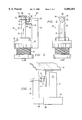
- FIG. 2 is a side view of a mechanism forming a first embodiment of the present invention
- FIG. 3 is an end view of the mechanism
- FIG. 4 is a plan view of the mechanism
- FIG. 5 is a view of a modified mechanism.
- FIG. 1 illustrates a riveting mechanism 10 which is capable of riveting a skin 12, typically of an aircraft, to a series of stiffening stringers 14 (as seen in FIG. 2).
- the mechanism includes a frame 16 which mounts a sliding jig 18 for motion along the frame in an X-axis direction 20.
- the frame 16 is mounted on a series of positioners 22 which allow the frame to be moved in the vertical or Z-axis direction 24.
- a riveter 26 is mounted on a slidable base 28 which allows the riveter 26 to move in the Y-axis direction 30 which is perpendicular to both the X-axis and Z-axis.
- the riveter 26 has a lower upset post 32, as seen in FIG. 2, which extends upwardly from underneath the skin 12.
- a head 34 above the skin mounts drilling and riveting mechanisms of a type well known in the industry.
- a rivet is normally installed between the skin and stringer near one end thereof to initially position the stringer.
- the skin is precisely positioned within the frame 16 and its position relative to the riveter 26 is thus established. However, the position of the stringer 14 is not.
- the mechanism 36 shown in FIGS. 2-4 is capable of precisely positioning the stringer relative the riveter 26 and skin 12 to provide accurate riveting thereto.
- the mechanism 36 includes the conventional lower upset post 32 of the riveter 26.
- the upper end of the post 32 defines a hard locator surface 38, also known as the hard stop $ location.
- the skin 12 is located in precise orientation to the lower upset post 32 by the frame 16 and jig 18. However, the exact position of the stringer 14 is indeterminate.
- the post 32 can move vertically along the Z-axis 24 to move up against the stringer and skin and can rotate about the vertical Z-axis 24.
- the post 32 is rotated to position an eccentric surface 46 on the upper end of the post 32 to a position where the stringer should be located in the plane containing the X and Y axis.
- a collar 40 is mounted on the post 32 through a bearing 42 and is urged upwardly by a spring 44.
- a vertical member 48 extends upwardly from the collar 40 to support a cylinder 50 having a piston 52.
- the cylinder can be operated by hydraulic fluid, air, or any other suitable mechanism. It can also be an electric solenoid actuator.
- Mounted on the piston 52 is a roller 54 which is mounted for free rotation about the vertical Z-axis 24. To position the stringer 14 relative the skin 12, the piston 52 is initially retracted to draw the roller 54 toward the vertical member 48 and away from the surface 46. The riveter 26 is moved directly under the position the stringer is to be secured to the skin and the lower upset post 32 is raised until the hard locator surface 38 is proximate the skin and in position for riveting.
- the stringer will generally be in approximately the correct position relative the skin 12 so that the vertical member and roller 54 will clear the lower arm 56 of the stringer 14.
- the vertical member 48 can be mounted to the collar 40 through a second cylinder 58, with the cylinder 58 mounted on the collar and the vertical member 48 mounted on the piston 60 thereof. This would permit the vertical member 48 and roller 54 to be moved even further away from the lower upset post 32 to orient the post in the desired position in tight quarters between the skin and stringers.
- the lower upset post 32 can be rotated about the Z-axis to move the eccentric surface 46 to the proper position for the stringer 14 in a manner well known in the industry. It should be noted that the surface 46 may not in fact even contact the stringer as it moves to this position. The surface simply defines the position where the inner surface 62 of the intermediate arm 64 of the stringer 14 should be positioned. The cylinder 50 can then be activated to extend the piston 52 until the roller 54 comes into contact with the outer side 66 of the intermediate arm 64. The piston and roller then push the stringer into the desired position against the eccentric surface 46 of the lower upset post 32, as seen in FIG. 2, and hold the stringer in this position by maintaining pressure in cylinder 50.
- the rivet hole 68 can be bored through both the skin 12 and the stringer 14. Because the lower upset post 32 can provide sufficient clamp up pressure on the skin 12 and stringer 14, the hole 68 can be drilled without the need to subsequently separate the skin and stringer from each other to debur the hole.
- the riveter 26 then functions to install the rivet and machine flush the end surface of the rivet with the outer surface of the skin to finish the operation.
- the frame 16, jig 18 and riveter 26 are moved as necessary in the X-axis, Y-axis and Z-axis directions to properly position the lower upset post 32 in the proper position for installing the rivet.
- the piston 52 can be activated the move the roller 54 against the stringer to properly position the stringer 14 relative to the skin 12 and riveting mechanism 10.
Abstract
Description
Claims (18)
Priority Applications (1)
| Application Number | Priority Date | Filing Date | Title |
|---|---|---|---|
| US09/287,479 US6085401A (en) | 1995-09-29 | 1999-04-06 | Flexible auto riveter skin/stringer assembly cell |
Applications Claiming Priority (2)
| Application Number | Priority Date | Filing Date | Title |
|---|---|---|---|
| US08/536,032 US5937502A (en) | 1995-09-29 | 1995-09-29 | Flexible auto-riveter skin/stringer assembly cell |
| US09/287,479 US6085401A (en) | 1995-09-29 | 1999-04-06 | Flexible auto riveter skin/stringer assembly cell |
Related Parent Applications (1)
| Application Number | Title | Priority Date | Filing Date |
|---|---|---|---|
| US08/536,032 Division US5937502A (en) | 1995-09-29 | 1995-09-29 | Flexible auto-riveter skin/stringer assembly cell |
Publications (1)
| Publication Number | Publication Date |
|---|---|
| US6085401A true US6085401A (en) | 2000-07-11 |
Family
ID=24136852
Family Applications (2)
| Application Number | Title | Priority Date | Filing Date |
|---|---|---|---|
| US08/536,032 Expired - Fee Related US5937502A (en) | 1995-09-29 | 1995-09-29 | Flexible auto-riveter skin/stringer assembly cell |
| US09/287,479 Expired - Fee Related US6085401A (en) | 1995-09-29 | 1999-04-06 | Flexible auto riveter skin/stringer assembly cell |
Family Applications Before (1)
| Application Number | Title | Priority Date | Filing Date |
|---|---|---|---|
| US08/536,032 Expired - Fee Related US5937502A (en) | 1995-09-29 | 1995-09-29 | Flexible auto-riveter skin/stringer assembly cell |
Country Status (1)
| Country | Link |
|---|---|
| US (2) | US5937502A (en) |
Cited By (1)
| Publication number | Priority date | Publication date | Assignee | Title |
|---|---|---|---|---|
| US20140195486A1 (en) * | 2013-01-08 | 2014-07-10 | Facebook, Inc. | Data recovery in multi-leader distributed systems |
Families Citing this family (3)
| Publication number | Priority date | Publication date | Assignee | Title |
|---|---|---|---|---|
| US5937502A (en) * | 1995-09-29 | 1999-08-17 | Northrop Grumman Corporation | Flexible auto-riveter skin/stringer assembly cell |
| CN110560623B (en) * | 2019-09-09 | 2020-08-04 | 赣州市恒邦金属制品有限公司 | Automatic processing system for sheet metal parts |
| CN113650196B (en) * | 2021-07-27 | 2023-04-14 | 中航西安飞机工业集团股份有限公司 | Accurate positioning device for T-shaped wet stringer forming die and using method |
Citations (20)
| Publication number | Priority date | Publication date | Assignee | Title |
|---|---|---|---|---|
| US912297A (en) * | 1906-02-27 | 1909-02-16 | Georges Ermel | Riveting-machine. |
| US2365147A (en) * | 1941-01-31 | 1944-12-12 | Wilbur Johndrew | Riveting machine |
| US2920783A (en) * | 1953-08-20 | 1960-01-12 | Fed Pacific Electric Co | Automatic riveting apparatus |
| US3200487A (en) * | 1963-11-12 | 1965-08-17 | Aubrey L Hilscher | Method and means to produce folders with eyelets and tangs |
| US3747193A (en) * | 1970-06-09 | 1973-07-24 | Rohr Corp | Automatic riveting device |
| US4310964A (en) * | 1979-01-02 | 1982-01-19 | The Boeing Company | Method and apparatus for the automated assembly of major subassemblies |
| JPS58192646A (en) * | 1982-04-30 | 1983-11-10 | Brother Ind Ltd | Rivet fitting command preparing device for machine for fitting rivet to sheet-like material |
| SU1123834A1 (en) * | 1982-07-21 | 1984-11-15 | Предприятие П/Я А-1575 | Quick-readjustable appliance |
| US4858289A (en) * | 1983-05-06 | 1989-08-22 | Gemcor Engineering Corp. | Dimpling and riveting apparatus |
| US4930206A (en) * | 1988-05-26 | 1990-06-05 | Fuji Jukogyo Kabushiki Kaisha | Apparatus and method for fixing and positioning a nut plate |
| US5142764A (en) * | 1990-11-28 | 1992-09-01 | The United States Of America As Represented By The Secretary Of The Air Force | Method for tack-free positioning of aircraft components for subsequent fastening |
| US5199147A (en) * | 1990-11-28 | 1993-04-06 | The United States Of America As Represented By The Secretary Of The Air Force | Movable jig assembly for the manufacture of aircraft components |
| US5201205A (en) * | 1991-09-16 | 1993-04-13 | Electroimpact, Inc. | Two axis tracer for fastener operations |
| US5231747A (en) * | 1990-12-21 | 1993-08-03 | The Boeing Company | Drill/rivet device |
| US5329691A (en) * | 1992-11-04 | 1994-07-19 | Gemcor Engineering Corporation | Hole probe apparatus |
| US5341556A (en) * | 1991-06-28 | 1994-08-30 | The United States Of America As Represented By The Secretary Of The Air Force | Method and apparatus for manufacture of reinforced panels |
| US5404641A (en) * | 1993-08-16 | 1995-04-11 | Avco Corporation | Method of drilling through contiguous plate members using a robotic drill clamp |
| US5901426A (en) * | 1995-12-28 | 1999-05-11 | Honda Giken Kogyo Kabushiki Kaisha | Method of combining workpieces |
| US5937502A (en) * | 1995-09-29 | 1999-08-17 | Northrop Grumman Corporation | Flexible auto-riveter skin/stringer assembly cell |
| US5968399A (en) * | 1995-10-17 | 1999-10-19 | Tetra Laval Holdings & Finance, S.A. | Inductor for induction sealing of packing material |
-
1995
- 1995-09-29 US US08/536,032 patent/US5937502A/en not_active Expired - Fee Related
-
1999
- 1999-04-06 US US09/287,479 patent/US6085401A/en not_active Expired - Fee Related
Patent Citations (20)
| Publication number | Priority date | Publication date | Assignee | Title |
|---|---|---|---|---|
| US912297A (en) * | 1906-02-27 | 1909-02-16 | Georges Ermel | Riveting-machine. |
| US2365147A (en) * | 1941-01-31 | 1944-12-12 | Wilbur Johndrew | Riveting machine |
| US2920783A (en) * | 1953-08-20 | 1960-01-12 | Fed Pacific Electric Co | Automatic riveting apparatus |
| US3200487A (en) * | 1963-11-12 | 1965-08-17 | Aubrey L Hilscher | Method and means to produce folders with eyelets and tangs |
| US3747193A (en) * | 1970-06-09 | 1973-07-24 | Rohr Corp | Automatic riveting device |
| US4310964A (en) * | 1979-01-02 | 1982-01-19 | The Boeing Company | Method and apparatus for the automated assembly of major subassemblies |
| JPS58192646A (en) * | 1982-04-30 | 1983-11-10 | Brother Ind Ltd | Rivet fitting command preparing device for machine for fitting rivet to sheet-like material |
| SU1123834A1 (en) * | 1982-07-21 | 1984-11-15 | Предприятие П/Я А-1575 | Quick-readjustable appliance |
| US4858289A (en) * | 1983-05-06 | 1989-08-22 | Gemcor Engineering Corp. | Dimpling and riveting apparatus |
| US4930206A (en) * | 1988-05-26 | 1990-06-05 | Fuji Jukogyo Kabushiki Kaisha | Apparatus and method for fixing and positioning a nut plate |
| US5142764A (en) * | 1990-11-28 | 1992-09-01 | The United States Of America As Represented By The Secretary Of The Air Force | Method for tack-free positioning of aircraft components for subsequent fastening |
| US5199147A (en) * | 1990-11-28 | 1993-04-06 | The United States Of America As Represented By The Secretary Of The Air Force | Movable jig assembly for the manufacture of aircraft components |
| US5231747A (en) * | 1990-12-21 | 1993-08-03 | The Boeing Company | Drill/rivet device |
| US5341556A (en) * | 1991-06-28 | 1994-08-30 | The United States Of America As Represented By The Secretary Of The Air Force | Method and apparatus for manufacture of reinforced panels |
| US5201205A (en) * | 1991-09-16 | 1993-04-13 | Electroimpact, Inc. | Two axis tracer for fastener operations |
| US5329691A (en) * | 1992-11-04 | 1994-07-19 | Gemcor Engineering Corporation | Hole probe apparatus |
| US5404641A (en) * | 1993-08-16 | 1995-04-11 | Avco Corporation | Method of drilling through contiguous plate members using a robotic drill clamp |
| US5937502A (en) * | 1995-09-29 | 1999-08-17 | Northrop Grumman Corporation | Flexible auto-riveter skin/stringer assembly cell |
| US5968399A (en) * | 1995-10-17 | 1999-10-19 | Tetra Laval Holdings & Finance, S.A. | Inductor for induction sealing of packing material |
| US5901426A (en) * | 1995-12-28 | 1999-05-11 | Honda Giken Kogyo Kabushiki Kaisha | Method of combining workpieces |
Cited By (2)
| Publication number | Priority date | Publication date | Assignee | Title |
|---|---|---|---|---|
| US20140195486A1 (en) * | 2013-01-08 | 2014-07-10 | Facebook, Inc. | Data recovery in multi-leader distributed systems |
| US9824132B2 (en) * | 2013-01-08 | 2017-11-21 | Facebook, Inc. | Data recovery in multi-leader distributed systems |
Also Published As
| Publication number | Publication date |
|---|---|
| US5937502A (en) | 1999-08-17 |
Similar Documents
| Publication | Publication Date | Title |
|---|---|---|
| EP2824526B1 (en) | Clamping frame-less joining of components | |
| JPS63306840A (en) | Device and method of setting position of body | |
| EP2125267B1 (en) | Robot-deployed assembly tool and method for installing fasteners in aircraft structures | |
| US4955119A (en) | Multi-task end effector for robotic machining center | |
| DE69829255T2 (en) | Portable fastening system for use in the assembly of mechanical structures | |
| JP4854131B2 (en) | Equipment for performing manufacturing processes on processed products | |
| US8695219B2 (en) | Determinant wing assembly | |
| US6172374B1 (en) | Dual laser homing sensor | |
| US20080277953A1 (en) | Robotic End Effector and Clamping Method | |
| US4775135A (en) | Apparatus and method for clamping and positioning workpiece in machine tools | |
| US6240332B1 (en) | Tooling head controller | |
| EP0836908B1 (en) | Wing panel assembly | |
| US5357668A (en) | Method and apparatus for positioning a workpiece and tooling | |
| US6085401A (en) | Flexible auto riveter skin/stringer assembly cell | |
| EP4032815B1 (en) | System and method for positioning a sub-assembly for installation | |
| JP2609520B2 (en) | Secondary forming apparatus and method of using the same | |
| US4760633A (en) | Method for body panel attachment | |
| US20010024603A1 (en) | Determinant passively-located pogo machine | |
| US20050217339A1 (en) | Roller type hemming apparatus | |
| WO2007050098A2 (en) | Integral clamping-and-bucking apparatus for utilizing a constant force and installing rivet fasteners in a sheet metal joint | |
| US3030695A (en) | Riveting machine | |
| EP3263293B1 (en) | Analysis of end effector operations by a robot | |
| US5201205A (en) | Two axis tracer for fastener operations | |
| JP2007245300A (en) | Work supporting device | |
| JP2001198888A (en) | Punching device and punching unit used in the same |
Legal Events
| Date | Code | Title | Description |
|---|---|---|---|
| AS | Assignment |
Owner name: LEHMAN COMMERICIAL PAPER INC., NEW YORK Free format text: PLEDGE & SECURITY AGMT;ASSIGNORS:VOUGHT AIRCRAFT INDUSTRIES, INC.;VAC HOLDINGS II, INC.;NORTHROP GRUMMAN COMMERCIAL AIRCRAFT COMPANY;AND OTHERS;REEL/FRAME:011084/0383 Effective date: 20000724 |
|
| AS | Assignment |
Owner name: VOUGHT AIRCRAFT INDUSTRIES, INC., TEXAS Free format text: ASSIGNMENT OF ASSIGNORS INTEREST;ASSIGNOR:NORTHROP GRUMMAN CORPORATION;REEL/FRAME:011333/0912 Effective date: 20000717 |
|
| REMI | Maintenance fee reminder mailed | ||
| LAPS | Lapse for failure to pay maintenance fees | ||
| FP | Lapsed due to failure to pay maintenance fee |
Effective date: 20040711 |
|
| AS | Assignment |
Owner name: LEHMAN COMMERCIAL PAPER INC., NEW YORK Free format text: SECURITY AGREEMENT;ASSIGNOR:VOUGHT AIRCRAFT INDUSTRIES, INC.;REEL/FRAME:015509/0322 Effective date: 20041222 |
|
| AS | Assignment |
Owner name: BARCLAYS BANK PLC, NEW YORK Free format text: TRANSFER OF SECURITY INTEREST;ASSIGNOR:LEHMAN COMMERCIAL PAPER, INC.;REEL/FRAME:023129/0496 Effective date: 20090730 |
|
| AS | Assignment |
Owner name: VOUGHT AIRCRAFT INDUSTRIES, INC.,TEXAS Free format text: RELEASE BY SECURED PARTY;ASSIGNOR:BARCLAYS BANK PLC;REEL/FRAME:024547/0204 Effective date: 20100616 |
|
| STCH | Information on status: patent discontinuation |
Free format text: PATENT EXPIRED DUE TO NONPAYMENT OF MAINTENANCE FEES UNDER 37 CFR 1.362 |