US6050733A - Typing method for a photographic printer and typing device for the same - Google Patents
Typing method for a photographic printer and typing device for the same Download PDFInfo
- Publication number
- US6050733A US6050733A US08/931,494 US93149497A US6050733A US 6050733 A US6050733 A US 6050733A US 93149497 A US93149497 A US 93149497A US 6050733 A US6050733 A US 6050733A
- Authority
- US
- United States
- Prior art keywords
- typing
- units
- photographic
- mode
- line
- Prior art date
- Legal status (The legal status is an assumption and is not a legal conclusion. Google has not performed a legal analysis and makes no representation as to the accuracy of the status listed.)
- Expired - Fee Related
Links
Images


Classifications
-
- B—PERFORMING OPERATIONS; TRANSPORTING
- B41—PRINTING; LINING MACHINES; TYPEWRITERS; STAMPS
- B41J—TYPEWRITERS; SELECTIVE PRINTING MECHANISMS, i.e. MECHANISMS PRINTING OTHERWISE THAN FROM A FORME; CORRECTION OF TYPOGRAPHICAL ERRORS
- B41J3/00—Typewriters or selective printing or marking mechanisms characterised by the purpose for which they are constructed
- B41J3/54—Typewriters or selective printing or marking mechanisms characterised by the purpose for which they are constructed with two or more sets of type or printing elements
Definitions
- the present invention relates to a typing method and a typing device used in a photographic printer and for typing information of characters, numerals and the like for each photo print.
- back printing is carried out.
- the back printing is to type characters, numerals and the like on a back face of a photo print.
- a photographic printer in which a back printing device is disposed in front of or behind an exposure station is used.
- the 135-type photographic film has a width of 35 mm and is provided with perforations formed in both sides thereof at constant pitch. This photographic film is on sale in a state that a film leader is drawn out from a cartridge. With respect to printing of the 135-type photographic film, an order number of the photographic film, a frame number, an exposure correction value and so forth are printed on the back face of the photo print in one line.
- the IX240-type photographic film is called new photographic film or advanced photo system film and provided with two perforations formed in one side thereof at constant pitch.
- This photographic film is on sale in a state that the whole of the photographic film is wound up in the cartridge which is made of plastic. A leader of the photographic film is sent out from the cartridge by rotating a spool.
- a message, a photographic date, a photographic condition, an order number of the photographic film, a frame number, an exposure correction value, ID-number of photofinishing laboratory, and so forth are printed on the back face of the photo print in two lines.
- two typing units of ink ribbon type are juxtaposed in front of or behind the exposure station.
- the typing unit is constituted of an ink ribbon cassette and a typing head.
- the ink ribbon cassette is an endless type and is exchangeable.
- the typing head is disposed behind the ink ribbon and is wire dot type.
- one-line typing mode is selected so that one line is typed by driving one of the typing units.
- two-line typing mode is selected so that two lines are typed by driving both of printing units.
- the photographic films for which printing is ordered are almost all 135-type.
- the one-line typing mode is selected. In this mode, only one typing unit of the two typing units, which is predetermined, is used. Therefore, with respect to the typing unit used in the one-line typing mode, ink of the ink ribbon thereof is reduced much faster than the other.
- a plurality of typing units provided in a photographic printer are alternately driven one by one at prescribed intervals when a first typing mode is selected.
- the typing unit types various information concerning photographic information, user information and so forth on a photo print, preferably, on a back face of the photo print.
- two typing units are provided in the photographic printer.
- the first typing mode is selected, one of the typing units is driven to type the information for the photo print in one line.
- both of the typing units are driven to type the information for the photo print in two lines.
- the typing unit driven for typing the information is changed to the other one at prescribed intervals.
- the typing unit is alternately driven in the first typing mode. Accordingly, the typing densities of both typing units are decreased in a similar way so that the difference between the typing densities does not occur when the two lines are typed due to selecting the second typing mode.
- the typing unit is adapted to be moved.
- the driven typing unit is moved to a predetermined position and types the information. Accordingly, the typing is always carried out at a prescribed position relative to each photo print in the case of the first typing mode.
- FIG. 1 is a schematic illustration showing a photographic printer provided with a back printing section
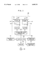
- FIG. 2 is a block diagram showing a structure of the back printing section
- FIGS. 3A, 3B and 3C are explanatory illustrations showing an example of back printing
- FIG. 4 is a flow chart showing a changeover program of a typing unit in the case of the one-line typing mode
- FIG. 5 is an explanatory illustration showing an embodiment in which two typing units are rotated.
- FIG. 6 is an explanatory illustration showing another embodiment in which a large ink ribbon cassette is used.
- a color paper 10 is drawn out from the paper roll 11 and transported toward an exposure station 12.
- the color paper 10 is a continuous photographic paper.
- a white light source 13 Above the exposure station 12, there are disposed a white light source 13, a yellow filter 14, a magenta filter 15, and a cyan filter 16.
- a white light source 13 Above the exposure station 12, there are disposed a white light source 13, a yellow filter 14, a magenta filter 15, and a cyan filter 16.
- an amount inserted into an optical path is adjusted in accordance with three-color densities of a frame formed on a photographic film 17.
- Printing light regulated by passing through a part of the three-color filters 14, 15 and 16 is diffused by a diffusion box 18.
- the frame of the photographic film 17 is set under the diffusion box 18.
- the printing light passing through the frame is projected to the color paper 10 via a print lens 19 while a shutter 20 is opened.
- a transparent magnetic recording layer is formed on a whole rear face of the photographic film 17. Both sides of the magnetic recording layer excepting a picture portion are used as two tracks. One of the tracks is for a user and the other of the tracks is for a photofinishing laboratory. In a side portion (a frame exclusive portion) of each frame relative to each track, various information regarding the frame is magnetically recorded. In a leader portion (a common portion), common information regarding each frame is recorded.
- a film manufacturer In the common portion of the track for the user, a film manufacturer, a kind of a film, film sensitivity, a photographable number of the film and so forth are recorded when the film is manufactured.
- ID number of the laboratory ID number of the photographic printer, a film order number and so forth are recorded at the laboratory.
- a magnetic head 21 reads out the user information of the frame for printing.
- the magnetic head for recording the laboratory information is omitted.
- Reference numerals 22 and 23 denote a mask plate.
- the color paper 10 passing through the exposure station 12 is sent to a back printing section 28 via a transporting roller pair 26 and a guide roller 27.
- a back printing section 28 one-line typing mode for typing by one line is selected in case of 135-type photographic film, and two-line typing mode for typing by two lines is selected in case of IX240-type photographic film.
- the color paper 10 for which back printing has been carried out is sent to a processor section 31 via a transporting roller pair 29 and a guide roller 30.
- the processor section 31 carries out a developing process, a bleach-fix process, a washing process, a drying process and so forth. After that, the processor section 31 cuts away a photo print 32 and discharges it to a tray 33.
- a motor 36 is driven to rotate the transporting roller pairs 26 and 29 whenever one printing exposure is over. These transporting roller pairs 26 and 29 transport the color paper 10 frame by frame.
- the back printing section 28 is provided with two typing units 40 and 41.
- the typing units 40 and 41 are constituted of typing heads 42 and 43 of wire dot type, and ink ribbon cassettes 44 and 45 of endless type.
- an ink ribbon 46 which is a cloth including ink, is contained in a state that the ink ribbon 46 is wound around a reel.
- each of the typing heads 42 and 43 a plurality of pins are disposed in matrix as well known.
- the pin protrudes selectively according to a character being typed and strikes the back of the ink ribbon 46.
- the ink ribbon 46 is struck in a state that the ink ribbon 46 is superimposed on the color paper 10 so that the ink is transferred to the color paper 10 and the character represented by dot pattern is typed.
- Each of the typing units 40 and 41 is fixed and activated to type the characters one by one every time the color paper 10 moves by prescribed pitch.
- the typing units 40 and 41 may be movable in moving direction of the color paper 10. At this time, the typing units 40 and 41 are moved to type the characters one by one in order while the color paper 10 is stopped.
- a plurality of pins may be disposed in a row to type the character by activating each of the pins at plural times, moving the color paper 10. In case of this typing unit, typing speed is slow, however, the structure is simple because the number of the pins is small.
- Drivers 50 and 51 drive the typing heads 42 and 43 respectively in accordance with character data outputted from a character data generator 52.
- a character data generator 52 typing information outputted from a controller 53 is inputted.
- the typing information includes the film order number, the frame number, the exposure correction value and so forth.
- the user information read out with the magnetic head 21 is also sent to the character data generator 52 via the controller 53.
- the back printing section 28 is constituted of the character data generator 52, the drivers 50 and 51, and the typing units 40 and 41.
- the controller 53 sends a typing timing signal synchronizing with advancement of the color paper 10, a kind of the typing mode, an instruction for replacing the typing unit, and so forth to the character data generator 52 besides the typing information of the frame number, the exposure correction value and so on.
- the typing unit is changed every one order (every one photographic film), however, the typing unit may be changed every plural orders or every printing. In other words, the typing unit may be changed every predetermined number of the photo prints. Alternatively, the typing unit may be changed every prescribed period, for example, each day.
- the controller 53 controls a rotation of the motor 36 via a driver 54. Further, the controller 53 controls the processor section 31 and a printing section 55.
- the printing section 55 is a section for exposing the frame of the photographic film 17 to the color paper 10 and comprises the white light source 13, the three-color filters 14-16, the print lens 19 and the shutter 20 which are shown in FIG. 1.
- FIGS. 3A to 3C show back printing.
- the order number of the photographic film, the frame number of the photographic film, the exposure correction value and so forth are typed for the back face of photo prints 32a and 32b as one line.
- Reference numerals 58 and 59 respectively denote one line typed by the typing unit.
- the message, the photographic date, the photographic condition, the order number of the photographic film, the frame number of the photographic film, the exposure correction value, the ID-number of the laboratory and so forth are typed for the back face of a photo print 32c as two lines.
- Reference numerals 60a and 60b respectively denote each line typed by the typing units.
- the film carrier for the 135-type photographic film is set on the work table.
- the controller 53 is instructed to print the 135-type photographic film.
- the controller 53 instructs the character data generator 52 to take the one-line typing mode.
- the film carrier sets the frame for printing on the mask plate 22 by advancing the photographic film.
- photometry for the frame is carried out by a LATD sensor (not shown) and average densities concerning each color of red, green and blue is measured. From the average densities of three colors, basic exposure is calculated. Further, the frame of the photographic film is scanned by a scanner (not shown). The exposure correction value of each color is calculated from the obtained three-color densities of each point. The exposure correction value is added to the basic exposure and the exposure of each color is calculated.
- the controller 53 regulates the printing light in accordance with the exposure of each color by adjusting an amount of the three-color filters 14, 15 and 16 inserted into the optical path.
- the regulated printing light is diffused with the diffusion box 18 and illuminates the frame for printing.
- the shutter 20 is opened by predetermined time to print an image of the frame on the color paper 10.
- the controller 53 rotates the motor 36 to advance the color paper 10 by one frame.
- the film carrier is operated to advance the photographic film by one frame so that the next frame is set on the mask plate 22. As described above, photometry of the frame, regulation of the light and printing are carried out. These steps are repeated and each frame of the photographic film is printed. After the printing of one photographic film was over, another photographic film is set on the film carrier and the printing is similarly performed.
- the controller 53 sends the typing information to the character data generator 52. Further, the controller 53 sends the typing timing signal synchronizing with the rotation of the motor 36 to the character data generator 52.
- the character data generator 52 When the character data generator 52 receives the typing timing signal, the character data generator 52 drives, for example, the typing head 42 via the driver 50 so that the ink of the ink ribbon 46 is transferred to the back face of the color paper 10, Accordingly, one character represented by a dot pattern is recorded. In such a manner, the typing unit 40 types one line character by character in synchronism with advancement of the color paper 10. The typing of one line is carried out corresponding to each picture exposed on the color paper 10.
- the color paper 10 is cut into one photo print 32a and discharged to the tray 33.
- the photo print 32a the order number of the photographic film, the frame number, the exposure correction value and so forth are typed in one line as shown in FIG. 3A.
- the controller 53 instructs the character data generator 52 to change the typing unit.
- the character data generator 52 rests the typing head 42 and drives the typing head 43 instead of the typing head 42.
- the back printing is carried out line by line for each picture.
- the information of one line is typed on an under portion of the back face of the photo print 32b as shown in FIG. 3B.
- the film carrier for IX240 is set on the work table.
- the cartridge is set on the film carrier.
- the controller 53 instructs the character data generator 52 to take the two-line typing mode.
- the film carrier rotates the spool of the cartridge to send out a leader of the photographic film.
- the film leader is advanced toward the exposure station 12, being nipped by a pair of transporting rollers.
- the common information of the film sensitivity, the photograph number and so forth are read out from the common portion of the track for the user by means of the magnetic head 21.
- the ID number of the laboratory, the ID number of the photographic printer and so on are recorded in the common portion of the track for the laboratory.
- the frame is recorded between two perforations.
- the frame for printing is set on the exposure station 12 by detecting the perforation with a photo sensor during advancement of the photographic film.
- the user information of the photographic date, the photographic condition, the print number, the print size, the message and so forth are read out from the frame exclusive portion of the track for the user with the magnetic head 21. The user information is sent to the controller 53.
- the controller 53 adjusts an advancing amount of the color paper 10 in accordance with the designated print size. Further, the controller 53 adjusts the size of the mask plate 23 and a printing magnification of the print lens 19.
- the frame set on the exposure station 12 photometry for an area corresponding to the print size is carried out and the exposures of three colors are calculated on the basis of the photometric value. Insert positions of the color filters 14, 15 and 16 are respectively adjusted in accordance with the exposure of each color. Then, the shutter 20 is opened to expose and print the color paper 10.
- the controller 53 rotates the motor 36 to advance the color paper 10 by one frame.
- the film carrier rotates the transporting roller pair to transport the photographic film 17. During this transportation, the exposure correction value and so forth are recorded in the frame exclusive portion of the track for the laboratory with a magnetic head (not shown).
- each frame recorded in the photographic film is printed on the color paper 10 in order.
- the transporting roller pair of the film carrier and the spool of the cartridge are rotated in reverse direction so that all of the photographic film is wound back into the cartridge.
- the cartridge is exchanged to another cartridge and the printing is performed in a similar process.
- the controller 53 instructs the character data generator 52 to print the character. After this instruction, the typing timing signal is sent to the character data generator 52 in synchronism with the rotation of the motor 36.
- the character data generator 52 When the character data generator 52 receives the typing timing signal, the character data generator 52 drives the typing heads 42 and 43 via the drivers 50 and 51 respectively to transfer the ink of the ink ribbon 46 to the back face of the color paper 10. Accordingly, one character represented by a dot pattern is recorded. In such a manner, the typing units 40 and 41 print each line character by character in synchronism with the advancement of the color paper 10.
- the photographic processes are carried out. After that, the color paper 10 is cut into a photo print 32c and the photo print 32c is discharged to the tray 33.
- the photo print 32c the message, the photographic date, the photographic condition, the order number of the photographic film, the frame number of the photographic film, the exposure correction value, ID number of the laboratory and so forth are typed on the back face thereof in two lines as shown in FIG. 3C.
- Each of the typing units 40 and 41 is alternately used in the one-line printing mode so that decreasing states of the ink ribbons become similar to each other. Accordingly, in the two-line typing mode, typing density of one line is not different from the other. Moreover, the two ink ribbon cassettes 40 and 41 are exchanged together when the typing density becomes light.
- the two typing units 40 and 41 are alternately used every photographic film so that print positions are same relative to photo prints corresponding to one photographic film. However, when the user orders the photo prints of two photographic films, the print positions are different relative to each photographic film. In order to keep same print position, the two typing units may be rotated or slid to replace the position thereof.
- two typing units 63 and 64 are attached to a holder 62.
- the holder 62 is a table and the typing units 63 and 64 are disposed at a same distance from a rotational center of the table.
- a motor 65 is driven to rotate the holder 62 by 180 degrees so that positions of the two typing units are replaced.
- the typing unit being driven is changed so that the information of one line is typed at the same position of the photo prints.
- FIG. 6 shows an embodiment in that a larger ink ribbon cassette 69 is employed such as to surround two typing heads 67 and 68 which are disposed along a perpendicular direction to a moving direction of the color paper 10, namely photo print.
- An ink ribbon 70 drawn out from the ink ribbon cassette 69 passes by the printing heads 67 and 68 in order and is wound up into the cassette again.
- the one-line typing mode one of the typing heads is always used.
- two typing heads 67 and 68 are used. In this embodiment, only one of the typing heads is used in the one-line typing mode.
- the ink ribbon is used in common, when the typing mode is exchanged to the two-line typing mode, difference of the printing density does not occur between each of lines.
- the back printing is carried out on the rear face of the photo print.
- the present invention is available for front printing in which the typing is carried out on an image face of the photo print, for example, on a white rim or a white portion.
- plural-line typing for example, three-line typing and four-line typing
- one-line typing may be selectively performed.
- three typing units or three typing heads are used. At this time, the three typing units are alternately used in order in the one-line typing mode.
- the number of typing lines may be determined in accordance with an amount of information being typed.
- the photographic paper is a continuous photographic paper.
- a sheet cut paper having a prescribed size may be used instead of the continuous photographic paper.
Abstract
Description
Claims (12)
Applications Claiming Priority (2)
| Application Number | Priority Date | Filing Date | Title |
|---|---|---|---|
| JP8-244818 | 1996-09-17 | ||
| JP24481896A JP3745841B2 (en) | 1996-09-17 | 1996-09-17 | Photo printer printing method and apparatus |
Publications (1)
| Publication Number | Publication Date |
|---|---|
| US6050733A true US6050733A (en) | 2000-04-18 |
Family
ID=17124414
Family Applications (1)
| Application Number | Title | Priority Date | Filing Date |
|---|---|---|---|
| US08/931,494 Expired - Fee Related US6050733A (en) | 1996-09-17 | 1997-09-16 | Typing method for a photographic printer and typing device for the same |
Country Status (2)
| Country | Link |
|---|---|
| US (1) | US6050733A (en) |
| JP (1) | JP3745841B2 (en) |
Cited By (2)
| Publication number | Priority date | Publication date | Assignee | Title |
|---|---|---|---|---|
| US6561705B2 (en) * | 2001-02-16 | 2003-05-13 | Eastman Kodak Company | Photo-finishing |
| US6646754B1 (en) * | 1999-08-31 | 2003-11-11 | Shutterfly, Inc. | Backprinting image prints |
Citations (5)
| Publication number | Priority date | Publication date | Assignee | Title |
|---|---|---|---|---|
| US4481880A (en) * | 1980-10-06 | 1984-11-13 | Hitachi Koki Company Limited | Dot printer |
| US4576490A (en) * | 1983-12-14 | 1986-03-18 | Oki Electric Industry Co., Ltd. | Multihead serial printer |
| US4684269A (en) * | 1984-08-21 | 1987-08-04 | Brother Kogyo Kabushiki Kaisha | Apparatus for printing with character fonts and dot-matrix printing in the same line |
| US5330274A (en) * | 1989-03-08 | 1994-07-19 | Siemens Nixdorf Informationssysteme Aktiengesellschaft | Printing device having at least two printing stations separated spatially from one another |
| US5336873A (en) * | 1988-12-05 | 1994-08-09 | Fuji Photo Film Co., Ltd. | Photographic film having frame number bar codes |
-
1996
- 1996-09-17 JP JP24481896A patent/JP3745841B2/en not_active Expired - Fee Related
-
1997
- 1997-09-16 US US08/931,494 patent/US6050733A/en not_active Expired - Fee Related
Patent Citations (5)
| Publication number | Priority date | Publication date | Assignee | Title |
|---|---|---|---|---|
| US4481880A (en) * | 1980-10-06 | 1984-11-13 | Hitachi Koki Company Limited | Dot printer |
| US4576490A (en) * | 1983-12-14 | 1986-03-18 | Oki Electric Industry Co., Ltd. | Multihead serial printer |
| US4684269A (en) * | 1984-08-21 | 1987-08-04 | Brother Kogyo Kabushiki Kaisha | Apparatus for printing with character fonts and dot-matrix printing in the same line |
| US5336873A (en) * | 1988-12-05 | 1994-08-09 | Fuji Photo Film Co., Ltd. | Photographic film having frame number bar codes |
| US5330274A (en) * | 1989-03-08 | 1994-07-19 | Siemens Nixdorf Informationssysteme Aktiengesellschaft | Printing device having at least two printing stations separated spatially from one another |
Cited By (2)
| Publication number | Priority date | Publication date | Assignee | Title |
|---|---|---|---|---|
| US6646754B1 (en) * | 1999-08-31 | 2003-11-11 | Shutterfly, Inc. | Backprinting image prints |
| US6561705B2 (en) * | 2001-02-16 | 2003-05-13 | Eastman Kodak Company | Photo-finishing |
Also Published As
| Publication number | Publication date |
|---|---|
| JPH1090805A (en) | 1998-04-10 |
| JP3745841B2 (en) | 2006-02-15 |
Similar Documents
| Publication | Publication Date | Title |
|---|---|---|
| JP2658733B2 (en) | Image synthesis printer | |
| US5452050A (en) | Image printer | |
| US5978067A (en) | Photographic camera system | |
| EP0561592B1 (en) | Photographic film printer | |
| US6050733A (en) | Typing method for a photographic printer and typing device for the same | |
| US6078757A (en) | Photographic camera system | |
| JP3665121B2 (en) | Index print exposure method and index printer | |
| US4916479A (en) | Photographic printer-processor | |
| JP2658732B2 (en) | Image synthesis printer | |
| JPH0829884A (en) | Photograph printing device | |
| JP3541347B2 (en) | Photographic system and photographic film printing device | |
| JP4258082B2 (en) | Photo processing apparatus and photo processing method | |
| JP3603218B2 (en) | Photographic system and photographic film printing device | |
| US5717975A (en) | Method of and apparatus for the production of photographic proofs | |
| JP2511513B2 (en) | Photosynthesis printing equipment | |
| JP3476596B2 (en) | Image printing method | |
| JP2641772B2 (en) | Photo synthesis printing method | |
| JPH1073887A (en) | Film copying on various kinds of conditions | |
| JP2001133900A (en) | Photographic processing device | |
| JPH04213447A (en) | Frame number printing method for autoprinter | |
| JPH02311836A (en) | Illustrated image test printing device for photograph composite printer | |
| JPH0968760A (en) | Image compositing printer | |
| JPH0993421A (en) | Image processor | |
| JPH04269748A (en) | Information reading method and information writing device for photographic film | |
| JP2002202568A (en) | Image printer |
Legal Events
| Date | Code | Title | Description |
|---|---|---|---|
| AS | Assignment |
Owner name: FUJI PHOTO FILM CO., LTD., JAPAN Free format text: ASSIGNMENT OF ASSIGNORS INTEREST;ASSIGNOR:YAMAMOTO, TAKASHI;REEL/FRAME:008718/0703 Effective date: 19970905 |
|
| FPAY | Fee payment |
Year of fee payment: 4 |
|
| AS | Assignment |
Owner name: FUJIFILM CORPORATION, JAPAN Free format text: ASSIGNMENT OF ASSIGNORS INTEREST;ASSIGNOR:FUJIFILM HOLDINGS CORPORATION (FORMERLY FUJI PHOTO FILM CO., LTD.);REEL/FRAME:018904/0001 Effective date: 20070130 Owner name: FUJIFILM CORPORATION,JAPAN Free format text: ASSIGNMENT OF ASSIGNORS INTEREST;ASSIGNOR:FUJIFILM HOLDINGS CORPORATION (FORMERLY FUJI PHOTO FILM CO., LTD.);REEL/FRAME:018904/0001 Effective date: 20070130 |
|
| FPAY | Fee payment |
Year of fee payment: 8 |
|
| FEPP | Fee payment procedure |
Free format text: PAYOR NUMBER ASSIGNED (ORIGINAL EVENT CODE: ASPN); ENTITY STATUS OF PATENT OWNER: LARGE ENTITY |
|
| REMI | Maintenance fee reminder mailed | ||
| LAPS | Lapse for failure to pay maintenance fees | ||
| STCH | Information on status: patent discontinuation |
Free format text: PATENT EXPIRED DUE TO NONPAYMENT OF MAINTENANCE FEES UNDER 37 CFR 1.362 |
|
| FP | Lapsed due to failure to pay maintenance fee |
Effective date: 20120418 |