US6038356A - Lightwave transmission system employing raman and rare-earth doped fiber amplification - Google Patents
Lightwave transmission system employing raman and rare-earth doped fiber amplification Download PDFInfo
- Publication number
- US6038356A US6038356A US08/937,896 US93789697A US6038356A US 6038356 A US6038356 A US 6038356A US 93789697 A US93789697 A US 93789697A US 6038356 A US6038356 A US 6038356A
- Authority
- US
- United States
- Prior art keywords
- optical
- optical fiber
- signal
- optical signal
- amplifiers
- Prior art date
- Legal status (The legal status is an assumption and is not a legal conclusion. Google has not performed a legal analysis and makes no representation as to the accuracy of the status listed.)
- Expired - Lifetime
Links
Images

Classifications
-
- H—ELECTRICITY
- H04—ELECTRIC COMMUNICATION TECHNIQUE
- H04B—TRANSMISSION
- H04B10/00—Transmission systems employing electromagnetic waves other than radio-waves, e.g. infrared, visible or ultraviolet light, or employing corpuscular radiation, e.g. quantum communication
- H04B10/29—Repeaters
- H04B10/291—Repeaters in which processing or amplification is carried out without conversion of the main signal from optical form
- H04B10/293—Signal power control
- H04B10/2933—Signal power control considering the whole optical path
- H04B10/2935—Signal power control considering the whole optical path with a cascade of amplifiers
-
- H—ELECTRICITY
- H04—ELECTRIC COMMUNICATION TECHNIQUE
- H04B—TRANSMISSION
- H04B10/00—Transmission systems employing electromagnetic waves other than radio-waves, e.g. infrared, visible or ultraviolet light, or employing corpuscular radiation, e.g. quantum communication
- H04B10/29—Repeaters
- H04B10/291—Repeaters in which processing or amplification is carried out without conversion of the main signal from optical form
- H04B10/2912—Repeaters in which processing or amplification is carried out without conversion of the main signal from optical form characterised by the medium used for amplification or processing
- H04B10/2916—Repeaters in which processing or amplification is carried out without conversion of the main signal from optical form characterised by the medium used for amplification or processing using Raman or Brillouin amplifiers
Definitions
- This invention relates to the optical transmission of information, and more particularly, to a lightwave transmission system employing Raman and rare earth doped amplification.
- Lightwave communication systems use optical amplifiers to carry large amounts of multiplexed data over long distances from a transmit terminal to a receive terminal.
- the maximum distance that the data can be transmitted in the fiber without amplification or regeneration is limited by, among other things, loss associated with the optical fiber.
- the lightwave systems may include a number of optical amplifiers periodically located along the fiber route from the transmit terminal to the receive terminal. Each optical amplifier boosts the received signal to compensate for transmission losses which occurred since the last repeater.
- Optical amplifiers are attractive alternatives to other amplifier forms because they amplify lightwave signals in their optical form without conversion into a corresponding electrical signal. Each such optical amplifier is pumped, either optically or electrically, to provide signal amplification.
- One optical amplifier realization that is commonly employed in lightwave communication systems is rare-earth doped optical fiber amplifiers.
- One desirable feature of such amplifiers is the automatic gain control they provide when operating in saturation.
- one disadvantage of such amplifiers is that they yield undesirably high noise levels.
- a Raman amplifier which is another optical amplifier realization, offers potentially lower noise levels but does not easily provide the gain control.
- Doped fiber amplifiers that are pumped by a remotely located optical pump source via the transmission path are known. In such systems Raman amplification also occurs as the pump energy traverses the transmission path.
- remotely pumped systems are used in short-haul, unrepeatered lightwave transmission systems and hence automatic gain control in the amplifiers is not a concern. Accordingly, such systems do not take advantage of the full benefits offered by doped optical amplifiers operating in saturation.
- a method for transmitting an optical signal in an optical communication system.
- the system includes a transmitter for generating the optical signal, a receiver for detecting the signal, and an optical fiber communication link interposed between the transmitter and receiver.
- the optical fiber communication link includes transmission optical fibers concatenated with a plurality of Raman amplifiers and at least one rare earth doped optical fiber amplifier.
- the method includes the steps of: amplifying the optical signal as it advances through each of the plurality of Raman amplifiers; and compensating for variations in transmission path losses to restore the optical signal to a nominal power level as it advances through the rare earth doped optical fiber amplifier by maintaining the doped optical fiber amplifier in its saturated state.
- the present invention utilizes the benefits of both Raman amplifiers and doped fiber amplifiers since the Raman amplifiers impart gain (and hence low noise) while the doped fiber amplifiers provide power stability.
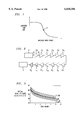
- FIG. 1 shows the gain characteristics of a rare earth doped optical fiber amplifier.
- FIG. 2 shows an exemplary optical communication system operating in accordance with the present invention.
- FIG. 3 shows the signal to noise evolution of a probe signal traversing the system shown in FIG. 2.
- Long distance lightwave communication systems require amplifiers for boosting optical signal levels sufficiently to compensate for losses experienced along the fiber transmission medium.
- Two classes of amplifiers are known, namely, lumped amplifiers and distributed amplifiers.
- An exemplary lumped amplifier is the rare earth doped fiber amplifier, which offers substantial benefits because of its simplicity, low cost, and connective compatibility with existing optical fibers.
- For an exemplary locally pumped, rare-earth doped, fiber amplifier see Electron. Lett., Vol. 23, No. 19, pp. 1026 et seq. (1987). These amplifiers linearly increase optical signal power of a supplied input signal via stimulated emission of fiber dopants such as erbium that is subject to an optical pump source.
- Doped fiber amplifiers are also advantageous in communication systems when operating in a state of saturation because of the power stability they offer. In saturation, the amplifiers regulate the optical power of the signals propagating through the transmission path. A series of fiber amplifiers compensates for system degradations through a process of automatic gain adjustment. The characteristics of doped fiber amplifiers is shown in FIG. 1. The figure shows the small signal gain as a function of input signal power. For an operating point in the saturation region, such as point 22, amplifier gain increases if the average amplifier input power decreases. Likewise, the gain decreases if the average amplifier input power increases. Thus, the gain of optical amplifiers operating in saturation self-adjusts to variations in input power.
- Distributed amplifiers include Raman amplifiers in which amplification is based on stimulated Raman scattering.
- Raman gain is generated by direct optical pumping of the transmission fiber and hence such amplifiers provide distributed amplification over an extended portion of the transmission path, often on a substantially uniform basis.
- An advantage of Raman amplifiers over doped fiber amplifiers is that practically realizable Raman amplifiers are capable of achieving actual noise figures closer to the theoretical optimum value.
- one limitation of Raman amplifiers is that they incur significant system penalties when operating in a state of saturation and thus cannot easily provide the power stability of doped fiber amplifiers. This factor, among others, has limited the applicability of Raman amplifiers in very long distance optical communication systems such as undersea communication systems.
- an optical transmission system such as a long-haul undersea communication system which utilizes both Raman amplification and doped fiber amplification. More specifically, Raman amplification is employed as the gain mechanism that compensates for losses in the transmission path while the doped fiber amplifiers are primarily employed not to impart gain, but to provide stabilization of the signal power. That is, the present invention utilizes the benefits of both Raman and doped fiber amplification while avoiding the deficiencies inherent in each process individually. The resulting transmission system achieves a lower level of total noise (through the use of Raman amplification as the gain mechanism) with adequate power stability (through the use of the doped fiber amplifiers operating in saturation).
- the gain provided by the doped fiber amplifiers is substantially equal to zero, in other embodiments the doped fiber amplifiers impart nonzero gain that is used to compensate for losses in additional system components such as optical filters used to flatten the end to end system gain as a function of wavelength.
- the power evolution is actively controlled by measuring the signal power at each point where Raman pumping is supplied and using a feedback loop to control the pump power so that the desired signal power level is attained. Accordingly, in this embodiment the doped fiber amplifiers are not required. This arrangement would be particularly useful when pumping is performed in the counterpropagating direction (i.e., when the pump power travels in a direction opposite to the signal).
- such active power control elements could be located at intervals less frequent than every pump site.
- the active power control elements could be incorporated into certain repeater bottles which house the Raman pumps in long haul systems.
- the repeaters incorporating the active power control elements may then be spaced at intervals of every five to standard ten repeaters (i.e., those not using the active power control elements).
- FIG. 2 An exemplary optical communications system that was employed to demonstrate the features of the present invention is shown in FIG. 2, wherein 10 is an optical fiber transmission path, 11 is a transmitter of an optical signal, 12 is a receiver for detecting the optical signal, 13 1 , 13 2 , . . . 13 11 are Raman amplifiers disposed along the optical fiber path 10, and 14 1 and 14 2 are erbium doped fiber amplifiers (EDFAs) located in the transmission path between Raman amplifier 13 11 and the receiver 12.
- EDFAs erbium doped fiber amplifiers
- Spans 1-5 and 7-11 comprised 45 km sections of dispersion shifted fiber (-2.6 ps/km-nm average dispersion).
- the system was operated in a circulating loop fashion with a total path length of 7,000 km.
- the pump source was a cascaded Raman laser operating at 1452 nm with a power of 235-308 nW.
- Raman amplifier 13 6 which provided dispersion compensation, was based on 62 km conventional single mode fiber (+17 ps/km-nm), requiring a pump power of 630 nW.
- EDFAs 141 and 142 provided both power level control and additional gain.
- FIG. 3 shows the signal to noise (SNR) evolution of a 1.8 dBM, 1550 nm probe signal traversing the 514 km amplifier chain.
- the lines are calculation based on linear noise theory for concatenated amplifiers and open squares are measurements from the transmission system.
- the figure illustrates that the performance of the amplifiers asymptotically approached the performance of a chain of Raman amplifiers with a 9 dB noise figure for each individual amplifier.
- Line 40 shows the performance of ideal series of EDFAs with 3 dB noise figures spaced 45 km apart.
- the optical SNR of the Raman chain of amplifiers is 3.5 dB better than that of the EDFA chain, assuming equal launch powers. This translates to a 1.5 dB improvement in performance, assuming equal path-averaged power.
Landscapes
- Physics & Mathematics (AREA)
- Electromagnetism (AREA)
- Engineering & Computer Science (AREA)
- Computer Networks & Wireless Communication (AREA)
- Signal Processing (AREA)
- Optical Communication System (AREA)
- Lasers (AREA)
Abstract
Description
Claims (5)
Priority Applications (1)
| Application Number | Priority Date | Filing Date | Title |
|---|---|---|---|
| US08/937,896 US6038356A (en) | 1997-09-25 | 1997-09-25 | Lightwave transmission system employing raman and rare-earth doped fiber amplification |
Applications Claiming Priority (1)
| Application Number | Priority Date | Filing Date | Title |
|---|---|---|---|
| US08/937,896 US6038356A (en) | 1997-09-25 | 1997-09-25 | Lightwave transmission system employing raman and rare-earth doped fiber amplification |
Publications (1)
| Publication Number | Publication Date |
|---|---|
| US6038356A true US6038356A (en) | 2000-03-14 |
Family
ID=25470541
Family Applications (1)
| Application Number | Title | Priority Date | Filing Date |
|---|---|---|---|
| US08/937,896 Expired - Lifetime US6038356A (en) | 1997-09-25 | 1997-09-25 | Lightwave transmission system employing raman and rare-earth doped fiber amplification |
Country Status (1)
| Country | Link |
|---|---|
| US (1) | US6038356A (en) |
Cited By (27)
| Publication number | Priority date | Publication date | Assignee | Title |
|---|---|---|---|---|
| US6147796A (en) * | 1999-01-12 | 2000-11-14 | Tyco Submarine Systems Ltd. | Method for determining transmission parameters for the data channels of a WDM optical communication system |
| US6236487B1 (en) * | 1998-07-21 | 2001-05-22 | Corvis Corporation | Optical communication control system |
| US6323993B1 (en) * | 1999-02-19 | 2001-11-27 | Lucent Technologies Inc. | Method of optical signal transmission with reduced degradation by non-linear effects |
| WO2002030018A2 (en) * | 2000-08-31 | 2002-04-11 | Ciena Corporation | Hybrid amplifier that minimizes noise figure for a particular fibre span loss |
| US6384962B1 (en) | 2000-06-07 | 2002-05-07 | Tycom (Us) Inc. | Method and apparatus to perform automatic gain equalization using raman amplifiers |
| US6396623B1 (en) | 2000-12-19 | 2002-05-28 | Onetta, Inc. | Wide-band optical amplifiers with interleaved gain stages |
| US6433922B1 (en) | 2001-02-26 | 2002-08-13 | Redc Optical Networks Ltd. | Apparatus and method for a self adjusting Raman amplifier |
| US6452715B1 (en) | 2000-08-29 | 2002-09-17 | Ciena Corporation | Method and apparatus for determining a fiber plant gain transfer function and utilizing same to control distributed gain |
| US6456425B1 (en) | 2000-06-07 | 2002-09-24 | Tyco Telecommunications (Us) Inc. | Method and apparatus to perform lumped raman amplification |
| US20020159133A1 (en) * | 2001-02-02 | 2002-10-31 | The Furukawa Electric Co., Ltd. | Pump light source for raman amplifier and raman amplifier using the same |
| US6490077B1 (en) | 2000-11-20 | 2002-12-03 | Corning Incorporated | Composite optical amplifier |
| US20030063373A1 (en) * | 2000-01-14 | 2003-04-03 | The Furukawa Electric Co., Ltd. | Raman amplifier |
| WO2003030203A1 (en) * | 2001-10-03 | 2003-04-10 | Corvis Corporation | Repeater housing for undersea optical communication system |
| WO2003052464A2 (en) * | 2001-12-13 | 2003-06-26 | Corvis Corporation | Raman amplifiers operating in saturation |
| US20030179440A1 (en) * | 2002-03-15 | 2003-09-25 | Dmitri Foursa | Hybrid raman/erbium-doped fiber amplifier and transmission system with dispersion map |
| US6633697B2 (en) | 1999-05-31 | 2003-10-14 | Ther Furukawa Electric Co., Ltd. | Raman amplification method and optical signal transmission method using same |
| EP1416653A2 (en) * | 2002-10-31 | 2004-05-06 | Nec Corporation | Optical transmission system comprising a plurality of optical amplification relay sections |
| US6751421B1 (en) * | 1999-08-10 | 2004-06-15 | Lucent Technologies Inc. | Optical fiber communication system employing wavelength converter for broadband transmission |
| US6775057B2 (en) | 1998-07-23 | 2004-08-10 | The Furukawa Electric Co., Ltd. | Raman amplifier, optical repeater, and raman amplification method |
| US20040156605A1 (en) * | 2003-02-11 | 2004-08-12 | Gleason Robert F. | Method of repairing a slope-matched cable system and replacement cable portion for use therein |
| US20050019039A1 (en) * | 2002-12-12 | 2005-01-27 | Corvis Corporation | System and method for optimized transmission in distributed Raman amplified systems operating in saturation |
| US20050031274A1 (en) * | 2003-08-07 | 2005-02-10 | Rong Zhu | Deployable optical fiber transmission lines, optical transmission cable, and method of making same |
| US20050046929A1 (en) * | 1998-07-21 | 2005-03-03 | Corvis Corporation | Optical transmission systems including signal varying devices and methods |
| US20050213985A1 (en) * | 1999-05-24 | 2005-09-29 | Corvis Corporation | Optical transmission systems including optical amplifiers and methods of use therein |
| US20060133822A1 (en) * | 2004-12-22 | 2006-06-22 | Massimo Manna | Optical transmission system including repeatered and unrepeatered segments |
| US20080074734A1 (en) * | 2006-09-21 | 2008-03-27 | Morten Nissov | System and Method for Gain Equalization and Optical Communication System Incorporating the Same |
| CN105515649A (en) * | 2014-10-14 | 2016-04-20 | 中国移动通信集团山东有限公司 | Optical cable performance detection method and device |
Citations (3)
| Publication number | Priority date | Publication date | Assignee | Title |
|---|---|---|---|---|
| US5905825A (en) * | 1996-03-18 | 1999-05-18 | Alcatel Submarine Networks | Optical transmission method and system using solitons |
| US5943147A (en) * | 1994-11-25 | 1999-08-24 | Pirelli Cavi S.P.A. | Telecommunication system and method for wavelength-division multiplexing transmissions with a controlled separation of the outgoing channels and capable of determining the optical signal/noise ratio |
| US5946117A (en) * | 1994-12-16 | 1999-08-31 | Pirelli Cavi S.P.A. | Optical soliton telecommunication system with dispersion-shifted optical fibre |
-
1997
- 1997-09-25 US US08/937,896 patent/US6038356A/en not_active Expired - Lifetime
Patent Citations (3)
| Publication number | Priority date | Publication date | Assignee | Title |
|---|---|---|---|---|
| US5943147A (en) * | 1994-11-25 | 1999-08-24 | Pirelli Cavi S.P.A. | Telecommunication system and method for wavelength-division multiplexing transmissions with a controlled separation of the outgoing channels and capable of determining the optical signal/noise ratio |
| US5946117A (en) * | 1994-12-16 | 1999-08-31 | Pirelli Cavi S.P.A. | Optical soliton telecommunication system with dispersion-shifted optical fibre |
| US5905825A (en) * | 1996-03-18 | 1999-05-18 | Alcatel Submarine Networks | Optical transmission method and system using solitons |
Cited By (56)
| Publication number | Priority date | Publication date | Assignee | Title |
|---|---|---|---|---|
| US7046430B2 (en) | 1998-07-21 | 2006-05-16 | Corvis Corporation | Optical transmission systems including signal varying devices and methods |
| US6236487B1 (en) * | 1998-07-21 | 2001-05-22 | Corvis Corporation | Optical communication control system |
| US20050046929A1 (en) * | 1998-07-21 | 2005-03-03 | Corvis Corporation | Optical transmission systems including signal varying devices and methods |
| US7692852B2 (en) | 1998-07-23 | 2010-04-06 | The Furukawa Electric Co., Ltd. | Raman amplifier, optical repeater, and Raman amplification method |
| US9281654B2 (en) | 1998-07-23 | 2016-03-08 | Furukawa Electric Co., Ltd. | Raman amplifier, optical repeater, and Raman amplification method |
| US7548368B2 (en) | 1998-07-23 | 2009-06-16 | The Furukawa Electric Co., Ltd. | Raman amplifier, optical repeater, and raman amplification method |
| US20040190909A1 (en) * | 1998-07-23 | 2004-09-30 | The Furukawa Electric Co., Ltd. | Raman amplifier, optical repeater, and raman amplification method |
| US20110141553A1 (en) * | 1998-07-23 | 2011-06-16 | Furukawa Electric Co., Ltd. | Raman amplifier, optical repeater, and raman amplification method |
| US6775057B2 (en) | 1998-07-23 | 2004-08-10 | The Furukawa Electric Co., Ltd. | Raman amplifier, optical repeater, and raman amplification method |
| US8437074B2 (en) | 1998-07-23 | 2013-05-07 | Furukawa Electric Co., Ltd. | Raman amplifier, optical repeater, and Raman amplification method |
| US20070247701A1 (en) * | 1998-07-23 | 2007-10-25 | The Furukawa Electric Co., Ltd. | Raman amplifier, optical repeater, and raman amplification method |
| US6147796A (en) * | 1999-01-12 | 2000-11-14 | Tyco Submarine Systems Ltd. | Method for determining transmission parameters for the data channels of a WDM optical communication system |
| US6323993B1 (en) * | 1999-02-19 | 2001-11-27 | Lucent Technologies Inc. | Method of optical signal transmission with reduced degradation by non-linear effects |
| US20050213985A1 (en) * | 1999-05-24 | 2005-09-29 | Corvis Corporation | Optical transmission systems including optical amplifiers and methods of use therein |
| US7085042B2 (en) | 1999-05-24 | 2006-08-01 | Corvis Corporation | Optical transmission systems including optical amplifiers and methods of use therein |
| US20050078352A1 (en) * | 1999-05-31 | 2005-04-14 | The Furukawa Electric Co., Ltd. | Raman amplification method and optical signal transmission method using same |
| US6882467B1 (en) | 1999-05-31 | 2005-04-19 | The Furukawa Electric Co., Ltd. | Raman amplification method and optical signal transmission method using the same |
| US6633697B2 (en) | 1999-05-31 | 2003-10-14 | Ther Furukawa Electric Co., Ltd. | Raman amplification method and optical signal transmission method using same |
| US6751421B1 (en) * | 1999-08-10 | 2004-06-15 | Lucent Technologies Inc. | Optical fiber communication system employing wavelength converter for broadband transmission |
| US20030063373A1 (en) * | 2000-01-14 | 2003-04-03 | The Furukawa Electric Co., Ltd. | Raman amplifier |
| US20040051937A1 (en) * | 2000-01-14 | 2004-03-18 | The Furukawa Electric Co., Ltd. | Raman amplifier |
| US6825972B2 (en) | 2000-01-14 | 2004-11-30 | The Furukawa Electric Co., Ltd. | Raman amplifier |
| US20050157379A1 (en) * | 2000-01-14 | 2005-07-21 | The Furukawa Electric Co. Ltd. | Raman amplifier |
| US6882468B2 (en) | 2000-01-14 | 2005-04-19 | The Furukawa Electric Co., Ltd. | Raman amplifier |
| US7050221B2 (en) | 2000-01-14 | 2006-05-23 | The Furukawa Electric Co., Ltd. | Raman amplifier |
| US6384962B1 (en) | 2000-06-07 | 2002-05-07 | Tycom (Us) Inc. | Method and apparatus to perform automatic gain equalization using raman amplifiers |
| US6456425B1 (en) | 2000-06-07 | 2002-09-24 | Tyco Telecommunications (Us) Inc. | Method and apparatus to perform lumped raman amplification |
| US6452715B1 (en) | 2000-08-29 | 2002-09-17 | Ciena Corporation | Method and apparatus for determining a fiber plant gain transfer function and utilizing same to control distributed gain |
| WO2002030018A2 (en) * | 2000-08-31 | 2002-04-11 | Ciena Corporation | Hybrid amplifier that minimizes noise figure for a particular fibre span loss |
| WO2002030018A3 (en) * | 2000-08-31 | 2002-11-21 | Ciena Corp | Hybrid amplifier that minimizes noise figure for a particular fibre span loss |
| US6490077B1 (en) | 2000-11-20 | 2002-12-03 | Corning Incorporated | Composite optical amplifier |
| US6396623B1 (en) | 2000-12-19 | 2002-05-28 | Onetta, Inc. | Wide-band optical amplifiers with interleaved gain stages |
| US20020159133A1 (en) * | 2001-02-02 | 2002-10-31 | The Furukawa Electric Co., Ltd. | Pump light source for raman amplifier and raman amplifier using the same |
| US6950230B2 (en) | 2001-02-02 | 2005-09-27 | The Furukawa Electric Co., Ltd. | Pump light source for Raman amplifier and Raman amplifier using the same |
| US6519082B2 (en) | 2001-02-26 | 2003-02-11 | Redc Optical Networks Ltd. | Apparatus and method for a self-adjusting Raman amplifier |
| US6433922B1 (en) | 2001-02-26 | 2002-08-13 | Redc Optical Networks Ltd. | Apparatus and method for a self adjusting Raman amplifier |
| WO2003030203A1 (en) * | 2001-10-03 | 2003-04-10 | Corvis Corporation | Repeater housing for undersea optical communication system |
| WO2003052464A3 (en) * | 2001-12-13 | 2003-12-24 | Corvis Corp | Raman amplifiers operating in saturation |
| WO2003052464A2 (en) * | 2001-12-13 | 2003-06-26 | Corvis Corporation | Raman amplifiers operating in saturation |
| US7085039B2 (en) | 2002-03-15 | 2006-08-01 | Tyco Telecommunications (Us) Inc. | Hybrid Raman/erbium-doped fiber amplifier and transmission system with dispersion map |
| US20030179440A1 (en) * | 2002-03-15 | 2003-09-25 | Dmitri Foursa | Hybrid raman/erbium-doped fiber amplifier and transmission system with dispersion map |
| EP1416653A2 (en) * | 2002-10-31 | 2004-05-06 | Nec Corporation | Optical transmission system comprising a plurality of optical amplification relay sections |
| EP1416653A3 (en) * | 2002-10-31 | 2004-11-17 | Nec Corporation | Optical transmission system comprising a plurality of optical amplification relay sections |
| US20050019039A1 (en) * | 2002-12-12 | 2005-01-27 | Corvis Corporation | System and method for optimized transmission in distributed Raman amplified systems operating in saturation |
| US6782174B1 (en) | 2003-02-11 | 2004-08-24 | Tyco Telecommunications (Us) Inc. | Method of repairing a slope-matched cable system and replacement cable portion for use therein |
| US20040156605A1 (en) * | 2003-02-11 | 2004-08-12 | Gleason Robert F. | Method of repairing a slope-matched cable system and replacement cable portion for use therein |
| US7058268B2 (en) | 2003-08-07 | 2006-06-06 | Tyco Telecommunications (Us) Inc. | Deployable optical fiber transmission lines, optical transmission cable, and method of making same |
| US20050031274A1 (en) * | 2003-08-07 | 2005-02-10 | Rong Zhu | Deployable optical fiber transmission lines, optical transmission cable, and method of making same |
| US7574140B2 (en) | 2004-12-22 | 2009-08-11 | Tyco Telecommunications (Us) Inc. | Optical transmission system including repeatered and unrepeatered segments |
| US20060133822A1 (en) * | 2004-12-22 | 2006-06-22 | Massimo Manna | Optical transmission system including repeatered and unrepeatered segments |
| EP1829251A4 (en) * | 2004-12-22 | 2011-08-31 | Tyco Electronics Subsea Comm | Optical transmission system including repeatered and unrepeatered segments |
| WO2006069136A3 (en) * | 2004-12-22 | 2007-11-08 | Tyco Telecomm Us Inc | Optical transmission system including repeatered and unrepeatered segments |
| EP1829251A2 (en) * | 2004-12-22 | 2007-09-05 | Tyco Telecommunications (US) Inc. | Optical transmission system including repeatered and unrepeatered segments |
| US7924497B2 (en) * | 2006-09-21 | 2011-04-12 | Tyco Electronics Subsea Communications Llc | System and method for gain equalization and optical communication system incorporating the same |
| US20080074734A1 (en) * | 2006-09-21 | 2008-03-27 | Morten Nissov | System and Method for Gain Equalization and Optical Communication System Incorporating the Same |
| CN105515649A (en) * | 2014-10-14 | 2016-04-20 | 中国移动通信集团山东有限公司 | Optical cable performance detection method and device |
Similar Documents
| Publication | Publication Date | Title |
|---|---|---|
| US6038356A (en) | Lightwave transmission system employing raman and rare-earth doped fiber amplification | |
| EP1091509B1 (en) | Optical amplifier for C and L bands | |
| CA2414951C (en) | Cascaded pumping system and method for producing distributed raman amplification in optical fiber telecommunication systems | |
| US5600481A (en) | Optical fiber amplifier and optical transmission system using the same | |
| US6172803B1 (en) | Optical amplifier and transmission system using the same | |
| US6081366A (en) | Optical fiber communication system with a distributed Raman amplifier and a remotely pumped er-doped fiber amplifier | |
| US6292289B1 (en) | Method, device, and system for transmitting a supervisory optical signal | |
| JP2008066739A (en) | System for amplifying optical signal, transmission system with dispersion map, and erbium doped fiber amplifier (edfa) | |
| US20030076577A1 (en) | Lossless optical transmission link | |
| EP2013648B1 (en) | System and method for implementing a high capacity unrepeatered optical communication system | |
| US6147796A (en) | Method for determining transmission parameters for the data channels of a WDM optical communication system | |
| US6823107B2 (en) | Method and device for optical amplification | |
| US20020191277A1 (en) | Method and apparatus for amplifying an optical signal | |
| CN113810110A (en) | Transmission system based on hybrid fiber amplifier | |
| US7145718B2 (en) | Control method of optical fiber amplifier and optical transmission system | |
| US6888670B2 (en) | Hybrid-type low-noise dispersion compensating optical fiber amplifier | |
| US6603896B1 (en) | Power fiber amplifier with flat gain | |
| KR20040005698A (en) | Light amplification module, light amplifier and optical communication system | |
| US6950232B1 (en) | Gain clamped thulium-doped fiber amplification | |
| US20030231377A1 (en) | System and method for controlling optical amplifier pumps | |
| US7139489B2 (en) | System and method of dispersion compensation in optical communication systems | |
| US6643057B2 (en) | Optical amplifier with reduced non-linear signal impairments by optimum pumping configuration and method for using same | |
| EP1460736A1 (en) | Multiwavelength depolarized raman pumps | |
| KR100269170B1 (en) | Optical amplifier using optical fiber reflector | |
| EP1410537B1 (en) | System and method of dispersion compensation in optical communication systems |
Legal Events
| Date | Code | Title | Description |
|---|---|---|---|
| AS | Assignment |
Owner name: TYCO SUBMARINE SYSTEMS LTD., NEW JERSEY Free format text: ASSIGNMENT OF ASSIGNORS INTEREST;ASSIGNORS:KERFOOT, FRANKLIN W. III;NISSOV, MORTEN;REEL/FRAME:009836/0869 Effective date: 19990322 |
|
| STCF | Information on status: patent grant |
Free format text: PATENTED CASE |
|
| AS | Assignment |
Owner name: TYCOM (US) INC., NEW JERSEY Free format text: CHANGE OF NAME;ASSIGNOR:TYCO SUBMARINE SYSTEMS LTD.;REEL/FRAME:011658/0055 Effective date: 20000725 |
|
| FPAY | Fee payment |
Year of fee payment: 4 |
|
| FEPP | Fee payment procedure |
Free format text: PAYOR NUMBER ASSIGNED (ORIGINAL EVENT CODE: ASPN); ENTITY STATUS OF PATENT OWNER: LARGE ENTITY |
|
| FPAY | Fee payment |
Year of fee payment: 8 |
|
| AS | Assignment |
Owner name: TYCO TELECOMMUNICATIONS (US) INC.,NEW JERSEY Free format text: CHANGE OF NAME;ASSIGNOR:TYCOM (US) INC.;REEL/FRAME:024213/0432 Effective date: 20020105 |
|
| FPAY | Fee payment |
Year of fee payment: 12 |