US6033111A - Color coding method and apparatus for an X-ray positioning system - Google Patents
Color coding method and apparatus for an X-ray positioning system Download PDFInfo
- Publication number
- US6033111A US6033111A US09/196,020 US19602098A US6033111A US 6033111 A US6033111 A US 6033111A US 19602098 A US19602098 A US 19602098A US 6033111 A US6033111 A US 6033111A
- Authority
- US
- United States
- Prior art keywords
- color
- dental
- ray
- positioner
- components
- Prior art date
- Legal status (The legal status is an assumption and is not a legal conclusion. Google has not performed a legal analysis and makes no representation as to the accuracy of the status listed.)
- Expired - Fee Related
Links
- 238000000034 method Methods 0.000 title claims description 58
- 230000008878 coupling Effects 0.000 claims 2
- 238000010168 coupling process Methods 0.000 claims 2
- 238000005859 coupling reaction Methods 0.000 claims 2
- 210000004283 incisor Anatomy 0.000 description 14
- 210000004763 bicuspid Anatomy 0.000 description 13
- 210000003464 cuspid Anatomy 0.000 description 10
- 239000003086 colorant Substances 0.000 description 4
- 238000012986 modification Methods 0.000 description 3
- 230000004048 modification Effects 0.000 description 3
- 210000003484 anatomy Anatomy 0.000 description 2
- 229920000742 Cotton Polymers 0.000 description 1
- 210000004262 dental pulp cavity Anatomy 0.000 description 1
- 238000003745 diagnosis Methods 0.000 description 1
- 238000000605 extraction Methods 0.000 description 1
- 210000003254 palate Anatomy 0.000 description 1
- 238000007493 shaping process Methods 0.000 description 1
- 210000004357 third molar Anatomy 0.000 description 1
Images


Classifications
-
- G—PHYSICS
- G03—PHOTOGRAPHY; CINEMATOGRAPHY; ANALOGOUS TECHNIQUES USING WAVES OTHER THAN OPTICAL WAVES; ELECTROGRAPHY; HOLOGRAPHY
- G03B—APPARATUS OR ARRANGEMENTS FOR TAKING PHOTOGRAPHS OR FOR PROJECTING OR VIEWING THEM; APPARATUS OR ARRANGEMENTS EMPLOYING ANALOGOUS TECHNIQUES USING WAVES OTHER THAN OPTICAL WAVES; ACCESSORIES THEREFOR
- G03B42/00—Obtaining records using waves other than optical waves; Visualisation of such records by using optical means
- G03B42/02—Obtaining records using waves other than optical waves; Visualisation of such records by using optical means using X-rays
- G03B42/04—Holders for X-ray films
- G03B42/042—Holders for X-ray films for dental applications
-
- A—HUMAN NECESSITIES
- A61—MEDICAL OR VETERINARY SCIENCE; HYGIENE
- A61B—DIAGNOSIS; SURGERY; IDENTIFICATION
- A61B6/00—Apparatus or devices for radiation diagnosis; Apparatus or devices for radiation diagnosis combined with radiation therapy equipment
- A61B6/44—Constructional features of apparatus for radiation diagnosis
- A61B6/4429—Constructional features of apparatus for radiation diagnosis related to the mounting of source units and detector units
- A61B6/4435—Constructional features of apparatus for radiation diagnosis related to the mounting of source units and detector units the source unit and the detector unit being coupled by a rigid structure
-
- A—HUMAN NECESSITIES
- A61—MEDICAL OR VETERINARY SCIENCE; HYGIENE
- A61B—DIAGNOSIS; SURGERY; IDENTIFICATION
- A61B6/00—Apparatus or devices for radiation diagnosis; Apparatus or devices for radiation diagnosis combined with radiation therapy equipment
- A61B6/50—Apparatus or devices for radiation diagnosis; Apparatus or devices for radiation diagnosis combined with radiation therapy equipment specially adapted for specific body parts; specially adapted for specific clinical applications
- A61B6/51—Apparatus or devices for radiation diagnosis; Apparatus or devices for radiation diagnosis combined with radiation therapy equipment specially adapted for specific body parts; specially adapted for specific clinical applications for dentistry
- A61B6/512—Intraoral means
-
- A—HUMAN NECESSITIES
- A61—MEDICAL OR VETERINARY SCIENCE; HYGIENE
- A61B—DIAGNOSIS; SURGERY; IDENTIFICATION
- A61B6/00—Apparatus or devices for radiation diagnosis; Apparatus or devices for radiation diagnosis combined with radiation therapy equipment
- A61B6/50—Apparatus or devices for radiation diagnosis; Apparatus or devices for radiation diagnosis combined with radiation therapy equipment specially adapted for specific body parts; specially adapted for specific clinical applications
- A61B6/51—Apparatus or devices for radiation diagnosis; Apparatus or devices for radiation diagnosis combined with radiation therapy equipment specially adapted for specific body parts; specially adapted for specific clinical applications for dentistry
Definitions
- the present invention relates to a color coding method and apparatus and, more particularly, a color coding method and apparatus for an X-ray positioning system.
- the dental X-ray is vital to the diagnosis and treatment of the patient's teeth.
- the dental X-ray provides the dentist with a quick and accurate picture of the patient's teeth with which the dentist initially diagnoses a new patient's teeth and determines the course of treatment which may include root canals, cavity feelings, wisdom teeth extractions, etc. Since the dental X-ray provides the dentist with an interior picture of the teeth, the dentist can determine almost immediately what the condition of the teeth is and what course of action to take in the treatment of the teeth.
- the dental X-ray is so fundamental to the dentist's practice that it is the first thing the dentist requires when treating a new patient.
- Dental X-raying techniques have evolved over the years. The most primitive dental X-ray technique involved the dentist placing a small X-ray film within the patient's mouth and exposing the X-ray film to X-rays from an X-ray machine emitter which was placed proximate to the patient's face such that the X-ray is directed to the X-ray film.
- this object-to-film distance was sizeable in some areas, such as the maxillary molar position where the X-ray film was held in the midline of the palate of the mouth, to achieve this parallelism. This made holding the X-ray film in the patient's mouth difficult while the X-ray film was exposed. Another problem is that the increased object-to-film distance resulted in a loss of image definition, or sharpness.
- the positioner comprises an aiming ring 100 which attaches to the cone 102, an indicator arm 104 which is held by the aiming ring and a bite-block 106 which holds the X-ray film.
- the dentist need only position the film parallel to the teeth and the film, teeth and cone are in alignment such that the film and the teeth are parallel and the cone of the X-ray beam is perpendicular to both.
- positioners do not take into account the different areas of the patient's mouth, known as the four quadrants.
- each of the four quadrants of the patient's mouth requires different types of X-ray films, has different bites and is in different positions of the patient's mouth.
- there are different X-ray films for X-raying different teeth different bite-blocks to receive different bites from the patient's mouth and different indicator arms for positioning the X-ray film in the proper position in the areas of the patient's mouth.
- the aiming ring needed to be modified for different positions in order to properly direct the indicator arm to the desired area of the patient's mouth.
- the present invention provides a color coding method and apparatus for an X-ray positioning system.
- one or more components of the positioning system including a positioning or aiming ring, an indicator arm and bite-block or bite-wing block such that the dentist or dental assistant quickly identifies the correct components for assembling a particular positioner for X-raying a particular dental area.
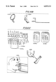
- FIG. 1 illustrates the conventional positioner
- FIGS. 2A and 2B illustrate the color coding method and apparatus of the present invention
- FIGS. 3A-3D illustrate anterior and posterior components of the present invention
- FIGS. 4A-4C illustrate the method for X-raying the maxillary incisor region
- FIGS. 5A-5C illustrate the method for X-raying the maxillary lateral incisor region
- FIGS. 6A-6C illustrate the method for X-raying the maxillary cuspid region
- FIGS. 7A-7C illustrate the method for X-raying the maxillar bicuspid (premolar) region
- FIGS. 8A-8C illustrate the method for X-raying the maxillar molar region
- FIGS. 9A-9C illustrate the method for X-raying the mandibular incisor region
- FIGS. 10A-10C illustrate the method for X-raying the mandibular cuspid region
- FIGS. 11A-11C illustrate the method for X-raying the mandibular bicuspid (premolar) region
- FIGS. 13A-13C illustrate the method for X-raying the interproximal bicuspid (premolar) region
- FIGS. 2A and 2B illustrate two examples of the color coding method and apparatus of the present invention for color coding the components of the dental X-ray. More specifically, FIG. 2A illustrates an interior positioning system wherein the components thereof are color coded for X-raying interior dental areas. In FIG. 2B, a posterior positioner is illustrated with components color coded for X-raying posterior dental areas of the patient. It will be appreciated that the colors chosen may be any combination of colors.
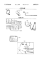
- FIG. 3A illustrates the anterior and posterior aiming rings.
- the anterior aiming ring is constructed with a holding member 300a for holding an anterior arm such that the anterior bite-block and X-ray film thereon are directed to the optimum position and alignment for X-raying the anterior dental area of the patient's teeth.
- the holding member 300a of the anterior aiming ring is directed away from the longitudinal axis of the anterior aiming ring and is extended in the approximate direction of the X-ray beam.
- the posterior aiming ring by contrast, includes a holding member 300b which is constructed for holding a posterior arm at the optimum position such that the posterior bite-block and X-ray film thereon are placed at the optimum position and alignment for X-raying posterior areas of the patient's teeth.
- the holding member 300b is closer to the longitudinal axis of the posterior aiming ring and is truncated in the direction of the X-ray beam as compared with the anterior aiming ring. It will be appreciated that the particular arrangements of the anterior and posterior aiming rings may vary according to the desired dental area to be X-rayed.
- FIG. 3B illustrates the anterior bite-block 302a for holding anterior X-ray films at the anterior of the dental area of the patient's mouth and the posterior bite-block 302b for holding posterior X-ray films at the posterior of the patient's mouth.
- the anterior bite-block is constructed in a more narrow and elongated arrangement which is optimum for X-raying anterior dental areas of the patient's teeth.
- the posterior bite-block is constructed wider and more stout which is optimum for X-raying posterior dental areas of the patient's teeth.
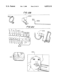
- FIG. 3C illustrates bite-wing blocks 304 a, b, c of the present invention which are employed for X-raying the opposing coronal area, known as the head or crown. As illustrated in FIG. 3C, the bite-wing blocks are provided in different configurations which correspond to different opposing coronal areas.
- FIG. 3D illustrates the anterior arm 306a, the posterior arm 306b and the bitewing arm 306c which couple respective aiming rings to the bite-blocks.
- the indicator arms are constructed to obtain, in combination with the respective aiming ring, the optimum position and alignment for positioning the respective bite-block and X-ray film thereon in the particular dental area to be X-rayed.
- the posterior arm is configured such that, in combination with the posterior aiming ring and posterior bite-block, the dentist achieves optimum position and alignment of the posterior X-ray film for X-raying the posterior dental area.
- the anterior arm is configured such that, in combination with the anterior aiming ring and anterior bite-block, the dentist achieves the optimum position and alignment for the anterior X-ray film for X-raying the anterior dental area.
- the bite-wing arm is configured such that the dentist achieves the optimum position and alignment for X-raying the opposing coronal area.
- the present invention provides quick and easy assembly of the aiming rings, bite-blocks and indicator arms by color coding at least one of these components.
- the aiming rings and bite-blocks are color coded.
- the anterior aiming ring and the anterior bite-block are color coded green whereas the posterior aiming ring and the posterior bite-block are color coded orange.
- the dentist or dental technician it is relatively simple for the dentist or dental technician to identify by the color coding scheme of the present invention the correct aiming ring and corresponding bite-block.
- other colors may be chosen for representing the components of the positioner of the present invention.
- the indicator arms are not color coded.
- the indicator arms as well may be color coded.
- the posterior arm in the foregoing example may be color coded orange while the anterior arm may be color coded green.
- the bite-wing blocks are also color coded.
- the bite-wing blocks are color coded white.
- the bite-wing blocks may be color coded to any color. With this arrangement, the dentist or dental technician will not confuse the bite-wing blocks with the bite-blocks.
- the color coding scheme of the present invention provides the dentist or dental technician with the capability to quickly and easily assemble all the interchangeable parts of the positioner according to the color coding thereby resulting in the optimum position and alignment for X-raying the particular dental area.
- the dentist quickly and easily assembles the color coded anterior bite-block, the anterior arm and the anterior aiming ring according to the color coding scheme which matches the colors of one or more components in the anterior positioner.
- FIG. 2B illustrates that the posterior positioner is assembled quickly and easily by color coding one or more of the posterior aiming ring, the posterior bite-block and the posterior arm.
- the present invention in particular, is effective for providing the optimum position and alignment for dental-X-raying the following regions: Maxillary Incisor, Maxillary Lateral Incisor, Maxillary Cuspid, Maxillary Bicuspid (Premolar), Maxillary Molar, Mandibular Incisor, Mandibular Cuspid, Mandibular Bicuspid (Premolar), Mandibular Molar, Interproximial Bicuspid (Premolar) and Interproximial Molar.
- regions of the mouth are certainly within the scope of the present invention.
- FIGS. 4A-C A method for employing the color coding scheme of the present invention will now be described for each of the aforementioned regions.
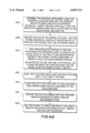
- the operator For X-raying the maxillary incisor region, reference to FIGS. 4A-C is made.
- the operator assembles the anterior positioner using the anterior localizing ring 402 and the anterior indicator arm 406 along with the anterior bite-block 404.
- the film is inserted vertically into the bite-block with the all-white side of the film facing the X-ray PID.
- FIG. 4B shows that the anterior localizing ring and the anterior bite-block are color coded, it will be appreciated that one or more of the components shown in FIG. 4B may be color coded.
- step 400B the operator centers the film on the central incisors 408 as shown in FIG. 4C. It is preferred that the entire horizontal length of the bite-block is used to position the film well into the posterior aspect 410 as shown in FIG. 4C.
- step 400C with the bite-block portion of the film positioner (the horizontal part) placed on the incisal edge of the teeth to be radial graphed, the operator instructs the patient to bite down firmly 412 in order to hold the film in proper position.
- a cotton roll or "cushie" between the film positioner and the incisal edge for added patient comfort may be provided.
- the operator in step 400D slides the localizing ring along the indicator arm until it is close to the skin of the patient.
- step 400E the operator aligns the PID of the X-ray unit to the localizing ring, making sure that the PID is centered to the localizing ring.
- the operator in step 400F, exposes the film, following the X-ray and/or film manufacturer's impulse recommendations.
- step 400G the operator asks the patient to open their mouth, and gently removes the entire positioning device. The X-ray film is removed for processing. Examples of the developed X-ray film is indicated by the negatives 414 shown in FIG. 4C.
- FIGS. 5A-C illustrate the method of X-raying the maxillary lateral incisor region according to the present invention.
- steps 500A-G are similar to those shown in FIG. 4A except that the operator positions the positioner of the present invention to X-ray the maxillary lateral incisor region 510 shown in FIG. 5C.
- the operator assembles the anterior localizing ring 502, the anterior bite-block 504 and the anterior arm 506 shown in FIG. 5B.
- the size of the X-ray film used is of size 1 (anterior size), however, the X-ray film may, of course, vary according to the needs of the operator.
- the operator positions the X-ray film proximate to the maxillary lateral incisor region 508 as shown in FIG. SC by adjusting, for example as shown by reference numeral 512, resulting in the exemplary negatives 514 shown in FIG. 5C.
- step 600A the operator assembles the anterior positioner of the present invention using the anterior localizing ring 602 and the anterior indicating arm 606 along with an anterior bite-block 604. The operator, then, inserts the film vertically into the bite-block, making sure the all-white side of the film is facing the X-ray PID.
- a size 1 (anterior size) film is required but, of course, other size films such as a size 2 (adult size periapical) film may be used.
- the film may require shaping, such as curling the anterior comer slightly to aid in the positioning of the instrument.
- step 600B the operator positions the film with the cuspid and the first bicuspid centered on the film. It is preferred that the entire horizontal length of the bite-block is used to position the film well into the posterior aspect.
- Steps 600C-G are similar to the previously described steps of FIG. 4A and a description thereof is referred thereto.
- the dentist assembles the anterior localizing ring 602, the anterior bite-block 604 and the anterior arm 606 as shown in FIG. 6B and positions the film proximate to the maxillary cuspid region 608, 610 and 612 which results in the exemplary negatives 614 shown in FIG. 6C.
- FIGS. 7A-C illustrate the method for X-raying the maxillary bicuspid (premolar) region 708 shown in FIG. 7C.
- the operator assembles the posterior positioner of the present invention using the posterior localizing ring 702, the posterior indicator arm 706 and the posterior bite-block 704 shown in FIG. 7B.
- the operator inserts the film vertically into the bite-block, making sure that the all-white side of the film is facing the X-ray PID. It may be necessary to curl the upper anterior comer slightly to aid in positioning the instrument.
- step 700B the film is centered on the second bicuspid, for example, using the entire horizontal length of the bite-block to position the film well in the mid-palatial aspect 710 as shown in FIG. 7C.
- Steps 700C-G are similar to steps 400C-G and a description is found in the corresponding sections of the specification.
- the operator positions the positioner of the present invention as shown in reference numeral 712 in FIG. 7C resulting in the developed X-ray negative example 714 shown in FIG. 7C.
- FIGS. 8A-C The method for X-raying the maxillary molar region is illustrated in FIGS. 8A-C.
- the operator in step 800A assembles the posterior positioner of the present invention using the posterior localizing ring 802, the posterior indicator arm 806 and the posterior bite-block 804.
- the film is inserted horizontally into the bite-block making sure that the all-white side of the film is facing the X-ray PID. It may be necessary to curl the upper anterior comer slightly to aid in the positioning of the instrument.
- step 800B the film is centered on a second molar 808 as shown in FIG. 8C using the entire horizontal length of the bite-block to position the film in the mid-palatal aspect 810.
- Steps 800C-G are similar t6 400C-G and the description thereof is referred to the corresponding sections of the specification.
- the operator positions the position of the present invention as shown in 812 resulting in the X-ray negative example 814 shown in FIG. 8C.
- FIGS. 9A-C The method for X-raying the mandibular incisor region 908 is illustrated in FIGS. 9A-C.
- the operator assembles the anterior positioner of the present invention using the anterior localizing ring 902 and the anterior indicator arm 906 with an anterior bite-block 904.
- the film (number 1 or 2 size) is inserted vertically into the bite-block with the all-white side of the film facing the X-ray PID. It may be necessary to curl the upper anterior comer slightly to aid in positioning the instrument of the present invention.
- step 900B the operator centers the film along the central incisors 908.
- Lingual placement of the film packet is preferably made as well into the posterior as allowable by the anatomy of the patient as shown in 910 of FIG. 9C.
- the bite-block of the film positioner horizontal part
- the patient With the bite-block of the film positioner (horizontal part) placed on the incisal edge of the teeth to be radial graphed, the patient is instructed to bite down firmly 912 in order to hold the film in proper position.
- Steps 900D-G are similar to 400D-G and the description thereof is referred to the corresponding sections of the specification.
- the exemplary X-ray negatives 914 of the mandibular incisor region are produced.
- FIGS. 10A-C The method for X-raying the mandibular cuspid region 1008 is illustrated in FIGS. 10A-C.
- step 1000A the operator assembles the anterior positioner of the present invention using the anterior localizing ring 1002 and the anterior indicator arm 1006 with the anterior bite-block 1004.
- the film is inserted vertically into the bite-block with the all-white side of the film facing the X-ray PID. It may be necessary to curl the upper anterior comer slightly to aid in the positioning of the instrument of the present invention.
- step 1000B the film is centered on the cuspid and first bicuspid 1008 as shown in 1010 of FIG. 3C.
- step 1000C With the bite-block of the film positioner (the horizontal portion) placed on the mandibular surface of the teeth to be radial graphed, the patient is instructed to bite down firmly 1012 in order to hold the film in proper position. Since steps 1000D-G are similar to 400D-G, a description thereof is referred to the corresponding sections of the specification. With the method of the present invention, the exemplary X-ray negatives 1014 shown in FIG. 10C are developed.
- step 1200A the operator assembles the posterior positioner of the present invention using the posterior localizing ring 1102, the posterior indicator arm 1106 and the posterior bite-block 1104.
- the film is inserted into the bite-block with the all-white side of the film facing the X-ray PID. It may be necessary to curl the lower anterior comer slightly to aid in the positioning of the instrument.
- step 1100C with the bite-block portion of the film positioner (the horizontal portion) placed on the occlusal surface of the teeth to be radial graphed, the patient is instructed to bite down firmly in order to hold the film in proper position as shown in 1112 of FIG. 11C.
- Steps 1100D-G are similar to 400D-G and a detailed description thereof is referred to the corresponding section of the specification.
- the exemplary X-ray negative 1114 shown in FIG. 11C is developed.
- step 1200A the operator assembles the posterior positioner of the present invention using the posterior localizing ring 1202 and the posterior indicator arm 1206 along with the posterior bite-block 1204.
- the film is inserted into the bite-block with the all-white side of the film facing the X-ray PID. It may be necessary to curl the lower interior comer slightly to aid in positioning the instrument.
- step 1200B the film is centered on the second molar 1208. Lingual placement of the film should be made as medial as the tongue of the patient will allow.
- step 1200C the bite-block portion of the film positioner (the horizontal portion) is placed on the occlusal surface of the teeth to be radial graphed as shown by 1210 and the patient is instructed to bite-down firmly in order to hold the film in proper position as shown in 1212 of FIG. 12C.
- the steps 1200D-G are similar to steps 400D-G of FIG. 4A and a description thereof is referred to the corresponding sections of the specification.
- the exemplary X-ray negative 1214 is developed.
- step 1300A the operator assembles the bite-wing positioner of the present invention using the bite-wing localizing ring 1302, the bite-wing indicator arm 1306 and the interproximal bite-block 1304.
- the horizontal side of the film packet is inserted onto one side of the bite-block.
- the film is inserted into the opposite side into the other side of the bite-block making sure that the all-white side of the film is facing the X-ray PID.
- the operator centers the film in step 1300B.
- step 1300C the bite-block lying on the occlusal surface of the mandibular teeth, align the interior edge of the film as shown in 1310 of FIG. 13C with the distal portion of the mandibular cuspid. It is preferred that the bite-block rests on the opposite side of the arch to the teeth being radial graphed.
- step 1300D the patient is instructed to bite-down firmly and check to insure that the correct film position has been maintained ass shown by 1312 of FIG. 13C.
- step 1300E the operator slides the localizing ring along the indicator arm until it is close to the skin.
- the PID of the X-ray unit is aligned to the localizing ring, making sure that the PID is centered to the localizing ring.
- the film is exposed following the X-ray machine and/or film manufacturer's impulse recommendations.
- the patient is asked to open their mouth and gently remove the entire positioning device and the film is removed for processing.
- the exemplary X-ray negative 1314 is developed.
- step 1400A the operator assembles the bite-wing positioner instrument using the bite-wing localizing ring 1402, the bite-wing indicator arm 1406 and the interproximal bite-block 1404. The operator inserts the horizontal side of the film packet into one side of the bite-block. Then, flexing the film, the operator inserts the opposite side into the other side of the bite-block making sure that the all-white side of the film is facing the X-ray PID. In step 1400D, the operator centers the film.
- step 1400C with the bite-block lying on the occlusal surface of the mandibular teeth, the anterior edge of the film is aligned with the distal portion of the second bicuspid. It is preferred that the bite-block rests on the opposite side of the arch to the teeth being radial graphed as shown in 1410 of FIG. 14C.
- step 1400D the patient is instructed to bite down firmly and check to insure that the correct film position has been maintained in 1412 of FIG. 14C.
- the steps 1400E-H are similar to steps 1300E-H and a description thereof is referred to the corresponding sections of the specification. With the present invention, the exemplary X-ray negative 1414 is developed.
- the present invention provides a rapid system, method and apparatus for assembling a positioner for performing a dental X-ray by providing color coded parts for easy assembly.
- the foregoing description is directed to use of the anterior, posterior and bite-wing exams, it will be appreciated that the present invention is not limited thereby but may be applicable to X-ray exams of any kind including medical X-rays. It will further be appreciated that the present invention provides a cost-effective solution to the problem of interchangeable positioner components while maintaining the interchangeability of the components thereof.
Landscapes
- Health & Medical Sciences (AREA)
- Life Sciences & Earth Sciences (AREA)
- Engineering & Computer Science (AREA)
- Medical Informatics (AREA)
- General Health & Medical Sciences (AREA)
- Physics & Mathematics (AREA)
- Nuclear Medicine, Radiotherapy & Molecular Imaging (AREA)
- Heart & Thoracic Surgery (AREA)
- High Energy & Nuclear Physics (AREA)
- Veterinary Medicine (AREA)
- Oral & Maxillofacial Surgery (AREA)
- Optics & Photonics (AREA)
- Pathology (AREA)
- Radiology & Medical Imaging (AREA)
- Biomedical Technology (AREA)
- Biophysics (AREA)
- Molecular Biology (AREA)
- Surgery (AREA)
- Animal Behavior & Ethology (AREA)
- Public Health (AREA)
- General Physics & Mathematics (AREA)
- Dentistry (AREA)
- Apparatus For Radiation Diagnosis (AREA)
Abstract
Color coding the components of a dental positioner, including an aiming ring, a bite block and an indicator arm allows the operator to assemble the correct positioner for proper positioning and alignment according to a particular dental area to be X-rayed. The color coding corresponds to different dental areas including the anterior and posterior dental areas. For coronal areas, a bite-wing block is provided which also may be in the color coded.
Description
1. Field of the Invention
The present invention relates to a color coding method and apparatus and, more particularly, a color coding method and apparatus for an X-ray positioning system.
2. Description of the Related Art
The dental X-ray is vital to the diagnosis and treatment of the patient's teeth. The dental X-ray provides the dentist with a quick and accurate picture of the patient's teeth with which the dentist initially diagnoses a new patient's teeth and determines the course of treatment which may include root canals, cavity feelings, wisdom teeth extractions, etc. Since the dental X-ray provides the dentist with an interior picture of the teeth, the dentist can determine almost immediately what the condition of the teeth is and what course of action to take in the treatment of the teeth. The dental X-ray is so fundamental to the dentist's practice that it is the first thing the dentist requires when treating a new patient.
Dental X-raying techniques have evolved over the years. The most primitive dental X-ray technique involved the dentist placing a small X-ray film within the patient's mouth and exposing the X-ray film to X-rays from an X-ray machine emitter which was placed proximate to the patient's face such that the X-ray is directed to the X-ray film.
It was determined that the best quality X-ray images were obtained by the so-called "paralleling technique" whose basic principle for intraoral periapical films is that the film and the long axis of the tooth being radial graphed is parallel to each other, and the central ray of the X-ray beam is directed perpendicular to both. To accomplish this parallelism, it was determined that the object, i.e. tooth, to film distance must be increased.
Problematically, this object-to-film distance was sizeable in some areas, such as the maxillary molar position where the X-ray film was held in the midline of the palate of the mouth, to achieve this parallelism. This made holding the X-ray film in the patient's mouth difficult while the X-ray film was exposed. Another problem is that the increased object-to-film distance resulted in a loss of image definition, or sharpness.
In order to compensate for this loss of definition due to the sizeable object-to-film distance, it was found that a 16 inch focal film distance was necessary. To implement the 16 inch focal film distance, a long cone was attached to the X-ray emitter which functioned to provide this distance. Unfortunately, the "long cone technique" as it has become to be known, emphasizes the length of the PID rather than the parallel relationship of the object and the film.
In order to assist the dentist in positioning the film parallel to the teeth with such a long cone, positioners were developed which couple the cone to the film such that the cone and film are in alignment. As shown in FIG. 1, for example, the positioner comprises an aiming ring 100 which attaches to the cone 102, an indicator arm 104 which is held by the aiming ring and a bite-block 106 which holds the X-ray film. With this arrangement, the dentist need only position the film parallel to the teeth and the film, teeth and cone are in alignment such that the film and the teeth are parallel and the cone of the X-ray beam is perpendicular to both.
However, positioners do not take into account the different areas of the patient's mouth, known as the four quadrants. Problematically, each of the four quadrants of the patient's mouth requires different types of X-ray films, has different bites and is in different positions of the patient's mouth. Thus, there are different X-ray films for X-raying different teeth, different bite-blocks to receive different bites from the patient's mouth and different indicator arms for positioning the X-ray film in the proper position in the areas of the patient's mouth. In addition, the aiming ring needed to be modified for different positions in order to properly direct the indicator arm to the desired area of the patient's mouth.
This led to the dental practice of interchanging the X-ray films, the bite-blocks, the indicator arms and the aiming rings to achieve parallelism when X-raying different teeth in the patient's mouth. Problematically, the many interchangeable X-ray films, bite-blocks, indicator arms and aiming rings were confusing which resulted in the dentist needlessly wasting time determining the correct "set-up" for the desired teeth to be X-rayed. In practice, the dentist found that the proper combination of interchangeable parts could be found only through trial and error leading to further wasted time and discomfort of the patient. In addition, dental assistants likewise found the interchangeable parts confusing and often required the assistance of the dentist which detracted the dentist from other duties such as attending to other patients in the dental office. Since the patient's bill is based on the amount of time the dentist and dental technicians spend with the patient, the unnecessarily wasted time determining the correct combination of interchangeable parts for performing the dental X-ray was reflected in the patients bill.
Heretofore, there has been no system by which the dentist or dental technician quickly and easily determines the correct combination of X-ray film, bite-block, indicator arm and aiming ring for a particular dental area to be X-rayed.
It is an object of the present invention to provide a quick and easy method and apparatus for determining the correct combination of components for performing a dental X-ray on a particular dental area.
The present invention provides a color coding method and apparatus for an X-ray positioning system. In one particular aspect thereof, one or more components of the positioning system including a positioning or aiming ring, an indicator arm and bite-block or bite-wing block such that the dentist or dental assistant quickly identifies the correct components for assembling a particular positioner for X-raying a particular dental area.
FIG. 1 illustrates the conventional positioner;
FIGS. 2A and 2B illustrate the color coding method and apparatus of the present invention;
FIGS. 3A-3D illustrate anterior and posterior components of the present invention;
FIGS. 4A-4C illustrate the method for X-raying the maxillary incisor region;
FIGS. 5A-5C illustrate the method for X-raying the maxillary lateral incisor region;
FIGS. 6A-6C illustrate the method for X-raying the maxillary cuspid region;
FIGS. 7A-7C illustrate the method for X-raying the maxillar bicuspid (premolar) region;
FIGS. 8A-8C illustrate the method for X-raying the maxillar molar region;
FIGS. 9A-9C illustrate the method for X-raying the mandibular incisor region;
FIGS. 10A-10C illustrate the method for X-raying the mandibular cuspid region;
FIGS. 11A-11C illustrate the method for X-raying the mandibular bicuspid (premolar) region;
FIGS. 12A-12C illustrate the method for X-raying the mandibular molar region;
FIGS. 13A-13C illustrate the method for X-raying the interproximal bicuspid (premolar) region; and
FIGS. 14A-14C illustrate the method for X-raying the interproximal molar region.
FIGS. 2A and 2B illustrate two examples of the color coding method and apparatus of the present invention for color coding the components of the dental X-ray. More specifically, FIG. 2A illustrates an interior positioning system wherein the components thereof are color coded for X-raying interior dental areas. In FIG. 2B, a posterior positioner is illustrated with components color coded for X-raying posterior dental areas of the patient. It will be appreciated that the colors chosen may be any combination of colors.
FIG. 3A illustrates the anterior and posterior aiming rings. As will be appreciated, the anterior aiming ring is constructed with a holding member 300a for holding an anterior arm such that the anterior bite-block and X-ray film thereon are directed to the optimum position and alignment for X-raying the anterior dental area of the patient's teeth. In the figure illustrated, the holding member 300a of the anterior aiming ring is directed away from the longitudinal axis of the anterior aiming ring and is extended in the approximate direction of the X-ray beam. The posterior aiming ring by contrast, includes a holding member 300b which is constructed for holding a posterior arm at the optimum position such that the posterior bite-block and X-ray film thereon are placed at the optimum position and alignment for X-raying posterior areas of the patient's teeth. As illustrated in FIG. 3B, the holding member 300b is closer to the longitudinal axis of the posterior aiming ring and is truncated in the direction of the X-ray beam as compared with the anterior aiming ring. It will be appreciated that the particular arrangements of the anterior and posterior aiming rings may vary according to the desired dental area to be X-rayed.
FIG. 3B illustrates the anterior bite-block 302a for holding anterior X-ray films at the anterior of the dental area of the patient's mouth and the posterior bite-block 302b for holding posterior X-ray films at the posterior of the patient's mouth. As illustrated in FIG. 3B, the anterior bite-block is constructed in a more narrow and elongated arrangement which is optimum for X-raying anterior dental areas of the patient's teeth. By contrast, the posterior bite-block is constructed wider and more stout which is optimum for X-raying posterior dental areas of the patient's teeth.
FIG. 3C illustrates bite-wing blocks 304 a, b, c of the present invention which are employed for X-raying the opposing coronal area, known as the head or crown. As illustrated in FIG. 3C, the bite-wing blocks are provided in different configurations which correspond to different opposing coronal areas.
FIG. 3D illustrates the anterior arm 306a, the posterior arm 306b and the bitewing arm 306c which couple respective aiming rings to the bite-blocks. As illustrated in FIG. 3D, the indicator arms are constructed to obtain, in combination with the respective aiming ring, the optimum position and alignment for positioning the respective bite-block and X-ray film thereon in the particular dental area to be X-rayed. In particular, the posterior arm is configured such that, in combination with the posterior aiming ring and posterior bite-block, the dentist achieves optimum position and alignment of the posterior X-ray film for X-raying the posterior dental area. Similarly, the anterior arm is configured such that, in combination with the anterior aiming ring and anterior bite-block, the dentist achieves the optimum position and alignment for the anterior X-ray film for X-raying the anterior dental area. The bite-wing arm is configured such that the dentist achieves the optimum position and alignment for X-raying the opposing coronal area.
The present invention provides quick and easy assembly of the aiming rings, bite-blocks and indicator arms by color coding at least one of these components. In the preferred embodiment, the aiming rings and bite-blocks are color coded. For example, the anterior aiming ring and the anterior bite-block are color coded green whereas the posterior aiming ring and the posterior bite-block are color coded orange. With this arrangement, it is relatively simple for the dentist or dental technician to identify by the color coding scheme of the present invention the correct aiming ring and corresponding bite-block. Of course, it will be appreciated that other colors may be chosen for representing the components of the positioner of the present invention.
In the embodiment illustrated in the figures, the indicator arms are not color coded. However, it will be appreciated that the indicator arms as well may be color coded. For example, the posterior arm in the foregoing example may be color coded orange while the anterior arm may be color coded green.
In another embodiment, the bite-wing blocks are also color coded. For example, and as shown in the Figures, the bite-wing blocks are color coded white. Of course, the bite-wing blocks may be color coded to any color. With this arrangement, the dentist or dental technician will not confuse the bite-wing blocks with the bite-blocks.
In operation, the color coding scheme of the present invention provides the dentist or dental technician with the capability to quickly and easily assemble all the interchangeable parts of the positioner according to the color coding thereby resulting in the optimum position and alignment for X-raying the particular dental area. As shown in FIG. 2A, for example, the dentist quickly and easily assembles the color coded anterior bite-block, the anterior arm and the anterior aiming ring according to the color coding scheme which matches the colors of one or more components in the anterior positioner. FIG. 2B, for example, illustrates that the posterior positioner is assembled quickly and easily by color coding one or more of the posterior aiming ring, the posterior bite-block and the posterior arm. The present invention, in particular, is effective for providing the optimum position and alignment for dental-X-raying the following regions: Maxillary Incisor, Maxillary Lateral Incisor, Maxillary Cuspid, Maxillary Bicuspid (Premolar), Maxillary Molar, Mandibular Incisor, Mandibular Cuspid, Mandibular Bicuspid (Premolar), Mandibular Molar, Interproximial Bicuspid (Premolar) and Interproximial Molar. Although, other regions of the mouth are certainly within the scope of the present invention.
A method for employing the color coding scheme of the present invention will now be described for each of the aforementioned regions. For X-raying the maxillary incisor region, reference to FIGS. 4A-C is made. As illustrated by the flowchart of FIG. 4A, the operator assembles the anterior positioner using the anterior localizing ring 402 and the anterior indicator arm 406 along with the anterior bite-block 404. The film is inserted vertically into the bite-block with the all-white side of the film facing the X-ray PID. Although FIG. 4B shows that the anterior localizing ring and the anterior bite-block are color coded, it will be appreciated that one or more of the components shown in FIG. 4B may be color coded. In step 400B, the operator centers the film on the central incisors 408 as shown in FIG. 4C. It is preferred that the entire horizontal length of the bite-block is used to position the film well into the posterior aspect 410 as shown in FIG. 4C. In step 400C, with the bite-block portion of the film positioner (the horizontal part) placed on the incisal edge of the teeth to be radial graphed, the operator instructs the patient to bite down firmly 412 in order to hold the film in proper position. In the alternative, a cotton roll or "cushie" between the film positioner and the incisal edge for added patient comfort may be provided. The operator in step 400D slides the localizing ring along the indicator arm until it is close to the skin of the patient. In step 400E, the operator aligns the PID of the X-ray unit to the localizing ring, making sure that the PID is centered to the localizing ring. The operator, in step 400F, exposes the film, following the X-ray and/or film manufacturer's impulse recommendations. In step 400G, the operator asks the patient to open their mouth, and gently removes the entire positioning device. The X-ray film is removed for processing. Examples of the developed X-ray film is indicated by the negatives 414 shown in FIG. 4C.
FIGS. 5A-C illustrate the method of X-raying the maxillary lateral incisor region according to the present invention. In this case, steps 500A-G are similar to those shown in FIG. 4A except that the operator positions the positioner of the present invention to X-ray the maxillary lateral incisor region 510 shown in FIG. 5C. In summary, the operator assembles the anterior localizing ring 502, the anterior bite-block 504 and the anterior arm 506 shown in FIG. 5B. It is preferable that the size of the X-ray film used is of size 1 (anterior size), however, the X-ray film may, of course, vary according to the needs of the operator. The operator, thus, positions the X-ray film proximate to the maxillary lateral incisor region 508 as shown in FIG. SC by adjusting, for example as shown by reference numeral 512, resulting in the exemplary negatives 514 shown in FIG. 5C.
The method for X-raying the maxillary cuspid region is illustrated in FIGS. 6A-C. In step 600A, the operator assembles the anterior positioner of the present invention using the anterior localizing ring 602 and the anterior indicating arm 606 along with an anterior bite-block 604. The operator, then, inserts the film vertically into the bite-block, making sure the all-white side of the film is facing the X-ray PID. Typically, a size 1 (anterior size) film is required but, of course, other size films such as a size 2 (adult size periapical) film may be used. The film may require shaping, such as curling the anterior comer slightly to aid in the positioning of the instrument. In step 600B, the operator positions the film with the cuspid and the first bicuspid centered on the film. It is preferred that the entire horizontal length of the bite-block is used to position the film well into the posterior aspect. Steps 600C-G are similar to the previously described steps of FIG. 4A and a description thereof is referred thereto. In this case, the dentist assembles the anterior localizing ring 602, the anterior bite-block 604 and the anterior arm 606 as shown in FIG. 6B and positions the film proximate to the maxillary cuspid region 608, 610 and 612 which results in the exemplary negatives 614 shown in FIG. 6C.
FIGS. 7A-C illustrate the method for X-raying the maxillary bicuspid (premolar) region 708 shown in FIG. 7C. As shown in FIG. 7A, the operator assembles the posterior positioner of the present invention using the posterior localizing ring 702, the posterior indicator arm 706 and the posterior bite-block 704 shown in FIG. 7B. The operator inserts the film vertically into the bite-block, making sure that the all-white side of the film is facing the X-ray PID. It may be necessary to curl the upper anterior comer slightly to aid in positioning the instrument. In step 700B, the film is centered on the second bicuspid, for example, using the entire horizontal length of the bite-block to position the film well in the mid-palatial aspect 710 as shown in FIG. 7C. Steps 700C-G are similar to steps 400C-G and a description is found in the corresponding sections of the specification. With this method, the operator positions the positioner of the present invention as shown in reference numeral 712 in FIG. 7C resulting in the developed X-ray negative example 714 shown in FIG. 7C.
The method for X-raying the maxillary molar region is illustrated in FIGS. 8A-C. In FIG. 8A, the operator in step 800A assembles the posterior positioner of the present invention using the posterior localizing ring 802, the posterior indicator arm 806 and the posterior bite-block 804. The film is inserted horizontally into the bite-block making sure that the all-white side of the film is facing the X-ray PID. It may be necessary to curl the upper anterior comer slightly to aid in the positioning of the instrument. In step 800B, the film is centered on a second molar 808 as shown in FIG. 8C using the entire horizontal length of the bite-block to position the film in the mid-palatal aspect 810. Steps 800C-G are similar t6 400C-G and the description thereof is referred to the corresponding sections of the specification. With this method, the operator positions the position of the present invention as shown in 812 resulting in the X-ray negative example 814 shown in FIG. 8C.
The method for X-raying the mandibular incisor region 908 is illustrated in FIGS. 9A-C. As shown in FIG. 9A, in step 900A, the operator assembles the anterior positioner of the present invention using the anterior localizing ring 902 and the anterior indicator arm 906 with an anterior bite-block 904. The film (number 1 or 2 size) is inserted vertically into the bite-block with the all-white side of the film facing the X-ray PID. It may be necessary to curl the upper anterior comer slightly to aid in positioning the instrument of the present invention. In step 900B, the operator centers the film along the central incisors 908. Lingual placement of the film packet is preferably made as well into the posterior as allowable by the anatomy of the patient as shown in 910 of FIG. 9C. With the bite-block of the film positioner (horizontal part) placed on the incisal edge of the teeth to be radial graphed, the patient is instructed to bite down firmly 912 in order to hold the film in proper position. Steps 900D-G are similar to 400D-G and the description thereof is referred to the corresponding sections of the specification. With this X-raying method of the present invention, the exemplary X-ray negatives 914 of the mandibular incisor region are produced.
The method for X-raying the mandibular cuspid region 1008 is illustrated in FIGS. 10A-C. In FIG. 10A, in step 1000A the operator assembles the anterior positioner of the present invention using the anterior localizing ring 1002 and the anterior indicator arm 1006 with the anterior bite-block 1004. The film is inserted vertically into the bite-block with the all-white side of the film facing the X-ray PID. It may be necessary to curl the upper anterior comer slightly to aid in the positioning of the instrument of the present invention. In step 1000B, the film is centered on the cuspid and first bicuspid 1008 as shown in 1010 of FIG. 3C. Lingual placement of the film should be made as well into the posterior as allowable by the patient's anatomy 1010. In step 1000C, with the bite-block of the film positioner (the horizontal portion) placed on the mandibular surface of the teeth to be radial graphed, the patient is instructed to bite down firmly 1012 in order to hold the film in proper position. Since steps 1000D-G are similar to 400D-G, a description thereof is referred to the corresponding sections of the specification. With the method of the present invention, the exemplary X-ray negatives 1014 shown in FIG. 10C are developed.
The method for X-raying the mandibular bicuspid (premolar) region 1108 is illustrated in FIGS. 11A-C. In step 1200A, the operator assembles the posterior positioner of the present invention using the posterior localizing ring 1102, the posterior indicator arm 1106 and the posterior bite-block 1104. The film is inserted into the bite-block with the all-white side of the film facing the X-ray PID. It may be necessary to curl the lower anterior comer slightly to aid in the positioning of the instrument. In step 1100C, with the bite-block portion of the film positioner (the horizontal portion) placed on the occlusal surface of the teeth to be radial graphed, the patient is instructed to bite down firmly in order to hold the film in proper position as shown in 1112 of FIG. 11C. Steps 1100D-G are similar to 400D-G and a detailed description thereof is referred to the corresponding section of the specification. With the X-ray method of the present invention, the exemplary X-ray negative 1114 shown in FIG. 11C is developed.
The method for X-raying the mandibular molar region 1208 of the present invention is illustrated in FIGS. 12A-C. In step 1200A, the operator assembles the posterior positioner of the present invention using the posterior localizing ring 1202 and the posterior indicator arm 1206 along with the posterior bite-block 1204. The film is inserted into the bite-block with the all-white side of the film facing the X-ray PID. It may be necessary to curl the lower interior comer slightly to aid in positioning the instrument. In step 1200B, the film is centered on the second molar 1208. Lingual placement of the film should be made as medial as the tongue of the patient will allow. In step 1200C, the bite-block portion of the film positioner (the horizontal portion) is placed on the occlusal surface of the teeth to be radial graphed as shown by 1210 and the patient is instructed to bite-down firmly in order to hold the film in proper position as shown in 1212 of FIG. 12C. The steps 1200D-G are similar to steps 400D-G of FIG. 4A and a description thereof is referred to the corresponding sections of the specification. With the method of the present invention, the exemplary X-ray negative 1214 is developed.
The method for X-raying the interproximal bicuspid (premolar) region 1308 is illustrated in FIGS. 13A-C. In step 1300A, the operator assembles the bite-wing positioner of the present invention using the bite-wing localizing ring 1302, the bite-wing indicator arm 1306 and the interproximal bite-block 1304. The horizontal side of the film packet is inserted onto one side of the bite-block. Then, by flexing the film, the film is inserted into the opposite side into the other side of the bite-block making sure that the all-white side of the film is facing the X-ray PID. The operator centers the film in step 1300B. In step 1300C, the bite-block lying on the occlusal surface of the mandibular teeth, align the interior edge of the film as shown in 1310 of FIG. 13C with the distal portion of the mandibular cuspid. It is preferred that the bite-block rests on the opposite side of the arch to the teeth being radial graphed. In step 1300D, the patient is instructed to bite-down firmly and check to insure that the correct film position has been maintained ass shown by 1312 of FIG. 13C. In step 1300E, the operator slides the localizing ring along the indicator arm until it is close to the skin. In 1300F, the PID of the X-ray unit is aligned to the localizing ring, making sure that the PID is centered to the localizing ring. In step 1300G, the film is exposed following the X-ray machine and/or film manufacturer's impulse recommendations. In step 1300H, the patient is asked to open their mouth and gently remove the entire positioning device and the film is removed for processing. With the method of the present invention, the exemplary X-ray negative 1314 is developed.
The method of X-raying the interproximal molar region 1408 is illustrated in FIGS. 14A-B. In step 1400A, the operator assembles the bite-wing positioner instrument using the bite-wing localizing ring 1402, the bite-wing indicator arm 1406 and the interproximal bite-block 1404. The operator inserts the horizontal side of the film packet into one side of the bite-block. Then, flexing the film, the operator inserts the opposite side into the other side of the bite-block making sure that the all-white side of the film is facing the X-ray PID. In step 1400D, the operator centers the film. In step 1400C, with the bite-block lying on the occlusal surface of the mandibular teeth, the anterior edge of the film is aligned with the distal portion of the second bicuspid. It is preferred that the bite-block rests on the opposite side of the arch to the teeth being radial graphed as shown in 1410 of FIG. 14C. In step 1400D, the patient is instructed to bite down firmly and check to insure that the correct film position has been maintained in 1412 of FIG. 14C. The steps 1400E-H are similar to steps 1300E-H and a description thereof is referred to the corresponding sections of the specification. With the present invention, the exemplary X-ray negative 1414 is developed.
It will be appreciated from the foregoing that the present invention provides a rapid system, method and apparatus for assembling a positioner for performing a dental X-ray by providing color coded parts for easy assembly. Although the foregoing description is directed to use of the anterior, posterior and bite-wing exams, it will be appreciated that the present invention is not limited thereby but may be applicable to X-ray exams of any kind including medical X-rays. It will further be appreciated that the present invention provides a cost-effective solution to the problem of interchangeable positioner components while maintaining the interchangeability of the components thereof.
Although preferred embodiments of the present invention and modifications thereof have been described in detail herein, it is to be understood that this invention is not limited to those precise embodiments and modifications, and that other modifications and variations may be effected by one skilled in the art without departing from the spirit and scope of the invention as defined by the appended claims.
Claims (26)
1. A color coding system for color coding a dental positioner having components when combined according to said color coding form said dental positioner which guides an x-ray for x-raying a particular dental area, said system comprising:
a plurality of components constituting said dental positioner which when combined form said dental positioner which guides said x-ray for x-raying said particular dental area; and
a color-coding for color coding a number of said components for identifying said components as corresponding to said particular dental area to be x-rayed such that, when said components are combined in accordance with said color-coding, said dental positioner formed guides said x-ray for x-raying said particular dental area.
2. The system according to claim 1, wherein said dental positioner when combined according to said color-coding guides said x-ray such that said x-ray is substantially perpendicular to said dental area x-rayed.
3. The system according to claim 1, wherein said dental positioner has at least one color-coded component for holding x-ray film in a mouth and at least one color-coded component for receiving an x-ray cone which transmits said x-ray.
4. The system according to claim 1, wherein said dental area is one of a plurality of types of dental areas; wherein said components are color-coded according to different types of dental areas.
5. The system according to claim 4, wherein the different types of dental areas are distinguished by different bites of a mouth.
6. The system according to claim 4, wherein the different types of dental areas are distinguished by different types of x-ray film to photograph associated different areas.
7. The system according to claim 3, wherein said color-coded component for receiving an x-ray cone is an aiming ring and said color-coded component for holding is a bite block.
8. The system according to claim 7, wherein said aiming ring and said bite block are both color coded to a particular dental area.
9. The system according to claim 7, wherein said components further include an indicator arm for coupling said aiming ring to said bite block.
10. The system according to claim 9, wherein said bite block is a bite-wing block.
11. The system according to claim 7, wherein said color-coding color codes said aiming ring to a bite block according to the anterior and posterior areas of the mouth.
12. A color coding method for color coding components of a dental positioner which when combined according to said color coding form said dental positioner which guides an x-ray for x-raying a particular dental area, said method comprising the steps of:
providing a plurality of components constituting said dental positioner which when combined form said dental positioner which guides said x-ray for x-raying said particular dental area; and
color-coding a number of said components according to said dental area such that, when said components are combined in accordance with said color-coding, said dental positioner formed guides said x-ray for x-raying said dental area.
13. The method according to claim 12 wherein said step of providing provides said components such that when combined in accordance with said color coding form said dental positioner which guides said x-ray substantially perpendicular to said dental area.
14. The method according to claim 13, wherein said step of providing provides a color-coded component for holding x-ray film to image said x-raying and a color-coded component which receives an x-ray cone which transmits said x-ray.
15. The method according to claim 12, wherein said step of color-coding color codes said components according to one of a plurality of types of dental areas.
16. The method according to claim 15, wherein said step of color-coding color codes said components according to a type of dental area distinguished by a type of bite.
17. The method according to claim 15, wherein said step of color-coding color codes said components according to a type of dental area distinguished by type of area of a mouth.
18. The method according to claim 14, wherein said step of providing provides an aiming ring as said color-coded component for receiving said x-ray cone and a bite block as said color-coded component for holding said x-ray film.
19. The method according to claim 18, wherein said step of providing provides an indicator arm for coupling said aiming ring and said bite block.
20. The method according to claim 18, wherein said step of color coding color codes a particular aiming ring to a particular bite block according to anterior and posterior areas of the mouth.
21. The method according to claim 20, wherein the step of providing components provides as a bite block a bite-wing b lock.
22. A method for assembling a dental positioner by combining a number of color-coded components which when combined according to color coding form said dental positioner which guides an x-ray for x-raying a particular dental area, said method comprising the steps of:
determining particular ones of said number of said components which when combined according to said color coding form said dental positioner which guides said x-ray for x-raying said particular dental area; and
assembling said particular ones of said components according to said color-coding to form said dental positioner which guides said x-ray for x-raying said particular dental area.
23. The method according to claim 22, wherein said step of assembling assembles a holding device for holding x-rays with a positioner for receiving an x-ray cone which transmits said x-ray.
24. The method according to claim 22, further comprising the step of inserting the assembled components in a mouth such that an axis of said x-ray is perpendicular to the particular dental area to be x-rayed.
25. The method according to claim 23, wherein said holding device is a bite block and said positioner is an aiming ring.
26. The method according to claim 25, wherein said color-coded components include an indicator arm.
Priority Applications (1)
| Application Number | Priority Date | Filing Date | Title |
|---|---|---|---|
| US09/196,020 US6033111A (en) | 1998-11-20 | 1998-11-20 | Color coding method and apparatus for an X-ray positioning system |
Applications Claiming Priority (1)
| Application Number | Priority Date | Filing Date | Title |
|---|---|---|---|
| US09/196,020 US6033111A (en) | 1998-11-20 | 1998-11-20 | Color coding method and apparatus for an X-ray positioning system |
Publications (1)
| Publication Number | Publication Date |
|---|---|
| US6033111A true US6033111A (en) | 2000-03-07 |
Family
ID=22723805
Family Applications (1)
| Application Number | Title | Priority Date | Filing Date |
|---|---|---|---|
| US09/196,020 Expired - Fee Related US6033111A (en) | 1998-11-20 | 1998-11-20 | Color coding method and apparatus for an X-ray positioning system |
Country Status (1)
| Country | Link |
|---|---|
| US (1) | US6033111A (en) |
Cited By (31)
| Publication number | Priority date | Publication date | Assignee | Title |
|---|---|---|---|---|
| US6190042B1 (en) * | 1998-09-29 | 2001-02-20 | Electro Medical Systems | Dental x-ray aiming device for longitudinal radiographic analysis |
| US6343875B1 (en) | 1999-06-30 | 2002-02-05 | Dentsply Research & Development Corp. | Modular bite block and sensor holder apparatus for dental x-ray procedures |
| US6540399B1 (en) | 1999-02-26 | 2003-04-01 | Dentsply Research & Development Corp. | Bite block for dental X-Ray procedures |
| US20050013412A1 (en) * | 2003-07-17 | 2005-01-20 | Calderwood Mitchell C. | Radiographic sensor positioning system |
| US20050185767A1 (en) * | 2004-02-25 | 2005-08-25 | Puente Carlos G. | X-ray positioning device |
| US20060013365A1 (en) * | 2004-07-16 | 2006-01-19 | Becht Darrell A | Method and apparatus for supporting a dental X-ray sensor |
| US20060098787A1 (en) * | 2004-11-11 | 2006-05-11 | Schmulenson Harold K | Holder for an x-ray sensing device |
| US20060188064A1 (en) * | 2005-02-23 | 2006-08-24 | Razzano Michael R | Image capture device and methods |
| US20070053497A1 (en) * | 2005-08-23 | 2007-03-08 | Schmulenson Harold K | Instrument for holding and aligning an x-ray sensing device |
| US20070092061A1 (en) * | 2005-02-23 | 2007-04-26 | Interactive Diagnostic Imaging, Inc. | Image capture device and methods |
| US20080095321A1 (en) * | 2003-07-17 | 2008-04-24 | Calderwood Mitchell C | Radiographic sensor positioning system |
| WO2008103460A2 (en) * | 2007-02-22 | 2008-08-28 | Dentsply International Inc. | Color coded dental x-ray positioning device |
| US20080298543A1 (en) * | 2005-02-23 | 2008-12-04 | Razzano Michael R | Image capture device and methods |
| US20090136002A1 (en) * | 2007-11-26 | 2009-05-28 | Schmulenson Harold K | Radiation sensing device and holder |
| US20100102241A1 (en) * | 2008-10-27 | 2010-04-29 | Uwe Zeller | System and method of x-ray detection with a sensor |
| US20100166151A1 (en) * | 2008-12-29 | 2010-07-01 | Schmulenson Harold K | Holder for radiation sensing device |
| US20100195790A1 (en) * | 2009-02-04 | 2010-08-05 | Asbel Rodrigues Machado | Radiographic film positioning device and a process for obtaining radiographic images |
| US20110013745A1 (en) * | 2009-07-17 | 2011-01-20 | Imaging Sciences International Llc | Intraoral x-ray sensor with embedded standard computer interface |
| US20110013746A1 (en) * | 2008-10-27 | 2011-01-20 | Imaging Sciences International Llc | Triggering of intraoral x-ray sensor using pixel array sub-sampling |
| US8142074B2 (en) | 2007-11-26 | 2012-03-27 | Schmulenson Harold K | Radiation sensing device and holder |
| US20130089185A1 (en) * | 2011-10-07 | 2013-04-11 | William Winters | Dental x-ray receptor positioning device |
| US20140056415A1 (en) * | 2012-08-22 | 2014-02-27 | Schick Technologies, Inc. | Dental positioning system |
| US20140270068A1 (en) * | 2013-03-15 | 2014-09-18 | Zuma Dental, LLC | Imaging system and method |
| US20150116485A1 (en) * | 2012-07-04 | 2015-04-30 | Hemang Subramanian | Device to shade persons from bright sunshine, dynamically from large height by matching shade pattern to presence |
| US9245161B2 (en) | 2010-05-13 | 2016-01-26 | Carestream Health, Inc. | Method and system for computed radiography using a radio frequency identification device |
| US20170065236A1 (en) * | 2015-08-12 | 2017-03-09 | Densmart Dental Co., Ltd. | Bite-block and film-holding device |
| USD861876S1 (en) * | 2018-01-29 | 2019-10-01 | Flow Dental Products, Llc | Aiming ring |
| USD972142S1 (en) * | 2021-05-05 | 2022-12-06 | Surround Medical Systems, Inc. | Detector holder arm anterior |
| USD972143S1 (en) * | 2021-05-05 | 2022-12-06 | Surround Medical Systems, Inc. | Detector holder arm posterior |
| USD972141S1 (en) * | 2021-05-05 | 2022-12-06 | Surround Medical Systems, Inc. | Detector holder arm bitewing |
| USD972729S1 (en) * | 2021-05-05 | 2022-12-13 | Surround Medical Systems, Inc. | Detector holder coupler ring |
Citations (3)
| Publication number | Priority date | Publication date | Assignee | Title |
|---|---|---|---|---|
| US3962807A (en) * | 1974-12-17 | 1976-06-15 | Chi Systems, Inc. | X-ray film coded identification system |
| US4048506A (en) * | 1975-01-17 | 1977-09-13 | Updegrave William J | Versatile intraoral radiographic film positioning system |
| US5289919A (en) * | 1993-02-16 | 1994-03-01 | Ultradent Products, Inc. | Endodontic dental kit with color-coding means |
-
1998
- 1998-11-20 US US09/196,020 patent/US6033111A/en not_active Expired - Fee Related
Patent Citations (3)
| Publication number | Priority date | Publication date | Assignee | Title |
|---|---|---|---|---|
| US3962807A (en) * | 1974-12-17 | 1976-06-15 | Chi Systems, Inc. | X-ray film coded identification system |
| US4048506A (en) * | 1975-01-17 | 1977-09-13 | Updegrave William J | Versatile intraoral radiographic film positioning system |
| US5289919A (en) * | 1993-02-16 | 1994-03-01 | Ultradent Products, Inc. | Endodontic dental kit with color-coding means |
Cited By (63)
| Publication number | Priority date | Publication date | Assignee | Title |
|---|---|---|---|---|
| US6190042B1 (en) * | 1998-09-29 | 2001-02-20 | Electro Medical Systems | Dental x-ray aiming device for longitudinal radiographic analysis |
| US6540399B1 (en) | 1999-02-26 | 2003-04-01 | Dentsply Research & Development Corp. | Bite block for dental X-Ray procedures |
| US6343875B1 (en) | 1999-06-30 | 2002-02-05 | Dentsply Research & Development Corp. | Modular bite block and sensor holder apparatus for dental x-ray procedures |
| US7097356B2 (en) * | 2003-07-17 | 2006-08-29 | Dentex Limited Partnership | Radiographic sensor positioning system |
| US20050013412A1 (en) * | 2003-07-17 | 2005-01-20 | Calderwood Mitchell C. | Radiographic sensor positioning system |
| US20080095321A1 (en) * | 2003-07-17 | 2008-04-24 | Calderwood Mitchell C | Radiographic sensor positioning system |
| US7290928B2 (en) * | 2003-07-17 | 2007-11-06 | Calderwood Mitchell C | Radiographic sensor positioning system |
| US7661880B2 (en) * | 2003-07-17 | 2010-02-16 | Calderwood Mitchell C | Radiographic sensor positioning system |
| US20060245549A1 (en) * | 2003-07-17 | 2006-11-02 | Calderwood Mitchell C | Radiographic sensor positioning system |
| US20050185767A1 (en) * | 2004-02-25 | 2005-08-25 | Puente Carlos G. | X-ray positioning device |
| US7036985B2 (en) | 2004-02-25 | 2006-05-02 | Ultradent Products, Inc. | X-ray positioning device |
| US7261463B2 (en) * | 2004-07-16 | 2007-08-28 | Becht Darrell A | Method and apparatus for supporting a dental X-ray sensor |
| US20060013365A1 (en) * | 2004-07-16 | 2006-01-19 | Becht Darrell A | Method and apparatus for supporting a dental X-ray sensor |
| US20060098787A1 (en) * | 2004-11-11 | 2006-05-11 | Schmulenson Harold K | Holder for an x-ray sensing device |
| US7607830B2 (en) | 2004-11-11 | 2009-10-27 | Schmulenson Harold K | Holder for an x-ray sensing device |
| US7607831B2 (en) | 2004-11-11 | 2009-10-27 | Schmulenson Harold K | Ring guide adapter |
| US7226208B2 (en) | 2004-11-11 | 2007-06-05 | Schmulenson Harold K | Holder for an x-ray sensing device |
| US20080025468A1 (en) * | 2004-11-11 | 2008-01-31 | Schmulenson Harold K | Holder for an x-ray sensing device |
| US20060188064A1 (en) * | 2005-02-23 | 2006-08-24 | Razzano Michael R | Image capture device and methods |
| US20080298543A1 (en) * | 2005-02-23 | 2008-12-04 | Razzano Michael R | Image capture device and methods |
| US7382860B2 (en) | 2005-02-23 | 2008-06-03 | Interactive Diagnostic Imaging, Inc. | Image capture device and methods |
| US7360948B2 (en) | 2005-02-23 | 2008-04-22 | Interactive Diagnostics Imaging, Inc. | Image capture device and methods |
| US7194064B2 (en) | 2005-02-23 | 2007-03-20 | Interactive Diagnostic Imaging, Inc. | Image capture device and methods |
| US20070092061A1 (en) * | 2005-02-23 | 2007-04-26 | Interactive Diagnostic Imaging, Inc. | Image capture device and methods |
| US20070053497A1 (en) * | 2005-08-23 | 2007-03-08 | Schmulenson Harold K | Instrument for holding and aligning an x-ray sensing device |
| US7425095B2 (en) | 2005-08-23 | 2008-09-16 | Harold K. Schmulenson | Instrument for holding and aligning an x-ray sensing device |
| WO2008103460A3 (en) * | 2007-02-22 | 2008-10-16 | Dentsply Int Inc | Color coded dental x-ray positioning device |
| WO2008103460A2 (en) * | 2007-02-22 | 2008-08-28 | Dentsply International Inc. | Color coded dental x-ray positioning device |
| JP2010518974A (en) * | 2007-02-22 | 2010-06-03 | デンツプライ インターナショナル インコーポレーテッド | Color-coded dental X-ray positioning device |
| US8876375B2 (en) | 2007-02-22 | 2014-11-04 | Dentsply International Inc. | Color coded dental X-ray positioning device |
| US20090136002A1 (en) * | 2007-11-26 | 2009-05-28 | Schmulenson Harold K | Radiation sensing device and holder |
| US8142074B2 (en) | 2007-11-26 | 2012-03-27 | Schmulenson Harold K | Radiation sensing device and holder |
| US9354506B2 (en) | 2007-11-26 | 2016-05-31 | Harold K. Schmulenson | Radiation sensing device and holder |
| US7819579B2 (en) | 2007-11-26 | 2010-10-26 | Schmulenson Harold K | Radiation sensing device and holder |
| US20100102241A1 (en) * | 2008-10-27 | 2010-04-29 | Uwe Zeller | System and method of x-ray detection with a sensor |
| US9510796B2 (en) | 2008-10-27 | 2016-12-06 | Dental Imaging Technologies Corporation | Intraoral x-ray sensor with embedded standard computer interface |
| US20110013746A1 (en) * | 2008-10-27 | 2011-01-20 | Imaging Sciences International Llc | Triggering of intraoral x-ray sensor using pixel array sub-sampling |
| US8119990B2 (en) | 2008-10-27 | 2012-02-21 | Imaging Sciences International Llc | System and method of X-ray detection with a sensor |
| US9259197B2 (en) | 2008-10-27 | 2016-02-16 | Dental Imaging Technologies Corporation | Intraoral x-ray sensor with embedded standard computer interface |
| US8324587B2 (en) | 2008-10-27 | 2012-12-04 | Imaging Sciences International Llc | Method and system of reducing false triggering of an X-ray sensor |
| US9492129B2 (en) | 2008-10-27 | 2016-11-15 | Dental Imaging Technologies Corporation | Triggering of intraoral X-ray sensor using pixel array sub-sampling |
| US8333507B2 (en) | 2008-12-29 | 2012-12-18 | Schmulenson Harold K | Holder for radiation sensing device |
| US20100166151A1 (en) * | 2008-12-29 | 2010-07-01 | Schmulenson Harold K | Holder for radiation sensing device |
| US7866883B2 (en) * | 2009-02-04 | 2011-01-11 | Asbel Rodrigues Machado | Radiographic film positioning device and a process for obtaining radiographic images |
| US20100195790A1 (en) * | 2009-02-04 | 2010-08-05 | Asbel Rodrigues Machado | Radiographic film positioning device and a process for obtaining radiographic images |
| US20110013745A1 (en) * | 2009-07-17 | 2011-01-20 | Imaging Sciences International Llc | Intraoral x-ray sensor with embedded standard computer interface |
| US8366318B2 (en) | 2009-07-17 | 2013-02-05 | Dental Imaging Technologies Corporation | Intraoral X-ray sensor with embedded standard computer interface |
| US9245161B2 (en) | 2010-05-13 | 2016-01-26 | Carestream Health, Inc. | Method and system for computed radiography using a radio frequency identification device |
| US20130089185A1 (en) * | 2011-10-07 | 2013-04-11 | William Winters | Dental x-ray receptor positioning device |
| US20150116485A1 (en) * | 2012-07-04 | 2015-04-30 | Hemang Subramanian | Device to shade persons from bright sunshine, dynamically from large height by matching shade pattern to presence |
| US9314215B2 (en) * | 2012-08-22 | 2016-04-19 | Sirona Dental, Inc. | Dental positioning system |
| WO2014031352A1 (en) * | 2012-08-22 | 2014-02-27 | Sirona Dental., Inc. | Dental positioning system |
| US20140056415A1 (en) * | 2012-08-22 | 2014-02-27 | Schick Technologies, Inc. | Dental positioning system |
| US20150374315A1 (en) * | 2013-03-15 | 2015-12-31 | Zuma Dental, LLC | Imaging system and method |
| US20140270068A1 (en) * | 2013-03-15 | 2014-09-18 | Zuma Dental, LLC | Imaging system and method |
| US20170065236A1 (en) * | 2015-08-12 | 2017-03-09 | Densmart Dental Co., Ltd. | Bite-block and film-holding device |
| US10010300B2 (en) * | 2015-08-12 | 2018-07-03 | Densmart Dental Co., Ltd. | Bite-block and film-holding device |
| USD861876S1 (en) * | 2018-01-29 | 2019-10-01 | Flow Dental Products, Llc | Aiming ring |
| USD972142S1 (en) * | 2021-05-05 | 2022-12-06 | Surround Medical Systems, Inc. | Detector holder arm anterior |
| USD972143S1 (en) * | 2021-05-05 | 2022-12-06 | Surround Medical Systems, Inc. | Detector holder arm posterior |
| USD972141S1 (en) * | 2021-05-05 | 2022-12-06 | Surround Medical Systems, Inc. | Detector holder arm bitewing |
| USD972729S1 (en) * | 2021-05-05 | 2022-12-13 | Surround Medical Systems, Inc. | Detector holder coupler ring |
| USD980428S1 (en) * | 2021-05-05 | 2023-03-07 | Surround Medical Systems, Inc. | Detector holder coupler ring |
Similar Documents
| Publication | Publication Date | Title |
|---|---|---|
| US6033111A (en) | Color coding method and apparatus for an X-ray positioning system | |
| Jeffcoat et al. | Extraoral control of geometry for digital subtraction radiography | |
| Bell et al. | The accuracy of dental panoramic tomographs in determining the root morphology of mandibular third molar teeth before surgery | |
| TWI710360B (en) | Orthognathic system using three-dimensional hybrid image constructing program | |
| McHenry et al. | Methodological aspects and quantitative adjuncts to computerized subtraction radiography | |
| Baan et al. | Fusion of intra-oral scans in cone-beam computed tomography scans | |
| WO2020192472A1 (en) | Surgical guide plate and preparation method therefor | |
| Schneider et al. | A Randomized Controlled Clinical Trial Comparing Conventional and Computer-Assisted Implant Planning and Placement in Partially Edentulous Patients. Part 1: Clinician-Related Outcome Measures. | |
| US5473662A (en) | Radiographic instrument for osseointegration implant | |
| Friedland | Clinical radiological issues in orthodontic practice | |
| UPDEGRAVE | Right-angle dental radiography | |
| JP2005521510A (en) | Intraoral dental radiation positioning device | |
| US20210000570A1 (en) | Custom Retaining and Suction Device | |
| Glass et al. | Common errors in panoramic radiography of edentulous patients | |
| Cao et al. | Application of three-dimensional technology in orthognathic surgery: a narrative review. | |
| US20180279976A1 (en) | Intraoral sensor positioning system | |
| US20170265960A1 (en) | Implant positioning device for an orthodontic brace | |
| Pettit | Panoramic radiography | |
| Gound et al. | Factors that affect the rate of retakes for endodontic treatment radiographs | |
| KR100549836B1 (en) | Bite block for panoramic X-ray tests | |
| TW201302164A (en) | Method of fusing maxilla and mandibular image | |
| CN215651208U (en) | Fixing frame for oral cavity X-ray photography imaging | |
| Nazeer et al. | In vitro assessment of the accuracy of extraoral periapical radiography in root length determination | |
| Roberts-Harry et al. | Applications of Scanora multimodal maxillofacial imaging in orthodontics. | |
| Crombie et al. | An alternative extra-oral digital technique for bitewing radiography |
Legal Events
| Date | Code | Title | Description |
|---|---|---|---|
| AS | Assignment |
Owner name: WOLF X-RAY CORPORATION, NEW YORK Free format text: ASSIGNMENT OF ASSIGNORS INTEREST;ASSIGNORS:WINTERS, WILLIAM;WOLF, HOWARD;REEL/FRAME:009963/0822 Effective date: 19990420 |
|
| REMI | Maintenance fee reminder mailed | ||
| LAPS | Lapse for failure to pay maintenance fees | ||
| FP | Lapsed due to failure to pay maintenance fee |
Effective date: 20040307 |
|
| STCH | Information on status: patent discontinuation |
Free format text: PATENT EXPIRED DUE TO NONPAYMENT OF MAINTENANCE FEES UNDER 37 CFR 1.362 |