US6032770A - Low force actuator for suspension control - Google Patents
Low force actuator for suspension control Download PDFInfo
- Publication number
- US6032770A US6032770A US08/046,056 US4605693A US6032770A US 6032770 A US6032770 A US 6032770A US 4605693 A US4605693 A US 4605693A US 6032770 A US6032770 A US 6032770A
- Authority
- US
- United States
- Prior art keywords
- actuator
- vehicle
- low force
- sprung
- suspension
- Prior art date
- Legal status (The legal status is an assumption and is not a legal conclusion. Google has not performed a legal analysis and makes no representation as to the accuracy of the status listed.)
- Expired - Lifetime
Links
- 239000000725 suspension Substances 0.000 title claims abstract description 54
- 230000001133 acceleration Effects 0.000 claims description 8
- 230000000694 effects Effects 0.000 abstract description 5
- 230000035939 shock Effects 0.000 description 19
- 239000006096 absorbing agent Substances 0.000 description 15
- 230000003044 adaptive effect Effects 0.000 description 15
- 238000013459 approach Methods 0.000 description 4
- 238000013016 damping Methods 0.000 description 2
- 238000002955 isolation Methods 0.000 description 2
- 230000000116 mitigating effect Effects 0.000 description 2
- 230000003068 static effect Effects 0.000 description 2
- 230000001010 compromised effect Effects 0.000 description 1
- 239000012141 concentrate Substances 0.000 description 1
- 230000001276 controlling effect Effects 0.000 description 1
- 230000002596 correlated effect Effects 0.000 description 1
- 230000001419 dependent effect Effects 0.000 description 1
- 230000010354 integration Effects 0.000 description 1
Images
Classifications
-
- F—MECHANICAL ENGINEERING; LIGHTING; HEATING; WEAPONS; BLASTING
- F16—ENGINEERING ELEMENTS AND UNITS; GENERAL MEASURES FOR PRODUCING AND MAINTAINING EFFECTIVE FUNCTIONING OF MACHINES OR INSTALLATIONS; THERMAL INSULATION IN GENERAL
- F16F—SPRINGS; SHOCK-ABSORBERS; MEANS FOR DAMPING VIBRATION
- F16F7/00—Vibration-dampers; Shock-absorbers
- F16F7/10—Vibration-dampers; Shock-absorbers using inertia effect
- F16F7/1005—Vibration-dampers; Shock-absorbers using inertia effect characterised by active control of the mass
- F16F7/1011—Vibration-dampers; Shock-absorbers using inertia effect characterised by active control of the mass by electromagnetic means
-
- B—PERFORMING OPERATIONS; TRANSPORTING
- B60—VEHICLES IN GENERAL
- B60G—VEHICLE SUSPENSION ARRANGEMENTS
- B60G17/00—Resilient suspensions having means for adjusting the spring or vibration-damper characteristics, for regulating the distance between a supporting surface and a sprung part of vehicle or for locking suspension during use to meet varying vehicular or surface conditions, e.g. due to speed or load
- B60G17/015—Resilient suspensions having means for adjusting the spring or vibration-damper characteristics, for regulating the distance between a supporting surface and a sprung part of vehicle or for locking suspension during use to meet varying vehicular or surface conditions, e.g. due to speed or load the regulating means comprising electric or electronic elements
- B60G17/0152—Resilient suspensions having means for adjusting the spring or vibration-damper characteristics, for regulating the distance between a supporting surface and a sprung part of vehicle or for locking suspension during use to meet varying vehicular or surface conditions, e.g. due to speed or load the regulating means comprising electric or electronic elements characterised by the action on a particular type of suspension unit
- B60G17/0157—Resilient suspensions having means for adjusting the spring or vibration-damper characteristics, for regulating the distance between a supporting surface and a sprung part of vehicle or for locking suspension during use to meet varying vehicular or surface conditions, e.g. due to speed or load the regulating means comprising electric or electronic elements characterised by the action on a particular type of suspension unit non-fluid unit, e.g. electric motor
-
- F—MECHANICAL ENGINEERING; LIGHTING; HEATING; WEAPONS; BLASTING
- F16—ENGINEERING ELEMENTS AND UNITS; GENERAL MEASURES FOR PRODUCING AND MAINTAINING EFFECTIVE FUNCTIONING OF MACHINES OR INSTALLATIONS; THERMAL INSULATION IN GENERAL
- F16F—SPRINGS; SHOCK-ABSORBERS; MEANS FOR DAMPING VIBRATION
- F16F15/00—Suppression of vibrations in systems; Means or arrangements for avoiding or reducing out-of-balance forces, e.g. due to motion
- F16F15/02—Suppression of vibrations of non-rotating, e.g. reciprocating systems; Suppression of vibrations of rotating systems by use of members not moving with the rotating systems
- F16F15/03—Suppression of vibrations of non-rotating, e.g. reciprocating systems; Suppression of vibrations of rotating systems by use of members not moving with the rotating systems using magnetic or electromagnetic means
- F16F15/035—Suppression of vibrations of non-rotating, e.g. reciprocating systems; Suppression of vibrations of rotating systems by use of members not moving with the rotating systems using magnetic or electromagnetic means by use of eddy or induced-current damping
-
- B—PERFORMING OPERATIONS; TRANSPORTING
- B60—VEHICLES IN GENERAL
- B60G—VEHICLE SUSPENSION ARRANGEMENTS
- B60G2202/00—Indexing codes relating to the type of spring, damper or actuator
- B60G2202/20—Type of damper
- B60G2202/25—Dynamic damper
-
- B—PERFORMING OPERATIONS; TRANSPORTING
- B60—VEHICLES IN GENERAL
- B60G—VEHICLE SUSPENSION ARRANGEMENTS
- B60G2202/00—Indexing codes relating to the type of spring, damper or actuator
- B60G2202/40—Type of actuator
- B60G2202/42—Electric actuator
-
- B—PERFORMING OPERATIONS; TRANSPORTING
- B60—VEHICLES IN GENERAL
- B60G—VEHICLE SUSPENSION ARRANGEMENTS
- B60G2600/00—Indexing codes relating to particular elements, systems or processes used on suspension systems or suspension control systems
- B60G2600/18—Automatic control means
- B60G2600/182—Active control means
-
- B—PERFORMING OPERATIONS; TRANSPORTING
- B60—VEHICLES IN GENERAL
- B60G—VEHICLE SUSPENSION ARRANGEMENTS
- B60G2600/00—Indexing codes relating to particular elements, systems or processes used on suspension systems or suspension control systems
- B60G2600/18—Automatic control means
- B60G2600/184—Semi-Active control means
-
- B—PERFORMING OPERATIONS; TRANSPORTING
- B60—VEHICLES IN GENERAL
- B60G—VEHICLE SUSPENSION ARRANGEMENTS
- B60G2600/00—Indexing codes relating to particular elements, systems or processes used on suspension systems or suspension control systems
- B60G2600/18—Automatic control means
- B60G2600/187—Digital Controller Details and Signal Treatment
- B60G2600/1877—Adaptive Control
-
- B—PERFORMING OPERATIONS; TRANSPORTING
- B60—VEHICLES IN GENERAL
- B60G—VEHICLE SUSPENSION ARRANGEMENTS
- B60G2800/00—Indexing codes relating to the type of movement or to the condition of the vehicle and to the end result to be achieved by the control action
- B60G2800/90—System Controller type
- B60G2800/91—Suspension Control
- B60G2800/916—Body Vibration Control
Definitions
- the present invention relates generally to vehicle suspension control systems, and more particularly, to low force actuators for use in such vehicle suspension control systems.
- Active suspension systems as currently implemented are high pressure, high flow hydraulic systems. Practice has been to build systems capable of lifting a corner of the vehicle off the ground. These systems are high force, high bandwidth systems and hence high power (25 horse power is typical for a large vehicle). Active systems universally exhibit harshness and degraded ride performance on "smooth roads". They are implemented using high pressure and flow hydraulic actuators. These systems are expensive and power inefficient. They take up a lot of volume, since they require accumulators, tubing, pumps, valve, and hoses, and the like.
- the present invention overcomes the limitations of conventional semi-active and passive systems by providing a low force actuator that is used in conjunction with these conventional systems to provide for improved suspension and ride control for vehicles.
- the present invention adds a low force actuator to a passive or semi-active suspension system to overcome stiction and to provide a limited active capability.
- the low force actuator is sized to counter the small, high frequency forces (caused by road input disturbances and stiction effects) that act on, or are transmitted between the sprung and unsprung masses of the vehicle. These disturbances are annoying and difficult to eliminate using prior active, semi-active and passive suspension practices.
- a suspension control system may be configured to eliminate small high frequency disturbances while mitigating larger disturbances.
- a proof mass low force actuator comprises a proof mass and a linear electromagnetic actuator.
- the proof mass low force actuator may be connected to either the sprung or unsprung mass of the vehicle. In either configuration the proof mass provides an extra degree of freedom for the suspension system. This extra degree of freedom provides for a control system that decouples ride and holding control actions for a vehicle.
- the second implementation uses a linear electromagnetic actuator to provide a force between the sprung and unsprung masses of the vehicle.
- This implementation is inherently simpler and lighter than the proof mass implementation, but can only improve ride at the expense of holding, and vice versa, since its reaction force is directly coupled to the vehicle system.
- the active force requirement for a typical vehicle is on the order of 200 N most of the time.
- the low force actuators of the present invention work in conjunction with the semi-active or passive system, letting them meet the high power requirements when they can, while it concentrates on improving the low power behavior of the system.
- Low force actuators are attractive for automotive applications because most of the time, suspension forces are small (less than 200 N). For many bumps, the suspension remains locked up by stiction effects (typically suspension stiction is on the order of 100-200N).
- the present low force actuator is implemented electromagnetically, thus eliminating hoses, accumulators, pumps, and leaks associated with hydraulic systems employed in active suspension control systems.
- the low force actuators of the present invention are needed to implement hybrid suspension systems for vehicles or for the isolation of sensitive payloads.
- Hybrid suspension systems make use of low force active and high force semi-active actuator subsystems to achieve improved ride (or isolation) and holding with low cost, power, weight, and volume requirements.
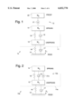
- FIG. 1 illustrates a proof mass actuator system in accordance with the principles of the present invention
- FIG. 2 illustrates a basic differential force actuator system in accordance with the principles of the present invention
- FIG. 3 illustrates the proof mass low force actuator mounted to a vehicle body
- FIG. 4 illustrates the proof mass low force actuator mounted to a vehicle suspension
- FIG. 5 illustrates a differential force low force actuator mounted on a sprung mass of a vehicle
- FIG. 6 illustrates a differential force low force actuator mounted within a suspension system of a vehicle
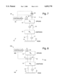
- FIG. 7 illustrates a ride control system using the proof mass low force actuator of FIG. 1;
- FIG. 8 illustrates a ride control system using the differential force low force actuator of FIG. 2;
- FIGS. 9 and 10 illustrate adaptive control systems using proof mass low force actuators in accordance with the present invention.
- FIGS. 11 and 12 illustrate adaptive control system using differential low force actuators in accordance with the present invention.
- the present invention provides for two implementations of low force actuators for use in vehicle suspension systems.
- FIG. 1 illustrates a first suspension system 10 of a vehicle 11 using a proof mass (seismic) low force actuator 12 in accordance with the principles of the present invention.
- FIG. 1 is representative of a single corner of the vehicle 11, basically at the location of one wheel thereof.
- the vehicle 11 comprises an unsprung mass 13 and a sprung mass 14.
- the unsprung mass 13 of the vehicle is comprised of the tire and wheel of the vehicle 11 along with components (suspension and brake components) that are attached thereto.
- the unsprung mass 13 is directly coupled to the road 15 by means of the tires.
- a spring 16 and shock absorber or damper 17 are representative of the tire of the vehicle 11.
- a second spring 18 and shock absorber 19 disposed between the unsprung and sprung masses 13, 14 are representative of the first suspension system 10 of the vehicle 11.
- the proof mass low force actuator 12 is comprised of a linear actuator (A) 21, which is typically an electromagnetic actuator, and a proof mass 22 coupled thereto.
- the proof mass 22 can be a separate mass, but is typically one or more magnets of the actuator 21 as will be described in more detail below.
- the proof mass low force actuator 12 may be coupled to either the sprung or unsprung masses 14, 13. In either configuration the proof mass 22 provides an extra degree of freedom to the first suspension system 10. This means that ride and holding characteristics of the vehicle 11 can be individually controlled at a given corner (tire) of the vehicle 11. In either configuration the proof mass 22 provides an extra degree of freedom for the first suspension system 10. This extra degree of freedom allows the design of a suspension control system that decouples ride and holding control actions of the vehicle 11.
- FIG. 2 illustrates a second suspension system 10a of a vehicle 11a using a differential force low force actuator 12a in accordance with the principles of the present invention.
- the differential force low force actuator 12a uses a linear electromagnetic actuator 21a to provide a force between sprung and unsprung masses 14, 13.
- This implementation is simpler than the first suspension system 10 but ride and holding performance of the vehicle 11a are inversely coupled.
- the second suspension system 10a can only improve ride at the expense of holding, and vice versa, since its reaction force is directly coupled to the vehicle 11a.
- ride control is obtained by commanding the linear actuator 21a to minimize acceleration of the sprung mass 14 (and hence act as a regulator).
- Holding control of the vehicle 11a is obtained by commanding the linear actuator 21a to minimize that component of acceleration of the unsprung mass 13 that is correlated to the acceleration of the sprung mass 14.
- the low force actuators 12, 12a shown in FIGS. 1 and 2 may be added to a conventional passive or semi-active suspension system to overcome stiction and to provide limited active capability for the vehicle 11, 11a.
- the low force actuators 12, 12a are sized to counter the small, high frequency forces (caused by road input disturbances and stiction effects) that act on, or are transmitted between the sprung and unsprung masses 13, 14. These disturbances are annoying and difficult to eliminate using conventional active, semi-active and passive suspension practices.
- a high bandwidth low force actuator as part of the suspension control system, it may be configured to eliminate small high frequency disturbances while mitigating larger disturbances.
- high force actuators 3000-5000 N
- these systems simply do not have the resolution required to control the small disturbance inputs (less than 200 N) that occur most of the time when driving over relatively smooth roads.
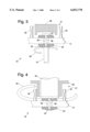
- FIGS. 3 and 4 show proof mass low force actuators 12 integrated into the vehicle 11.
- FIG. 3 illustrates a body-mounted proof mass low force actuator 12 where the low force actuator 12 is mounted above a shock absorber 19 on the sprung mass 14. More particularly, FIG. 3 shows a shaft 31 of the shock absorber 19 which has an upper flange 40 that abuts a rubber bushing 33. An upper portion 38 of the shaft 31 extends through a hole 39 in the sprung mass 14 and is secured thereto by a locking nut 37. A coil spring 32, which forms part of the shock absorber 19 is shown for clarity.
- the linear actuator 21 includes coils 35 and a magnet 36. The magnet 36 is disposed above the sprung mass 14 and is secured to a portion of the vehicle 11. Coils 35 are secured to the sprung mass 14 and are adapted to move with it relative to the magnet 36.
- FIG. 4 illustrates a suspension-mounted proof mass low force actuator 12 where the low force actuator 12 is mounted within the shock absorber 19 on the unsprung mass 13. It is to be understood that this concept may be used to mount the low force actuator 12 on the sprung mass 14. More specifically, FIG. 4 shows a shock housing 30 surrounding the shaft 31 of the shock absorber 19 which has its upper flange 40 abutting the rubber bushing 33. The upper portion 38 of the shaft 31 extends through a hole 39 in the sprung mass 13. The coil spring 32, which forms part of the shock absorber 19 is shown for clarity.
- a magnet 36 is disposed above the unsprung mass 13 outside the shock housing 30 and is secured to a portion of the vehicle 11. Coils 35 are secured to the unsprung mass 13 and are adapted to move with it relative to the magnet 36.
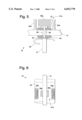
- FIGS. 5 and 6 illustrate two approaches to the integration of the differential force low force actuator 12a in the vehicle 11a.
- FIG. 5 illustrates the differential force low force actuator 12a mounted on the sprung mass 14 of the vehicle 11a, above the suspension system 10a. More particularly, FIG. 5 shows a shaft 31 of the shock absorber 19 which has its upper flange 40 abutting the rubber bushing 33. The upper portion 38 of the shaft 31 extends through the hole 39 in the sprung mass 14 and is secured thereto by the locking nut 37.
- the coil spring 32 which forms part of the shock absorber 19 is shown for clarity.
- the magnet 36a of the linear actuator 21a is disposed above the sprung mass 14 and is secured to the locking nut 37. Coils 35a of the linear actuator 21a are secured to the sprung mass 14 and are adapted to move with it relative to the magnet 36.
- FIG. 6 illustrates the differential force low force actuator 12a mounted within the suspension system 10a of a vehicle 11a.
- the differential force low force actuator 12a is mounted within the shock absorber 19.
- FIG. 6 shows the inside of the shock absorber 19 illustrating the magnet 36a secured to the shaft 31 and the coils 35a secured to an interior wall of the shock housing 30.
- the low force actuator 12a is only effective near a nominal (static equilibrium) position of the suspension system 10 since the magnet 36a may move to a point outside the actuator coils 35a. This is a reasonable design compromise since the low force actuator 12 by its nature (low force) has little capability to effect performance at large suspension loads which imply large deflections.
- the proof mass actuator 12 described above may be controlled to improve ride and/or holding of the vehicle 11. Since reaction forces are absorbed by the proof mass 22, vehicle ride can be improved with minimal impact on holding, and vice versa. To improve ride, the acceleration of the sprung mass 14 is sensed and the linear actuator 21 is commanded to provide a force that opposes the forces exerted on the sprung mass 14 by way of the components of the passive (or semi-active) suspension system 10.
- the low force actuator 12 is commanded so as to minimize variations in the tire-road contact force from its static (equilibrium) value. This is done by sensing accelerations of both the sprung and unsprung masses 14, 13 and commanding the actuator 21 to oppose the accelerations (forces) imposed by the sprung mass 14 on the unsprung mass 13. Thus the unsprung mass 13 (wheel) is free to follow the road 15 to the best of its ability.
- FIGS. 7 and 8 Two basic control system approaches have been developed for use with the low force actuators 12, 12a of the present invention.
- One approach uses conventional control concepts to close ride and/or holding control loop(s) on the suspension system 10, 10a using the proof mass or differential force actuators 12, 12a as is shown in FIGS. 7 and 8. More specifically, FIG. 7 illustrates the first ride control system 24 for the proof mass low force actuator 12, while FIG. 8 illustrates the second ride control system 24a for the differential force actuator 12a. Note, that while a passive suspension system is shown in the drawing figures, the concepts of the present invention are equally applicable to a hybrid suspension system design.
- the first control system 24 for the proof mass low force actuator 12 includes a controller 25 that is coupled to a sensor or accelerometer 23 disposed on the sprung mass 14.
- the controller 25 is also coupled to the proof mass low force actuator 12 which is controlled to oppose the forces exerted on the sprung mass 14 by way of the components of the passive (or semi-active) suspension system 10.
- the second control system 24a (FIG. 8) for the differential actuator 12a includes a controller 25a that is coupled to the sensor or accelerometer 23 disposed on the sprung mass 14.
- the controller 25a is also coupled to the differential force actuator 12a which is controlled to oppose the accelerations (forces) imposed by the sprung mass 14 on the unsprung mass 13.
- FIGS. 9-12 Another approach uses adaptive control to close loops on the suspension system 10, 10a using proof mass or differential force low force actuators 12, 12a as is shown in FIGS. 9-12.
- FIGS. 9 and 10 illustrate adaptive control systems for use with the proof mass low force actuator 12 in accordance with the present invention
- FIGS. 11 and 12 illustrate adaptive control systems use with the differential force low force actuator 12a in accordance with the present invention.
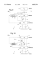
- FIG. 9 shows a control system 124 substantially the same as the system 24 of FIG. 7, but wherein the controller 125 is an adaptive feedback controller.
- the adaptive feedback controller 125 senses the forces on the sprung and unsprung masses 14, 13 by means of two accelerometers 27, 28, and adaptively controls both the linear actuator 21 and the shock absorber 19.
- the adaptive control is based on sensing of the unsprung mass 13.
- FIG. 10 shows a control system 224 that corresponds to the system 24 of FIG. 7, to except that the proof mass low force actuator 12 is disposed on the unsprung mass 13.
- the adaptive feedback controller 225 senses the forces on the sprung and unsprung masses 14, 13 by means of two accelerometers 27, 28, and adaptively controls both the actuator 21 and the shock absorber 19.
- the adaptive control is based on sensing of the sprung mass 14.
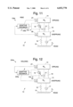
- FIGS. 11 and 12 show control systems 124a, 224a similar to the system 24a of FIG. 8, but wherein the controllers 124a, 224a are adaptive feedback controllers.
- the adaptive feedback controllers 125a, 225a sense the forces on the sprung and unsprung masses 14, 13 by means of two accelerometers 27, 28, and adaptively controls both the actuator 21a and the shock absorber 19.
- adaptive control is based on sensing of the sprung mass 14, while in FIG. 12, adaptive control is based on sensing of the unsprung mass 13.
- the controller is responsive to an output of the accelerometer for controlling the electromagnetic actuator to move the proof mass.
- the proof mass is used to oppose relatively small high frequency forces exerted on the sprung mass.
Landscapes
- Engineering & Computer Science (AREA)
- General Engineering & Computer Science (AREA)
- Physics & Mathematics (AREA)
- Mechanical Engineering (AREA)
- Electromagnetism (AREA)
- Acoustics & Sound (AREA)
- Aviation & Aerospace Engineering (AREA)
- Vehicle Body Suspensions (AREA)
Abstract
Description
Claims (1)
Priority Applications (1)
| Application Number | Priority Date | Filing Date | Title |
|---|---|---|---|
| US08/046,056 US6032770A (en) | 1993-04-12 | 1993-04-12 | Low force actuator for suspension control |
Applications Claiming Priority (1)
| Application Number | Priority Date | Filing Date | Title |
|---|---|---|---|
| US08/046,056 US6032770A (en) | 1993-04-12 | 1993-04-12 | Low force actuator for suspension control |
Publications (1)
| Publication Number | Publication Date |
|---|---|
| US6032770A true US6032770A (en) | 2000-03-07 |
Family
ID=21941345
Family Applications (1)
| Application Number | Title | Priority Date | Filing Date |
|---|---|---|---|
| US08/046,056 Expired - Lifetime US6032770A (en) | 1993-04-12 | 1993-04-12 | Low force actuator for suspension control |
Country Status (1)
| Country | Link |
|---|---|
| US (1) | US6032770A (en) |
Cited By (42)
| Publication number | Priority date | Publication date | Assignee | Title |
|---|---|---|---|---|
| US6181997B1 (en) * | 1999-04-01 | 2001-01-30 | Delphi Technologies, Inc. | Vehicle suspension control with compensation for yaw correcting active brake control |
| US6374968B1 (en) * | 1999-04-22 | 2002-04-23 | Vibrachoc | Resonant device, such as a striker or load generator |
| US6619672B2 (en) * | 2000-10-11 | 2003-09-16 | Conception Et Development Michelin S.A. | Suspension device having a trim corrector |
| US6708094B2 (en) | 2000-10-11 | 2004-03-16 | Michelin Recherche Et Technique S.A. | Suspension device having electric actuator and spring in parallel |
| US20060095180A1 (en) * | 2004-10-29 | 2006-05-04 | Ummethala Upendra V | Active suspending |
| US20060272910A1 (en) * | 2005-06-02 | 2006-12-07 | Emil Kraner | Systems and methods for active vibration damping |
| US20070137954A1 (en) * | 2003-12-17 | 2007-06-21 | Elliott Stephen J | Inertial actuator |
| US20080142633A1 (en) * | 2006-05-06 | 2008-06-19 | Mcguire Dennis | Helicopter reduced vibration isolator axial support strut |
| US20090121444A1 (en) * | 2007-11-12 | 2009-05-14 | Dariusz Antoni Bushko | Vehicle suspension |
| US20100030384A1 (en) * | 2008-07-29 | 2010-02-04 | Technical Manufacturing Corporation | Vibration Isolation System With Design For Offloading Payload Forces Acting on Actuator |
| US20100032543A1 (en) * | 2006-03-01 | 2010-02-11 | Jan Van Der Tempel | Vessel, motion platform, method for compensating motions of a vessel and use of a stewart platform |
| US7665585B2 (en) | 2004-09-03 | 2010-02-23 | Alexandridis Alexander A | Vehicle suspension system and method for operating |
| US8095268B2 (en) | 2004-10-29 | 2012-01-10 | Bose Corporation | Active suspending |
| WO2013107823A1 (en) * | 2012-01-20 | 2013-07-25 | Jaguar Land Rover Limited | Active road noise control system |
| US8899393B2 (en) | 2012-06-08 | 2014-12-02 | Technical Manufacturing Corporation | Active vibration isolation system |
| US20150197131A1 (en) * | 2014-01-15 | 2015-07-16 | Hyundai Mobis Co., Ltd. | Bump shock absorbing device |
| CN108302156A (en) * | 2018-02-06 | 2018-07-20 | 京东方科技集团股份有限公司 | Vibration absorber and conveyer |
| US10065474B2 (en) * | 2016-12-09 | 2018-09-04 | GM Global Technology Operations LLC | Vehicle with suspension force decoupling system |
| CN108709751A (en) * | 2018-05-31 | 2018-10-26 | 华南理工大学 | A kind of teaching test stand and system for indoor automobile ride experiment |
| US10184539B2 (en) | 2014-09-30 | 2019-01-22 | Technical Manufacturing Corporation | Vibration isolation system |
| US10183542B1 (en) | 2017-12-11 | 2019-01-22 | Cnh Industrial America Llc | Suspension control system providing orientation control for an agricultural machine |
| US20190031208A1 (en) * | 2016-01-27 | 2019-01-31 | Ales Tech Srl | Suspension system for levitation vehicles |
| US10295011B2 (en) * | 2017-10-06 | 2019-05-21 | The Boeing Company | Systems and tuned magnetic dashpots for using inductor(s) in magnetic skyhook damper isolation |
| US10436622B2 (en) | 2017-12-11 | 2019-10-08 | Cnh Industrial America Llc | Suspension control system providing closed loop control of hydraulic fluid volumes for an agricultural machine |
| US10569612B2 (en) | 2017-12-11 | 2020-02-25 | Cnh Industrial America Llc | Suspension control system providing tire height corrections for an agricultural machine |
| US10730359B2 (en) | 2017-12-11 | 2020-08-04 | Cnh Industrial America Llc | Suspension control system providing suspension height corrections for an agricultural machine |
| US10814690B1 (en) | 2017-04-18 | 2020-10-27 | Apple Inc. | Active suspension system with energy storage device |
| US10899340B1 (en) | 2017-06-21 | 2021-01-26 | Apple Inc. | Vehicle with automated subsystems |
| US10906370B1 (en) | 2017-09-15 | 2021-02-02 | Apple Inc. | Active suspension system |
| US10960723B1 (en) | 2017-09-26 | 2021-03-30 | Apple Inc. | Wheel-mounted suspension actuators |
| US11046143B1 (en) | 2015-03-18 | 2021-06-29 | Apple Inc. | Fully-actuated suspension system |
| US11124035B1 (en) | 2017-09-25 | 2021-09-21 | Apple Inc. | Multi-stage active suspension actuator |
| US11173766B1 (en) | 2017-09-07 | 2021-11-16 | Apple Inc. | Suspension system with locking structure |
| US11179991B1 (en) | 2019-09-23 | 2021-11-23 | Apple Inc. | Suspension systems |
| US11285773B1 (en) | 2018-09-12 | 2022-03-29 | Apple Inc. | Control system |
| US11345209B1 (en) | 2019-06-03 | 2022-05-31 | Apple Inc. | Suspension systems |
| US11358431B2 (en) | 2017-05-08 | 2022-06-14 | Apple Inc. | Active suspension system |
| US11512757B2 (en) | 2017-08-15 | 2022-11-29 | Technical Manufacturing Coporation | Precision vibration-isolation system with floor feedforward assistance |
| US11634167B1 (en) | 2018-09-14 | 2023-04-25 | Apple Inc. | Transmitting axial and rotational movement to a hub |
| US11707961B1 (en) | 2020-04-28 | 2023-07-25 | Apple Inc. | Actuator with reinforcing structure for torsion resistance |
| US11828339B1 (en) | 2020-07-07 | 2023-11-28 | Apple Inc. | Vibration control system |
| US11938922B1 (en) | 2019-09-23 | 2024-03-26 | Apple Inc. | Motion control system |
Citations (8)
| Publication number | Priority date | Publication date | Assignee | Title |
|---|---|---|---|---|
| US3807678A (en) * | 1972-09-19 | 1974-04-30 | Lord Corp | System for controlling the transmission of energy between spaced members |
| US4749210A (en) * | 1985-09-27 | 1988-06-07 | Nissan Motor Company, Limited | Automotive suspension control system with manually adjustable suspension characteristics and/or suspension control characteristics |
| US4776610A (en) * | 1986-12-01 | 1988-10-11 | Moog Inc. | Short-stroke position transducer for a vehicle suspension system |
| US4809179A (en) * | 1987-01-20 | 1989-02-28 | Ford Motor Company | Control system for motor vehicle suspension unit |
| US4887699A (en) * | 1989-02-10 | 1989-12-19 | Lord Corporation | Vibration attenuating method utilizing continuously variable semiactive damper |
| US4981309A (en) * | 1989-08-31 | 1991-01-01 | Bose Corporation | Electromechanical transducing along a path |
| US5174598A (en) * | 1990-11-30 | 1992-12-29 | Nissan Motor Co., Ltd. | Active suspension system |
| US5217246A (en) * | 1989-04-24 | 1993-06-08 | Group Lotus Plc | Control system for controlling the suspension of a land vehicle |
-
1993
- 1993-04-12 US US08/046,056 patent/US6032770A/en not_active Expired - Lifetime
Patent Citations (8)
| Publication number | Priority date | Publication date | Assignee | Title |
|---|---|---|---|---|
| US3807678A (en) * | 1972-09-19 | 1974-04-30 | Lord Corp | System for controlling the transmission of energy between spaced members |
| US4749210A (en) * | 1985-09-27 | 1988-06-07 | Nissan Motor Company, Limited | Automotive suspension control system with manually adjustable suspension characteristics and/or suspension control characteristics |
| US4776610A (en) * | 1986-12-01 | 1988-10-11 | Moog Inc. | Short-stroke position transducer for a vehicle suspension system |
| US4809179A (en) * | 1987-01-20 | 1989-02-28 | Ford Motor Company | Control system for motor vehicle suspension unit |
| US4887699A (en) * | 1989-02-10 | 1989-12-19 | Lord Corporation | Vibration attenuating method utilizing continuously variable semiactive damper |
| US5217246A (en) * | 1989-04-24 | 1993-06-08 | Group Lotus Plc | Control system for controlling the suspension of a land vehicle |
| US4981309A (en) * | 1989-08-31 | 1991-01-01 | Bose Corporation | Electromechanical transducing along a path |
| US5174598A (en) * | 1990-11-30 | 1992-12-29 | Nissan Motor Co., Ltd. | Active suspension system |
Cited By (64)
| Publication number | Priority date | Publication date | Assignee | Title |
|---|---|---|---|---|
| US6181997B1 (en) * | 1999-04-01 | 2001-01-30 | Delphi Technologies, Inc. | Vehicle suspension control with compensation for yaw correcting active brake control |
| US6374968B1 (en) * | 1999-04-22 | 2002-04-23 | Vibrachoc | Resonant device, such as a striker or load generator |
| US6619672B2 (en) * | 2000-10-11 | 2003-09-16 | Conception Et Development Michelin S.A. | Suspension device having a trim corrector |
| US6708094B2 (en) | 2000-10-11 | 2004-03-16 | Michelin Recherche Et Technique S.A. | Suspension device having electric actuator and spring in parallel |
| US20070137954A1 (en) * | 2003-12-17 | 2007-06-21 | Elliott Stephen J | Inertial actuator |
| US7665585B2 (en) | 2004-09-03 | 2010-02-23 | Alexandridis Alexander A | Vehicle suspension system and method for operating |
| US20060095180A1 (en) * | 2004-10-29 | 2006-05-04 | Ummethala Upendra V | Active suspending |
| US8548678B2 (en) | 2004-10-29 | 2013-10-01 | Bose Corporation | Active suspending |
| US8095268B2 (en) | 2004-10-29 | 2012-01-10 | Bose Corporation | Active suspending |
| US7983813B2 (en) | 2004-10-29 | 2011-07-19 | Bose Corporation | Active suspending |
| US20100320357A1 (en) * | 2004-10-29 | 2010-12-23 | Ummethala Upendra V | Active suspending |
| US20060272910A1 (en) * | 2005-06-02 | 2006-12-07 | Emil Kraner | Systems and methods for active vibration damping |
| US7726452B2 (en) * | 2005-06-02 | 2010-06-01 | Technical Manufacturing Corporation | Systems and methods for active vibration damping |
| US20100032543A1 (en) * | 2006-03-01 | 2010-02-11 | Jan Van Der Tempel | Vessel, motion platform, method for compensating motions of a vessel and use of a stewart platform |
| US9174710B2 (en) | 2006-03-01 | 2015-11-03 | Ampelmann Holding B.V. | Vessel, motion platform, method for compensating motions of a vessel and use of a Stewart platform |
| US8672288B2 (en) * | 2006-03-01 | 2014-03-18 | Ampelmann Holding B.V. | Vessel, motion platform, method for compensating motions of a vessel and use of a Stewart platform |
| US9487277B2 (en) | 2006-03-01 | 2016-11-08 | Ampelmann Holding B.V. | Vessel, motion platform, method for compensating motions of a vessel and use of a Stewart platform |
| US8113321B2 (en) | 2006-05-06 | 2012-02-14 | Lord Corporation | Helicopter reduced vibration isolator axial support strut |
| US20080142633A1 (en) * | 2006-05-06 | 2008-06-19 | Mcguire Dennis | Helicopter reduced vibration isolator axial support strut |
| US7962261B2 (en) | 2007-11-12 | 2011-06-14 | Bose Corporation | Vehicle suspension |
| US20090121444A1 (en) * | 2007-11-12 | 2009-05-14 | Dariusz Antoni Bushko | Vehicle suspension |
| US20100030384A1 (en) * | 2008-07-29 | 2010-02-04 | Technical Manufacturing Corporation | Vibration Isolation System With Design For Offloading Payload Forces Acting on Actuator |
| WO2013107823A1 (en) * | 2012-01-20 | 2013-07-25 | Jaguar Land Rover Limited | Active road noise control system |
| GB2499978B (en) * | 2012-01-20 | 2014-11-05 | Jaguar Land Rover Ltd | Active road noise control system |
| CN104245371A (en) * | 2012-01-20 | 2014-12-24 | 捷豹路虎有限公司 | Active road noise control system |
| US9278600B2 (en) | 2012-01-20 | 2016-03-08 | Jaguar Land Rover Limited | Active road noise control system |
| US8899393B2 (en) | 2012-06-08 | 2014-12-02 | Technical Manufacturing Corporation | Active vibration isolation system |
| US9353824B2 (en) | 2012-06-08 | 2016-05-31 | Technical Manufacturing Corporation | Active vibration isolation system |
| US9428024B2 (en) * | 2014-01-15 | 2016-08-30 | Hyundai Mobis Co., Ltd. | Bump shock absorbing device |
| US20150197131A1 (en) * | 2014-01-15 | 2015-07-16 | Hyundai Mobis Co., Ltd. | Bump shock absorbing device |
| US10808790B2 (en) | 2014-09-30 | 2020-10-20 | Technical Manufacturing Corporation | Vibration isolation system |
| US10184539B2 (en) | 2014-09-30 | 2019-01-22 | Technical Manufacturing Corporation | Vibration isolation system |
| US11945279B1 (en) | 2015-03-18 | 2024-04-02 | Apple Inc. | Motion control system |
| US11046143B1 (en) | 2015-03-18 | 2021-06-29 | Apple Inc. | Fully-actuated suspension system |
| US11059499B2 (en) * | 2016-01-27 | 2021-07-13 | Ales Tech Srl | Suspension system for levitation vehicles |
| US20190031208A1 (en) * | 2016-01-27 | 2019-01-31 | Ales Tech Srl | Suspension system for levitation vehicles |
| US10065474B2 (en) * | 2016-12-09 | 2018-09-04 | GM Global Technology Operations LLC | Vehicle with suspension force decoupling system |
| US10814690B1 (en) | 2017-04-18 | 2020-10-27 | Apple Inc. | Active suspension system with energy storage device |
| US11701942B2 (en) | 2017-05-08 | 2023-07-18 | Apple Inc. | Motion control system |
| US11358431B2 (en) | 2017-05-08 | 2022-06-14 | Apple Inc. | Active suspension system |
| US11702065B1 (en) | 2017-06-21 | 2023-07-18 | Apple Inc. | Thermal management system control |
| US10899340B1 (en) | 2017-06-21 | 2021-01-26 | Apple Inc. | Vehicle with automated subsystems |
| US11873880B2 (en) | 2017-08-15 | 2024-01-16 | Technical Manufacturing Corporation | Precision vibration-isolation system with floor feedforward assistance |
| US11512757B2 (en) | 2017-08-15 | 2022-11-29 | Technical Manufacturing Coporation | Precision vibration-isolation system with floor feedforward assistance |
| US11173766B1 (en) | 2017-09-07 | 2021-11-16 | Apple Inc. | Suspension system with locking structure |
| US10906370B1 (en) | 2017-09-15 | 2021-02-02 | Apple Inc. | Active suspension system |
| US11065931B1 (en) | 2017-09-15 | 2021-07-20 | Apple Inc. | Active suspension system |
| US11124035B1 (en) | 2017-09-25 | 2021-09-21 | Apple Inc. | Multi-stage active suspension actuator |
| US10960723B1 (en) | 2017-09-26 | 2021-03-30 | Apple Inc. | Wheel-mounted suspension actuators |
| US10295011B2 (en) * | 2017-10-06 | 2019-05-21 | The Boeing Company | Systems and tuned magnetic dashpots for using inductor(s) in magnetic skyhook damper isolation |
| US10730359B2 (en) | 2017-12-11 | 2020-08-04 | Cnh Industrial America Llc | Suspension control system providing suspension height corrections for an agricultural machine |
| US10183542B1 (en) | 2017-12-11 | 2019-01-22 | Cnh Industrial America Llc | Suspension control system providing orientation control for an agricultural machine |
| US10436622B2 (en) | 2017-12-11 | 2019-10-08 | Cnh Industrial America Llc | Suspension control system providing closed loop control of hydraulic fluid volumes for an agricultural machine |
| US10569612B2 (en) | 2017-12-11 | 2020-02-25 | Cnh Industrial America Llc | Suspension control system providing tire height corrections for an agricultural machine |
| CN108302156A (en) * | 2018-02-06 | 2018-07-20 | 京东方科技集团股份有限公司 | Vibration absorber and conveyer |
| CN108709751A (en) * | 2018-05-31 | 2018-10-26 | 华南理工大学 | A kind of teaching test stand and system for indoor automobile ride experiment |
| US11285773B1 (en) | 2018-09-12 | 2022-03-29 | Apple Inc. | Control system |
| US11634167B1 (en) | 2018-09-14 | 2023-04-25 | Apple Inc. | Transmitting axial and rotational movement to a hub |
| US11345209B1 (en) | 2019-06-03 | 2022-05-31 | Apple Inc. | Suspension systems |
| US11179991B1 (en) | 2019-09-23 | 2021-11-23 | Apple Inc. | Suspension systems |
| US11731476B1 (en) | 2019-09-23 | 2023-08-22 | Apple Inc. | Motion control systems |
| US11938922B1 (en) | 2019-09-23 | 2024-03-26 | Apple Inc. | Motion control system |
| US11707961B1 (en) | 2020-04-28 | 2023-07-25 | Apple Inc. | Actuator with reinforcing structure for torsion resistance |
| US11828339B1 (en) | 2020-07-07 | 2023-11-28 | Apple Inc. | Vibration control system |
Similar Documents
| Publication | Publication Date | Title |
|---|---|---|
| US6032770A (en) | Low force actuator for suspension control | |
| EP0538965B1 (en) | Vibration attenuating method utilizing continuously variable semiactive damper | |
| US4154461A (en) | Automobile suspension system | |
| US5004079A (en) | Semi-active damper valve means and method | |
| EP0313708B1 (en) | Shock absorber | |
| EP0290181B1 (en) | Vehicle engine suspension systems | |
| US4936425A (en) | Method of operating a vibration attenuating system having semiactive damper means | |
| EP0249227B1 (en) | Actively controlled automotive suspension system with mutually independent hydraulic systems having mutually different damping characteristics for improving response characteristics in active suspension control | |
| US4960290A (en) | Wheel assembly suspending | |
| US5428533A (en) | Suspension control system with variable damp and spring coefficients | |
| Yokoyama et al. | A model following sliding mode controller for semi-active suspension systems with MR dampers | |
| US5732370A (en) | Method for controlling motion using a two-stage adjustable damper | |
| US5721681A (en) | Arrangement for control of a chassis vibration damping device | |
| EP0277259B1 (en) | A variable rate shock absorber | |
| EP0739766A2 (en) | Method for controlling motion using an adjustable damper | |
| Kim et al. | Vibration suppression in an MR fluid damper suspension system | |
| US9365089B2 (en) | Method and apparatus for active suspension damping including negative stiffness | |
| US20150167770A1 (en) | Method and apparatus for suspension damping including negative stiffness employing a permanent magnet | |
| US5390948A (en) | Active vehicle suspension system and a control method therefor | |
| CN107618408B (en) | Automobile seat damping device based on magnetorheological fluid material and automobile | |
| CN105221642A (en) | A kind of shock-dampening method, damping device and application thereof | |
| US6148252A (en) | Automotive suspension control system utilizing variable damping force shock absorber | |
| EP0397702B1 (en) | A variable rate shock absorber and system therefor | |
| JP2823963B2 (en) | Hydraulic damper | |
| US5489115A (en) | Active suspension system |
Legal Events
| Date | Code | Title | Description |
|---|---|---|---|
| AS | Assignment |
Owner name: HUGHES AIRCRAFT COMPANY, CALIFORNIA Free format text: ASSIGNMENT OF ASSIGNORS INTEREST.;ASSIGNORS:ALCONE, JERRY M.;LOHNES, KIRK A.;JETER, JAMES W.;REEL/FRAME:006513/0366;SIGNING DATES FROM 19930309 TO 19930402 |
|
| STPP | Information on status: patent application and granting procedure in general |
Free format text: APPLICATION UNDERGOING PREEXAM PROCESSING |
|
| FEPP | Fee payment procedure |
Free format text: PAYOR NUMBER ASSIGNED (ORIGINAL EVENT CODE: ASPN); ENTITY STATUS OF PATENT OWNER: LARGE ENTITY |
|
| FPAY | Fee payment |
Year of fee payment: 4 |
|
| REMI | Maintenance fee reminder mailed | ||
| AS | Assignment |
Owner name: HE HOLDINGS, INC., A DELAWARE CORP., CALIFORNIA Free format text: CHANGE OF NAME;ASSIGNOR:HUGHES AIRCRAFT COMPANY, A CORPORATION OF THE STATE OF DELAWARE;REEL/FRAME:016087/0541 Effective date: 19971217 Owner name: RAYTHEON COMPANY, MASSACHUSETTS Free format text: MERGER;ASSIGNOR:HE HOLDINGS, INC. DBA HUGHES ELECTRONICS;REEL/FRAME:016116/0506 Effective date: 19971217 |
|
| FPAY | Fee payment |
Year of fee payment: 8 |
|
| FPAY | Fee payment |
Year of fee payment: 12 |
|
| FEPP | Fee payment procedure |
Free format text: PAYOR NUMBER ASSIGNED (ORIGINAL EVENT CODE: ASPN); ENTITY STATUS OF PATENT OWNER: LARGE ENTITY Free format text: PAYER NUMBER DE-ASSIGNED (ORIGINAL EVENT CODE: RMPN); ENTITY STATUS OF PATENT OWNER: LARGE ENTITY |
|
| AS | Assignment |
Owner name: OL SECURITY LIMITED LIABILITY COMPANY, DELAWARE Free format text: ASSIGNMENT OF ASSIGNORS INTEREST;ASSIGNOR:RAYTHEON COMPANY;REEL/FRAME:029117/0335 Effective date: 20120730 |
|
| AS | Assignment |
Owner name: HANGER SOLUTIONS, LLC, GEORGIA Free format text: ASSIGNMENT OF ASSIGNORS INTEREST;ASSIGNOR:INTELLECTUAL VENTURES ASSETS 158 LLC;REEL/FRAME:051486/0425 Effective date: 20191206 |
|
| AS | Assignment |
Owner name: INTELLECTUAL VENTURES ASSETS 158 LLC, DELAWARE Free format text: ASSIGNMENT OF ASSIGNORS INTEREST;ASSIGNOR:OL SECURITY LIMITED LIABILITY COMPANY;REEL/FRAME:051846/0192 Effective date: 20191126 |