US6032718A - Adjustable sunshade for an automobile - Google Patents
Adjustable sunshade for an automobile Download PDFInfo
- Publication number
- US6032718A US6032718A US09/324,204 US32420499A US6032718A US 6032718 A US6032718 A US 6032718A US 32420499 A US32420499 A US 32420499A US 6032718 A US6032718 A US 6032718A
- Authority
- US
- United States
- Prior art keywords
- ratchet
- sunshade
- curtain
- automobile
- winder
- Prior art date
- Legal status (The legal status is an assumption and is not a legal conclusion. Google has not performed a legal analysis and makes no representation as to the accuracy of the status listed.)
- Expired - Fee Related
Links
Images
Classifications
-
- B—PERFORMING OPERATIONS; TRANSPORTING
- B60—VEHICLES IN GENERAL
- B60J—WINDOWS, WINDSCREENS, NON-FIXED ROOFS, DOORS, OR SIMILAR DEVICES FOR VEHICLES; REMOVABLE EXTERNAL PROTECTIVE COVERINGS SPECIALLY ADAPTED FOR VEHICLES
- B60J1/00—Windows; Windscreens; Accessories therefor
- B60J1/20—Accessories, e.g. wind deflectors, blinds
- B60J1/2011—Blinds; curtains or screens reducing heat or light intensity
- B60J1/2013—Roller blinds
- B60J1/2019—Roller blinds powered, e.g. by electric, hydraulic or pneumatic actuators
-
- B—PERFORMING OPERATIONS; TRANSPORTING
- B60—VEHICLES IN GENERAL
- B60J—WINDOWS, WINDSCREENS, NON-FIXED ROOFS, DOORS, OR SIMILAR DEVICES FOR VEHICLES; REMOVABLE EXTERNAL PROTECTIVE COVERINGS SPECIALLY ADAPTED FOR VEHICLES
- B60J1/00—Windows; Windscreens; Accessories therefor
- B60J1/20—Accessories, e.g. wind deflectors, blinds
- B60J1/2011—Blinds; curtains or screens reducing heat or light intensity
- B60J1/2013—Roller blinds
- B60J1/2036—Roller blinds characterised by structural elements
- B60J1/2055—Pivoting arms
-
- B—PERFORMING OPERATIONS; TRANSPORTING
- B60—VEHICLES IN GENERAL
- B60J—WINDOWS, WINDSCREENS, NON-FIXED ROOFS, DOORS, OR SIMILAR DEVICES FOR VEHICLES; REMOVABLE EXTERNAL PROTECTIVE COVERINGS SPECIALLY ADAPTED FOR VEHICLES
- B60J1/00—Windows; Windscreens; Accessories therefor
- B60J1/20—Accessories, e.g. wind deflectors, blinds
- B60J1/2011—Blinds; curtains or screens reducing heat or light intensity
- B60J1/2013—Roller blinds
- B60J1/2066—Arrangement of blinds in vehicles
- B60J1/2075—Arrangement of blinds in vehicles specially adapted for fixed windows
- B60J1/208—Arrangement of blinds in vehicles specially adapted for fixed windows for rear windows
Definitions
- the present invention relates to an adjustable sunshade for an automobile, and more particularly to a sunshade that is mounted on the rear window of an automobile and can be adjusted to adapt to various kinds of rear windows with different angles.
- a sunshade is usually provided for an automobile to keep out the sunshine.
- a conventional sunshade is a curtain directly mounted on the windows by suction cups or other attachment devices. This sunshade is inconvenient to use as the curtain has to be removed when not in use and installed again when in use. Therefore, an electric sunshade was invented for operator convenience.
- the electric sunshade is generally mounted below or at the bottom of the rear window.
- the electric sunshade comprises a base stably mounted below the rear window; a body provided in the base and having a curtain wound thereon; two arms pivotally mounted on both ends of the body and attached to the curtain and driven by a motor.
- the motor drives outward, the arms swing out from the body, and the curtain is extended.
- the motor drives inward, the arms swing toward the body, and the curtain is folded.
- the sunshade must be adjustable to adapt to these windows.
- the body is pivotally mounted on the base and fixed by wing nuts. To release the wing nuts, the body can be pivoted to adjust the angle between the arms and the base. The wing nuts are then tightened again to fix the arms.
- this sunshade is also inconvenient to mount and use. Furthermore, the sunshade has a repulsive appearance as the elements are all exposed.
- An adjustable electric sunshade in accordance with the present invention tends to mitigate and/or obviate the aforementioned problems.
- the main object of the present invention is to provide an adjustable sunshade for an automobile that is easy to adjust the angle between the curtain and the rear window.
- Another object of the present invention is to provide an adjustable sunshade for an automobile that has an attractive appearance.
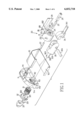
- FIG. 1 is a partial exploded perspective view of a sunshade according to the present invention
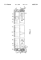
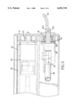
- FIG. 2 is a sectional plan view of the sunshade according to the present invention.
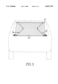
- FIG. 3 is a schematic view of the sunshade mounted on the rear window of a automobile
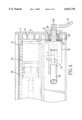
- FIG. 4 is a partial sectional view of a first ratchet engaged with a second ratchet of the sunshade in accordance with the present invention
- FIG. 5 is a partial sectional view of the first ratchet being disengaged from the second ratchet of the sunshade in accordance with the present invention.
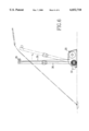
- FIG. 6 is a side view showing the adjustment of the flexible arms in accordance with the present invention.
- the sunshade in accordance with the present invention comprises a hollow housing (10) with a gap (101) defined therein.
- Two covers (11) are respectively mounted on both sides of the housing (10).
- the cover (11) comprises a positioning base (111) formed in the inside rear portion and a first ratchet (112) formed on the inside front portion.
- a winder (20) is provided between the two positioning bases (111).
- the winder (20) comprises a roller (21), a supporting roller (27) and a motor (23).
- the roller (21) has a fixing hole (212) defined in one end and a receiving hole (211) defined the other end.
- a pin (22) is received between the fixing hole (212) and the positioning base (111) to be pivotally mounted on one of the covers (11).
- One end of a rod (25) is inserted into the receiving hole (211), and the other end is connected to a tube (26).
- the motor (23) is mounted on the other positioning base (111).
- a shaft (231) extending from the motor (23) is received in another tube (24).
- the supporting roller (27) is provided between the tubes (24, 26).
- the roller (21), the supporting roller (27) and the motor (23) respectively have slots (213) aligned with each other.
- Multiple lugs (214, 215) are formed in the slots (213).
- a fixed slat (28) for a curtain (29) defines apertures (281, 282) corresponding to these lugs (214) in the slots (213).
- the fixed slat (28) is received in the slots (213) and the lugs (214) are inserted through the apertures (281). After that, the lugs (214) are riveted and the fixed slat (28) is fastened within the slots (213).
- the curtain (29) further comprises an unfixed slat (35) provided at the other end of the curtain (29), as shown in FIG. 3. When the motor (23) turns, the curtain (29) can be wound on the winder (20).
- the cover (11) defines a recess (114) having a flange (115) formed coaxial with the first ratchet (112) therein.
- the flange (115) defines a through hole (113) in the first ratchet (112).
- An elbow (30) having a finger (302) on one end and a joint (34) pivotally connected to the other end by a pivot pin (304) is able to be inserted into the through hole (113).
- the finger (302) is inserted into the through hole (113) and extend out from the flange (115).
- a second ratchet (301) is formed on the surface of the elbow (30) opposite to the first ratchet (112) and engages the first ratchet (112). Thereby, the elbow (30) cannot be turned when the first ratchet (112) is engaged with the second ratchet (301).
- a spring (31) is disposed around the flange (115).
- a plug (32) having a rib (321) formed thereon and an opening (322) centrally defined in the rib (321) is mounted on the cover (11) by inserting the rib (321) into the recess (114) to prevent the spring from escaping.
- the finger (302) also extends out from the opening (322).
- the finger (302) further comprises a pin aperture (303) defined adjacent the distal end.
- a U-shaped handle (33) is pivotally attached to the finger (302) by engaging a pin (not numbered or shown) into the pin aperture (303) and the corresponding apertures (not numbered) of the handle (33).
- the joint (34) is pivotally mounted the other end of the elbow (30) by a pin (304).
- a pole (341) is provided in the joint (34) and the distal end of the pole (341) is connected to a flexible arm (36).
- another end of the flexible arm (36) is attached to the unfixed slat (35) of the curtain (29).
- the flexible arm (36) is located within the gap (101) of the housing (10) and has an upward flexibility, the curtain (29) is pulled out from the gap (101) and can be extended.
- the U-shaped handle (33) further forms a protrusion (331) at the connecting portion.
- the protrusion (331) of the handle (33) presses the plug (32) to ensure the first and second ratchet (112, 301) stay engaged with each other.
- the elbow (30) can not be turned. If a user tends to adjust the angle of the curtain (29), the handle (33) is pivoted outwards to separate the protrusion (331) from the plug (32), as shown in FIG. 5. Then, the elbow (30) can be slightly moved inwards so that the first ratchet (112) disengages from the second ratchet (301). Thereby, the user can turn the handle (33) to adjust the angle of the flexible arm (36). After the adjustment is completed, the handle (33) is pivoted to the original position. The protrusion (331) presses the plug (32), and the first ratchet (112) engages the second ratchet (302) again.
- the angle the curtain can be easily adjusted by turning the handle.
Abstract
An adjustable electric sunshade for an automobile has a hollow housing; two covers respectively provided on the both sides of the housing and each having a first ratchet formed therein; a winder provided in the housing and driven by a motor; two elbows pivotally mounted in the housing and each having a second ratchet opposing the first ratchet; two handles respectively pivotally mounted on fingers of the elbows extending out from the covers and each having a protrusion which can ensure the engagement of the first and second ratchets; two flexible arms respectively provided on the elbows; a curtain wound on the winder on one end and attached to the flexible arms on another end. The curtain can be extended by the flexible arms. Turning the handles to release the protrusions can disengage the first ratchet from the second ratchet, so that the elbows can be pivoted to adjust the curtain's angle. By this, the sunshade can be adapted to various rear windows.
Description
1. Field of the Invention
The present invention relates to an adjustable sunshade for an automobile, and more particularly to a sunshade that is mounted on the rear window of an automobile and can be adjusted to adapt to various kinds of rear windows with different angles.
2. Description of Related Art
A sunshade is usually provided for an automobile to keep out the sunshine. A conventional sunshade is a curtain directly mounted on the windows by suction cups or other attachment devices. This sunshade is inconvenient to use as the curtain has to be removed when not in use and installed again when in use. Therefore, an electric sunshade was invented for operator convenience.
The electric sunshade is generally mounted below or at the bottom of the rear window. The electric sunshade comprises a base stably mounted below the rear window; a body provided in the base and having a curtain wound thereon; two arms pivotally mounted on both ends of the body and attached to the curtain and driven by a motor. When the motor drives outward, the arms swing out from the body, and the curtain is extended. When the motor drives inward, the arms swing toward the body, and the curtain is folded.
Because various automobiles' rear windows have different angles, the sunshade must be adjustable to adapt to these windows. In this electric sunshade, the body is pivotally mounted on the base and fixed by wing nuts. To release the wing nuts, the body can be pivoted to adjust the angle between the arms and the base. The wing nuts are then tightened again to fix the arms. However, this sunshade is also inconvenient to mount and use. Furthermore, the sunshade has a repulsive appearance as the elements are all exposed.
An adjustable electric sunshade in accordance with the present invention tends to mitigate and/or obviate the aforementioned problems.
The main object of the present invention is to provide an adjustable sunshade for an automobile that is easy to adjust the angle between the curtain and the rear window.
Another object of the present invention is to provide an adjustable sunshade for an automobile that has an attractive appearance.
Other objects, advantages and novel features of the invention will become more apparent from the following detailed description when taken in conjunction with the accompanying drawings.
FIG. 1 is a partial exploded perspective view of a sunshade according to the present invention;
FIG. 2 is a sectional plan view of the sunshade according to the present invention;
FIG. 3 is a schematic view of the sunshade mounted on the rear window of a automobile;
FIG. 4 is a partial sectional view of a first ratchet engaged with a second ratchet of the sunshade in accordance with the present invention;
FIG. 5 is a partial sectional view of the first ratchet being disengaged from the second ratchet of the sunshade in accordance with the present invention; and
FIG. 6 is a side view showing the adjustment of the flexible arms in accordance with the present invention.
Referring to FIGS. 1 and 2, the sunshade in accordance with the present invention comprises a hollow housing (10) with a gap (101) defined therein. Two covers (11) are respectively mounted on both sides of the housing (10). The cover (11) comprises a positioning base (111) formed in the inside rear portion and a first ratchet (112) formed on the inside front portion.
A winder (20) is provided between the two positioning bases (111). The winder (20) comprises a roller (21), a supporting roller (27) and a motor (23). The roller (21) has a fixing hole (212) defined in one end and a receiving hole (211) defined the other end. A pin (22) is received between the fixing hole (212) and the positioning base (111) to be pivotally mounted on one of the covers (11). One end of a rod (25) is inserted into the receiving hole (211), and the other end is connected to a tube (26). The motor (23) is mounted on the other positioning base (111). A shaft (231) extending from the motor (23) is received in another tube (24). The supporting roller (27) is provided between the tubes (24, 26).
The roller (21), the supporting roller (27) and the motor (23) respectively have slots (213) aligned with each other. Multiple lugs (214, 215) are formed in the slots (213). A fixed slat (28) for a curtain (29) defines apertures (281, 282) corresponding to these lugs (214) in the slots (213). The fixed slat (28) is received in the slots (213) and the lugs (214) are inserted through the apertures (281). After that, the lugs (214) are riveted and the fixed slat (28) is fastened within the slots (213). The curtain (29) further comprises an unfixed slat (35) provided at the other end of the curtain (29), as shown in FIG. 3. When the motor (23) turns, the curtain (29) can be wound on the winder (20).
The cover (11) defines a recess (114) having a flange (115) formed coaxial with the first ratchet (112) therein. The flange (115) defines a through hole (113) in the first ratchet (112). An elbow (30) having a finger (302) on one end and a joint (34) pivotally connected to the other end by a pivot pin (304) is able to be inserted into the through hole (113). The finger (302) is inserted into the through hole (113) and extend out from the flange (115). A second ratchet (301) is formed on the surface of the elbow (30) opposite to the first ratchet (112) and engages the first ratchet (112). Thereby, the elbow (30) cannot be turned when the first ratchet (112) is engaged with the second ratchet (301).
A spring (31) is disposed around the flange (115). A plug (32) having a rib (321) formed thereon and an opening (322) centrally defined in the rib (321) is mounted on the cover (11) by inserting the rib (321) into the recess (114) to prevent the spring from escaping. The finger (302) also extends out from the opening (322). The finger (302) further comprises a pin aperture (303) defined adjacent the distal end. A U-shaped handle (33) is pivotally attached to the finger (302) by engaging a pin (not numbered or shown) into the pin aperture (303) and the corresponding apertures (not numbered) of the handle (33).
The joint (34) is pivotally mounted the other end of the elbow (30) by a pin (304). A pole (341) is provided in the joint (34) and the distal end of the pole (341) is connected to a flexible arm (36). Referring to FIG. 3, another end of the flexible arm (36) is attached to the unfixed slat (35) of the curtain (29). The flexible arm (36) is located within the gap (101) of the housing (10) and has an upward flexibility, the curtain (29) is pulled out from the gap (101) and can be extended.
Referring to FIG. 4, the U-shaped handle (33) further forms a protrusion (331) at the connecting portion. The protrusion (331) of the handle (33) presses the plug (32) to ensure the first and second ratchet (112, 301) stay engaged with each other. In this case, the elbow (30) can not be turned. If a user tends to adjust the angle of the curtain (29), the handle (33) is pivoted outwards to separate the protrusion (331) from the plug (32), as shown in FIG. 5. Then, the elbow (30) can be slightly moved inwards so that the first ratchet (112) disengages from the second ratchet (301). Thereby, the user can turn the handle (33) to adjust the angle of the flexible arm (36). After the adjustment is completed, the handle (33) is pivoted to the original position. The protrusion (331) presses the plug (32), and the first ratchet (112) engages the second ratchet (302) again.
The advantages of the present invention are:
1. The angle the curtain can be easily adjusted by turning the handle.
2. Most of elements are hidden in the housing and only the handles are exposed, so the sunshade has an attractive appearance.
It is to be understood, however, even though numerous characteristics and advantages of the present invention have been set forth in the foregoing description, together with details of the structure and function of the invention, the disclosure is illustrative only, and changes may be made in detail, especially in matters of shape, size, and arrangement of parts within the principles of the invention to the full extent indicated by the broad general meaning of the terms in which the appended claims are expressed.
Claims (3)
1. An adjustable sunshade for as automobile comprising:
a hollow housing with a gap defined therein;
two covers respectively mounted on both sides of the housing and each having:
a positioning base formed in the inside thereof;
a first ratchet formed in the inside thereof and located in the gap;
a recess defined in the outside thereof and aligned with the first ratchet;
a flange formed in the recess; and
a through hole defined in the flange;
a winder pivotally mounted on the positioning base and between the two covers;
a curtain having a fixed slat fixed on the winder and an unfixed slat attached to two flexible arms;
two elbows oppositely located in the gap, each having:
a second ratchet formed in a surface opposite to the first ratchet;
a finger formed in the surface and inserted into the through hole; and
a joint to pivotally mount the flexible arm on the elbow;
two springs respectively disposed around the flange in the recess;
two plugs respectively to cover the recess and having an opening for the finger inserting through; and
two handles respectively pivotally mounted on the finger and forming a protrusion, wherein the protrusion can press the plug to engage the first ratchet to the second ratchet when pivoting the handle.
2. The sunshade for an automobile claimed in claim 1, wherein the winder further has a roller pivotally mounted on the positioning base at one side by a pin, a motor provided on the positioning base at another side; and a supporting roller provided between the roller and the motor.
3. The sunshade for an automobile claimed in claim 2, wherein the roller, the supporting roller and the motor all define a slot in their periphery, and the fixed slat of the curtain is fastened in the slot.
Priority Applications (1)
| Application Number | Priority Date | Filing Date | Title |
|---|---|---|---|
| US09/324,204 US6032718A (en) | 1999-06-02 | 1999-06-02 | Adjustable sunshade for an automobile |
Applications Claiming Priority (1)
| Application Number | Priority Date | Filing Date | Title |
|---|---|---|---|
| US09/324,204 US6032718A (en) | 1999-06-02 | 1999-06-02 | Adjustable sunshade for an automobile |
Publications (1)
| Publication Number | Publication Date |
|---|---|
| US6032718A true US6032718A (en) | 2000-03-07 |
Family
ID=23262559
Family Applications (1)
| Application Number | Title | Priority Date | Filing Date |
|---|---|---|---|
| US09/324,204 Expired - Fee Related US6032718A (en) | 1999-06-02 | 1999-06-02 | Adjustable sunshade for an automobile |
Country Status (1)
| Country | Link |
|---|---|
| US (1) | US6032718A (en) |
Cited By (16)
| Publication number | Priority date | Publication date | Assignee | Title |
|---|---|---|---|---|
| US6216762B1 (en) * | 2000-06-05 | 2001-04-17 | Paul Lin | Sun-shade device |
| US6357461B1 (en) * | 1998-07-21 | 2002-03-19 | Quantum Auto (Hong Kong) Limited | Sunshade |
| US6427709B1 (en) | 2000-12-22 | 2002-08-06 | Gus Montes | Auto sun buffer zone |
| FR2825115A1 (en) * | 2001-05-28 | 2002-11-29 | Wagon Automotive Snc | ROLLER BLIND INCLUDING TWO MOTORS |
| US6763874B1 (en) * | 2001-03-08 | 2004-07-20 | Tung-Hsing Chen | Movable blind |
| US20060208518A1 (en) * | 1996-12-06 | 2006-09-21 | Baumeister + Ostler Gmbh & Co. | Easy-to-use safety net device |
| CN100440082C (en) * | 2003-09-12 | 2008-12-03 | 陈英文 | Lifting type automobile sun-shade-curtain control circuit |
| US20100060028A1 (en) * | 2008-09-08 | 2010-03-11 | Rameshbhai Kalabhai Patel | Automobile sun visor with electromechanical sun shade and methods of use thereof |
| US20110036515A1 (en) * | 2009-08-12 | 2011-02-17 | Macauto Industrial Co., Ltd. | Sunshade assembly for an automobile |
| US20120026618A1 (en) * | 2010-07-30 | 2012-02-02 | Chin-Fu Chuang | Daytime and nighttime light filtering device for the front seat of an automobile |
| DE102011005819A1 (en) * | 2011-03-18 | 2012-09-20 | Bos Gmbh & Co. Kg | Roller blind cassette and roller blind system |
| US20150135488A1 (en) * | 2013-11-15 | 2015-05-21 | Macauto Industrial Co., Ltd. | Curtain Buckle Device |
| US9045021B2 (en) | 2013-09-16 | 2015-06-02 | Mandoye Sene | Retractable sun shade for an automobile |
| US20150167308A1 (en) * | 2013-12-12 | 2015-06-18 | Carefree/Scott Fetzer Company | Lateral arm awning system and method of operation |
| US20150298638A1 (en) * | 2012-11-26 | 2015-10-22 | Bos Gmbh & Co. Kg | Restraint device for a vehicle interior |
| US20160137037A1 (en) * | 2013-08-26 | 2016-05-19 | Hayashi Telempu Co., Ltd. | Shading device and assembling method thereof |
Citations (15)
| Publication number | Priority date | Publication date | Assignee | Title |
|---|---|---|---|---|
| US725728A (en) * | 1903-01-15 | 1903-04-21 | Bert Leon | Curtain-operating mechanism. |
| US5036898A (en) * | 1990-01-02 | 1991-08-06 | Chen Wen H | Continuously unfurlable car window shade |
| US5054533A (en) * | 1991-01-04 | 1991-10-08 | Lii Jong Yih | Wind-shield blind system |
| US5226467A (en) * | 1992-06-15 | 1993-07-13 | Lii Jong Yi | Wind-shield blind system |
| US5468040A (en) * | 1994-02-01 | 1995-11-21 | Peng Hsieh; Shih-Fang | Power-operated automobile sunshade |
| US5615924A (en) * | 1996-03-19 | 1997-04-01 | Owen; Richard D. | Windshield covering system |
| US5645119A (en) * | 1994-08-11 | 1997-07-08 | Caruso Engineering Cc | Vehicle sunshield |
| US5653278A (en) * | 1996-06-03 | 1997-08-05 | Cheng; Po-Wen | Automobile front and rear windshield sunshade device |
| US5690317A (en) * | 1994-09-09 | 1997-11-25 | Sandsborg; Anders | Control mechanism for screen rollers |
| US5752560A (en) * | 1997-03-21 | 1998-05-19 | Cherng; Bing Jye | Electric sunshield for automobiles |
| US5791721A (en) * | 1996-06-26 | 1998-08-11 | Lin; Yung-Ching | Motorized sun screen for covering a vehicle window |
| US5813448A (en) * | 1997-03-13 | 1998-09-29 | Levy; Simon | Device for screening vehicle windows |
| US5860466A (en) * | 1996-02-02 | 1999-01-19 | Kao; Nien Tsu Tim | Windshield shelter |
| US5896910A (en) * | 1996-04-30 | 1999-04-27 | Pi-Hsiu Wang | Automobile rear windshield sunshade device |
| US5961172A (en) * | 1996-05-24 | 1999-10-05 | Baumeister & Ostler Gmbh & Co. | Cargo space covering for a motor vehicle |
-
1999
- 1999-06-02 US US09/324,204 patent/US6032718A/en not_active Expired - Fee Related
Patent Citations (15)
| Publication number | Priority date | Publication date | Assignee | Title |
|---|---|---|---|---|
| US725728A (en) * | 1903-01-15 | 1903-04-21 | Bert Leon | Curtain-operating mechanism. |
| US5036898A (en) * | 1990-01-02 | 1991-08-06 | Chen Wen H | Continuously unfurlable car window shade |
| US5054533A (en) * | 1991-01-04 | 1991-10-08 | Lii Jong Yih | Wind-shield blind system |
| US5226467A (en) * | 1992-06-15 | 1993-07-13 | Lii Jong Yi | Wind-shield blind system |
| US5468040A (en) * | 1994-02-01 | 1995-11-21 | Peng Hsieh; Shih-Fang | Power-operated automobile sunshade |
| US5645119A (en) * | 1994-08-11 | 1997-07-08 | Caruso Engineering Cc | Vehicle sunshield |
| US5690317A (en) * | 1994-09-09 | 1997-11-25 | Sandsborg; Anders | Control mechanism for screen rollers |
| US5860466A (en) * | 1996-02-02 | 1999-01-19 | Kao; Nien Tsu Tim | Windshield shelter |
| US5615924A (en) * | 1996-03-19 | 1997-04-01 | Owen; Richard D. | Windshield covering system |
| US5896910A (en) * | 1996-04-30 | 1999-04-27 | Pi-Hsiu Wang | Automobile rear windshield sunshade device |
| US5961172A (en) * | 1996-05-24 | 1999-10-05 | Baumeister & Ostler Gmbh & Co. | Cargo space covering for a motor vehicle |
| US5653278A (en) * | 1996-06-03 | 1997-08-05 | Cheng; Po-Wen | Automobile front and rear windshield sunshade device |
| US5791721A (en) * | 1996-06-26 | 1998-08-11 | Lin; Yung-Ching | Motorized sun screen for covering a vehicle window |
| US5813448A (en) * | 1997-03-13 | 1998-09-29 | Levy; Simon | Device for screening vehicle windows |
| US5752560A (en) * | 1997-03-21 | 1998-05-19 | Cherng; Bing Jye | Electric sunshield for automobiles |
Cited By (31)
| Publication number | Priority date | Publication date | Assignee | Title |
|---|---|---|---|---|
| US20060208518A1 (en) * | 1996-12-06 | 2006-09-21 | Baumeister + Ostler Gmbh & Co. | Easy-to-use safety net device |
| US7255382B2 (en) * | 1996-12-06 | 2007-08-14 | Baumeister + Ostler Gmbh & Co. | Easy-to-use safety net device |
| US6904923B2 (en) | 1998-07-21 | 2005-06-14 | Quantum Auto (Hong Kong) Limited | Sunshade |
| US20050253411A1 (en) * | 1998-07-21 | 2005-11-17 | Lun Chai | Sunshade |
| US6357461B1 (en) * | 1998-07-21 | 2002-03-19 | Quantum Auto (Hong Kong) Limited | Sunshade |
| US6216762B1 (en) * | 2000-06-05 | 2001-04-17 | Paul Lin | Sun-shade device |
| US6427709B1 (en) | 2000-12-22 | 2002-08-06 | Gus Montes | Auto sun buffer zone |
| US6763874B1 (en) * | 2001-03-08 | 2004-07-20 | Tung-Hsing Chen | Movable blind |
| FR2825115A1 (en) * | 2001-05-28 | 2002-11-29 | Wagon Automotive Snc | ROLLER BLIND INCLUDING TWO MOTORS |
| EP1262351A1 (en) * | 2001-05-28 | 2002-12-04 | Wagon Automotive Snc | Roller blind with two motors |
| CN100440082C (en) * | 2003-09-12 | 2008-12-03 | 陈英文 | Lifting type automobile sun-shade-curtain control circuit |
| US8308217B2 (en) | 2008-09-08 | 2012-11-13 | Rameshbhai Kalabhai Patel | Automobile sun visor with electromechanical sun shade and methods of use thereof |
| US20100060028A1 (en) * | 2008-09-08 | 2010-03-11 | Rameshbhai Kalabhai Patel | Automobile sun visor with electromechanical sun shade and methods of use thereof |
| US20110036515A1 (en) * | 2009-08-12 | 2011-02-17 | Macauto Industrial Co., Ltd. | Sunshade assembly for an automobile |
| US20120026618A1 (en) * | 2010-07-30 | 2012-02-02 | Chin-Fu Chuang | Daytime and nighttime light filtering device for the front seat of an automobile |
| DE102011005819A1 (en) * | 2011-03-18 | 2012-09-20 | Bos Gmbh & Co. Kg | Roller blind cassette and roller blind system |
| US8919414B2 (en) * | 2011-03-18 | 2014-12-30 | Bos Gmbh & Co. Kg | Roller blind cassette and roller blind system |
| US20150068685A1 (en) * | 2011-03-18 | 2015-03-12 | Herbert Walter | Roller blind cassette and roller blind system |
| US20120234501A1 (en) * | 2011-03-18 | 2012-09-20 | Thomas Schleef | Roller blind cassette and roller blind system |
| DE102011005819B4 (en) * | 2011-03-18 | 2015-06-25 | Bos Gmbh & Co. Kg | Roller blind cassette and roller blind |
| US20150298638A1 (en) * | 2012-11-26 | 2015-10-22 | Bos Gmbh & Co. Kg | Restraint device for a vehicle interior |
| US20160137037A1 (en) * | 2013-08-26 | 2016-05-19 | Hayashi Telempu Co., Ltd. | Shading device and assembling method thereof |
| US9045021B2 (en) | 2013-09-16 | 2015-06-02 | Mandoye Sene | Retractable sun shade for an automobile |
| US20150135488A1 (en) * | 2013-11-15 | 2015-05-21 | Macauto Industrial Co., Ltd. | Curtain Buckle Device |
| US9688120B2 (en) * | 2013-11-15 | 2017-06-27 | Macauto Industrial Co., Ltd. | Curtain buckle device |
| US20150167308A1 (en) * | 2013-12-12 | 2015-06-18 | Carefree/Scott Fetzer Company | Lateral arm awning system and method of operation |
| US9469997B2 (en) * | 2013-12-12 | 2016-10-18 | Carefree/Scott Fetzer Company | Lateral arm awning system and method of operation |
| US20170022716A1 (en) * | 2013-12-12 | 2017-01-26 | Carefree/Scott Fetzer Company | Lateral arm awning system and method of operation |
| US10385574B2 (en) * | 2013-12-12 | 2019-08-20 | Carefree/Scott Fetzer Company | Lateral arm awning system and method of operation |
| US11428011B2 (en) | 2013-12-12 | 2022-08-30 | Carefree/Scott Fetzer Company | Lateral arm awning system and method of operation |
| US20220381035A1 (en) * | 2013-12-12 | 2022-12-01 | Carefree/Scott Fetzer Company | Lateral arm awning system and method of operation |
Similar Documents
| Publication | Publication Date | Title |
|---|---|---|
| US6032718A (en) | Adjustable sunshade for an automobile | |
| US6435444B1 (en) | Reel for a suspended sunshade | |
| US5833100A (en) | Cellular phone holder | |
| US6640389B2 (en) | Casement window operating assembly | |
| EP1245178B1 (en) | Cord retainer for a tank-type vacuum cleaner | |
| US5400473A (en) | Foldaway window crank handle with a handle retention spring | |
| US7083354B2 (en) | Cosmetics case having receipt drawing toilet set | |
| US20060248678A1 (en) | Vacuum cleaner with power cord support | |
| US20020029437A1 (en) | Handle structure of an apparatus for opening and closing a window | |
| US5469945A (en) | Foldaway luggage pull handle | |
| KR200398768Y1 (en) | Roll screen of tension adjuster | |
| EP1886908A1 (en) | Footrest mechanism for a scooter-type motorcycle | |
| US20030116997A1 (en) | Sunshade device with a curved screen | |
| EP0489382A2 (en) | Wall-mounted hair dryer | |
| WO2005108221A2 (en) | Gripping device for use on a paint receptacle, in particular a tin of paint | |
| US6491249B2 (en) | Device for winding power cord of up-right vacuum cleaner | |
| US10047557B2 (en) | Side plate pressing device for a vehicle curtain | |
| JP3600038B2 (en) | Opener device | |
| CN210350062U (en) | Electronic communication antenna device | |
| JP2002158460A (en) | Electronic apparatus equipped with connector cover | |
| JP2507200Y2 (en) | Folding caster for bag | |
| US2288540A (en) | Window stay | |
| CN213308462U (en) | Invisible handle structure of furniture | |
| CN212089298U (en) | Cheese stove capable of being folded and stored | |
| US20050138754A1 (en) | Suction brush storage unit of vacuum cleaner |
Legal Events
| Date | Code | Title | Description |
|---|---|---|---|
| REMI | Maintenance fee reminder mailed | ||
| LAPS | Lapse for failure to pay maintenance fees | ||
| FP | Lapsed due to failure to pay maintenance fee |
Effective date: 20040307 |
|
| STCH | Information on status: patent discontinuation |
Free format text: PATENT EXPIRED DUE TO NONPAYMENT OF MAINTENANCE FEES UNDER 37 CFR 1.362 |