US6032619A - Piston having a tube to deliver oil for cooling a crown - Google Patents
Piston having a tube to deliver oil for cooling a crown Download PDFInfo
- Publication number
- US6032619A US6032619A US09/116,165 US11616598A US6032619A US 6032619 A US6032619 A US 6032619A US 11616598 A US11616598 A US 11616598A US 6032619 A US6032619 A US 6032619A
- Authority
- US
- United States
- Prior art keywords
- cooling
- bore
- piston
- ear
- crown
- Prior art date
- Legal status (The legal status is an assumption and is not a legal conclusion. Google has not performed a legal analysis and makes no representation as to the accuracy of the status listed.)
- Expired - Lifetime
Links
Images
Classifications
-
- F—MECHANICAL ENGINEERING; LIGHTING; HEATING; WEAPONS; BLASTING
- F02—COMBUSTION ENGINES; HOT-GAS OR COMBUSTION-PRODUCT ENGINE PLANTS
- F02F—CYLINDERS, PISTONS OR CASINGS, FOR COMBUSTION ENGINES; ARRANGEMENTS OF SEALINGS IN COMBUSTION ENGINES
- F02F3/00—Pistons
- F02F3/16—Pistons having cooling means
- F02F3/20—Pistons having cooling means the means being a fluid flowing through or along piston
- F02F3/22—Pistons having cooling means the means being a fluid flowing through or along piston the fluid being liquid
-
- F—MECHANICAL ENGINEERING; LIGHTING; HEATING; WEAPONS; BLASTING
- F02—COMBUSTION ENGINES; HOT-GAS OR COMBUSTION-PRODUCT ENGINE PLANTS
- F02F—CYLINDERS, PISTONS OR CASINGS, FOR COMBUSTION ENGINES; ARRANGEMENTS OF SEALINGS IN COMBUSTION ENGINES
- F02F3/00—Pistons
- F02F3/0015—Multi-part pistons
- F02F3/003—Multi-part pistons the parts being connected by casting, brazing, welding or clamping
-
- F—MECHANICAL ENGINEERING; LIGHTING; HEATING; WEAPONS; BLASTING
- F02—COMBUSTION ENGINES; HOT-GAS OR COMBUSTION-PRODUCT ENGINE PLANTS
- F02F—CYLINDERS, PISTONS OR CASINGS, FOR COMBUSTION ENGINES; ARRANGEMENTS OF SEALINGS IN COMBUSTION ENGINES
- F02F3/00—Pistons
- F02F3/0015—Multi-part pistons
- F02F3/0069—Multi-part pistons the crown and skirt being interconnected by the gudgeon pin
-
- F—MECHANICAL ENGINEERING; LIGHTING; HEATING; WEAPONS; BLASTING
- F02—COMBUSTION ENGINES; HOT-GAS OR COMBUSTION-PRODUCT ENGINE PLANTS
- F02F—CYLINDERS, PISTONS OR CASINGS, FOR COMBUSTION ENGINES; ARRANGEMENTS OF SEALINGS IN COMBUSTION ENGINES
- F02F2200/00—Manufacturing
- F02F2200/04—Forging of engine parts
-
- F—MECHANICAL ENGINEERING; LIGHTING; HEATING; WEAPONS; BLASTING
- F05—INDEXING SCHEMES RELATING TO ENGINES OR PUMPS IN VARIOUS SUBCLASSES OF CLASSES F01-F04
- F05C—INDEXING SCHEME RELATING TO MATERIALS, MATERIAL PROPERTIES OR MATERIAL CHARACTERISTICS FOR MACHINES, ENGINES OR PUMPS OTHER THAN NON-POSITIVE-DISPLACEMENT MACHINES OR ENGINES
- F05C2201/00—Metals
- F05C2201/04—Heavy metals
- F05C2201/0433—Iron group; Ferrous alloys, e.g. steel
- F05C2201/0448—Steel
Definitions
- the present invention relates to a piston having a closed cooling chamber and in particular, to an industrial piston for internal combustion engines.
- the piston of the present invention includes a crown having a closed cooling chamber and a unique cooling system that delivers oil to the cooling chamber.
- Pistons have crowns that are exposed to very high temperatures and pressures produced during combustion. Piston crowns are supported by piston bodies, which have relatively more material than the piston crowns. A cylindrical skirt is either integral with, or articulated to, the piston body. The cyclic nature of combustion and the general design of pistons results in very high thermal stresses in the piston crowns. To reduce the effects of thermal stress on piston crowns, it is known to provide a cooling system. Some piston cooling systems allow generally open exposure of an underside portion of the piston crown to cooling oil that splashes upward as the piston reciprocates within a chamber.
- Other known piston cooling systems have generally closed, annular cooling chambers located adjacent the piston crown and have pressurized cooling fluid, typically oil, introduced into the chamber through an inlet port communicating with an oil jet located in an engine cylinder. Thereafter, the oil is re-circulated by exiting the closed chamber through an outlet and returning to an oil reservoir in the cylinder.
- One known piston having a closed cooling chamber incorporates a boss that is integral with the skirt sidewall. A bore drilled in the boss has an upper end defining an inlet port of the cooling chamber and a lower end of the bore is exposed to an oil jet for introducing oil into the cooling system.
- Another known cooling design provides an inlet passage passing up through a connecting rod, radially through a piston pin, around a bearing surface recess and up through passages in a support member leading to a cooling chamber.
- a cooling design is very complex and circuitous, requiring passages or bores in almost every component which results in increased manufacturing costs.
- pistons having cooling passages in a pin boss must have sufficient cross-sectional thickness to allow drilling a continuous bore vertically through the pin boss.
- Pin bosses having a smaller cross-sectional thickness or an irregular cross-section have not been provided with cooling passages because drilling a bore would break through an outer surface of the pin boss, resulting in severe leakage and an unusable passage.
- drilling a bore in a reduced cross-sectional thickness pin boss further weakens the pin boss, increasing stress loads and decreasing piston life.
- pistons must be designed that are lighter in weight yet still have a main feature, such as a cooling passage, in generally the same location.
- the present invention is directed to a piston for use in internal combustion engines including a piston crown portion defined by an upper crown connected to a lower crown.
- An annular cooling chamber is located in the crown portion for providing a flow path for cooling fluid.
- the cooling chamber is generally closed and is substantially continuous except for a predetermined number of inlet and outlet ports.
- at least one piston ear projects downwardly on the lower crown, the ear includes a base and an outer tip and has a cross bore for receiving a wrist pin connected to a connecting rod.
- An undercut is made in the lower crown such that an undercut region is formed in the ear, near its base.
- a generally vertical cooling bore is located in the ear and extends toward the cooling chamber to deliver cooling fluid to the cooling chamber.
- the undercut region extends at least partially into the cooling bore such that the cooling bore includes a discontinuous portion where it meets the undercut region.
- a tube is inserted at least partially in the cooling bore to generally cover the discontinuous portion. The tube and the cooling bore cooperate to define a generally continuous inlet passageway communicating with the cooling chamber.
- the piston of the present invention further includes a boss located on the ear to increase mechanical strength, the cooling bore being at least partially located in the boss.
- the cooling bore includes a first section having a first diameter and a second section having a second diameter, wherein the second diameter is smaller than the first diameter.
- a shoulder located between the first and second sections abuttingly engages one end of the tube and acts as an insertion stop.
- the cooling bore further includes a tapered section provided adjacent to at least one of the first and second sections.
- the tube has an outer diameter slightly smaller than the first diameter to provide either a loose fit or an interference fit in the cooling bore, depending on assembly requirements.
- the tube inner diameter is approximately equal to the second diameter to ensure sufficient fluid flow.
- the present invention allows a piston to have reduced weight yet still enables formation of a cooling inlet passage in a pin ear.
- the pin ear has insufficient material to form a continuous cooling bore at a desired location because of a weight saving undercut.
- the present invention permits a cooling inlet passage to be formed by inserting a tube into the cooling bore to cover any disrupted portions of the bore.
- the present invention avoids the costs associated with redesigning a piston and changing the location of a cooling fluid nozzle in an engine, as would otherwise be required.
- the present invention provides reduced piston weight without the need for major redesigning of other engine components.
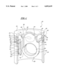
- FIG. 1 is a partially sectioned perspective view of a piston according to the present invention.
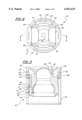
- FIG. 2 is a cross-sectional plan view of a piston according the present invention.
- FIG. 3 is an elevational cross-section of the piston of FIG. 2 taken along line 3--3.
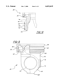
- FIG. 4 is a partial cross sectional view taken along line 4--4 of FIG. 2.
- FIG. 5 is a partial cross-sectional elevational view of the present invention.
- FIG. 1 shows a piston 20 for use in internal combustion engines.
- Piston 20 is of the articulating type having a crown portion 22 separate from a skirt 24.
- Crown portion 22 includes an upper crown 26 connected to a lower crown 28, as for example, by friction welding.
- any suitable connecting techniques e.g. fastening
- Upper crown 26 has an annular outer ring member 30 with a piston ring groove 32 on its outer sidewall 34.
- a combustion bowl 36 is located interior of outer ring member 30 and has an undulating upper surface 38 and a corresponding lower surface 40.
- an annular ridge 42 projects downwardly from lower surface 40.
- An annular recess 44 is formed between sidewall 34 and annular ridge 42.
- lower crown 28 includes at least one annular outer ring member 50 having an outer sidewall 52 and an inner annular ridge 54 that are each positioned to align respectively with outer sidewall 34 and annular ridge 42 of upper crown 26 to facilitate friction welding.
- Annular ring 50 includes an annular recess 56 that is formed between sidewall 52 and annular ridge 54 for corresponding alignment with annular recess 44 of upper crown 26.
- annular recesses 44, 56 cooperate to define a generally continuous cooling chamber 58.
- First and second pin ears 60, 62 project downwardly from lower crown 28 and each have a pin cross bore 64 for receiving a wrist pin (not shown) that is connected to a connecting rod (not shown).
- Pin ears 60, 62 have generally arch-shaped profiles including a base 66, a distal outer tip 68, a front face 70 and a rear face 72.
- first ear 60 further includes a boss 73 located on rear face 72.
- a generally vertical cooling bore 74 is provided in first ear 60 and extends at least partly into boss 73. Cooling bore 74 allows pressurized cooling oil from a conventional oil jet nozzle (not shown) mounted on a cylinder wall (not shown) to be directed up to cooling chamber 58.
- An undercut region 76 is formed in first ear 60 on rear face 72, preferably providing a weight savings advantage.
- the undercut region 76 is produced by a generally circumferential (either continuous or intermittent) undercut (not shown) that removes material from front and rear faces 70, 72 of pin ears 60, 62 in an effort to decrease the weight of piston 20.
- piston 20 is manufactured from a steel forging to provide high strength and relatively low cost. However, any suitable materials or fabricating techniques can be used.
- Undercut region 76 extends into and interrupts cooling bore 74 such that cooling bore 74 includes a discontinuous portion 78.
- a tube member or portion 80 is inserted into a first end 82 of cooling bore 74, near an inlet port 84 of cooling chamber 58.
- Tube 80 extends past discontinuous portion 78 to abut against a shoulder 86.
- tube 80 and cooling bore 74 cooperate to define a generally continuous inlet passageway 88 communicating with cooling chamber 58.
- an outlet port 90 is provided in annular recess 56 of cooling chamber 58 to facilitate drainage and recirculation of oil.
- FIG. 2 shows a cross sectional plan view of piston 20 with skirt 24 and first and second ears 60, 62 being sectioned. Boss 73 is illustrated extending outwardly from rear face 72 of first ear 60. Outlet port 90 is positioned in annular ring 50 approximately midway between first and second ears 60, 62. However, outlet port 90 can be located at any suitable location on lower crown 28. Moreover, although only one inlet passageway 88 and one outlet port 90 are illustrated, it is also contemplated that any suitable number of inlet passageways and outlet ports can be provided according to the present invention.
- FIG. 3 shows a cross section of piston 20 taken through line 3--3 of FIG. 2.
- Cooling bore 74 includes a first section 92 having a first diameter D1 and a second section 94 having a second diameter D2.
- Second diameter D2 is smaller than first diameter D1 and shoulder 86 is formed at the transition between first and second sections 92, 94.
- shoulder 86 acts as a stop to limit the depth of insertion for tube 80 by abuttingly engaging one end 96 of tube 80.
- Opposite end 98 of tube 80 extends into cooling chamber 58 to permit an adequate level of oil to remain in cooling chamber 58 and avoid unwanted drain back through inlet passageway 88.
- tube 80 has an outer diameter slightly smaller than first diameter D1 to provide either a loose fit or an interference fit in cooling bore 74, depending on the desired assembly requirements. Also, tube 80 has an inner diameter that is approximately equal to second diameter D2 to ensure sufficient and even flow of oil. Cooling bore 74 further includes a tapered or flared section 100 provided adjacent to second section 94 to present an enlarged opening for oil to enter from a conventional oil nozzle jet (not shown).
- tube 80 Prior to friction welding upper and lower crowns 26, 28 together, tube 80 is inserted into cooling bore 74 through inlet port 84.
- flash 102 is produced at the interface between upper and lower sidewalls 34, 52 and upper and lower annular ridges 42, 54.
- a machining step is performed to remove any flash that is located on the outer surface of upper and lower sidewalls 34, 52 to provide a generally smooth outer surface.
- such machining cannot be accomplished and is not required on the interior of piston 20.
- FIG. 4 shows a partial cross-section taken along line 4--4 of FIG. 3 with tube 80, skirt 24 and upper crown 26 not shown for clarity.
- First ear 60 is shown in cross-section with second section 94 of cooling bore 74 being interrupted by undercut region 76.
- undercut region 76 extends the full depth of bore 74.
- undercut region 76 may extend deeper or shallower into first ear 60.
- undercut region 76 has a generally V-shaped profile, any suitable shape is envisioned to be used, preferably affording weight savings.
- undercut region 76 is formed by a cutting process after initial fabrication of piston 20. However, undercut region 76 can also be formed during initial fabrication to avoid the need for a subsequent material removal operation, resulting in less scrap.
- FIG. 5 shows a partial cross section of piston 20 with a profile of first ear 60 and boss 73 projecting outwardly from rear face 72.
- Boss 73 is shown extending from base 66 approximately three fourths of the distance to outer tip 68.
- boss 73 can extend and project any suitable distances that provide its function in accordance with the present invention.
- Undercut region 76 is also illustrated near base 66.
- outlet port 90 is shown as an angled opening leading into cooling chamber 58 adjacent sidewall 52 of lower crown 28.
Landscapes
- Engineering & Computer Science (AREA)
- Chemical & Material Sciences (AREA)
- Combustion & Propulsion (AREA)
- Mechanical Engineering (AREA)
- General Engineering & Computer Science (AREA)
- Physics & Mathematics (AREA)
- Fluid Mechanics (AREA)
- Pistons, Piston Rings, And Cylinders (AREA)
Abstract
Description
Claims (19)
Priority Applications (5)
| Application Number | Priority Date | Filing Date | Title |
|---|---|---|---|
| US09/116,165 US6032619A (en) | 1998-07-16 | 1998-07-16 | Piston having a tube to deliver oil for cooling a crown |
| EP99933932A EP1097300B2 (en) | 1998-07-16 | 1999-07-13 | Piston having a tube to deliver oil for cooling a crown |
| PCT/US1999/015748 WO2000004286A1 (en) | 1998-07-16 | 1999-07-13 | Piston having a tube to deliver oil for cooling a crown |
| AU49878/99A AU4987899A (en) | 1998-07-16 | 1999-07-13 | Piston having a tube to deliver oil for cooling a crown |
| DE69917904T DE69917904T3 (en) | 1998-07-16 | 1999-07-13 | PISTON WITH A TUBE FOR THE SUPPLY OF OIL FOR COOLING A PISTON FLOOR |
Applications Claiming Priority (1)
| Application Number | Priority Date | Filing Date | Title |
|---|---|---|---|
| US09/116,165 US6032619A (en) | 1998-07-16 | 1998-07-16 | Piston having a tube to deliver oil for cooling a crown |
Publications (1)
| Publication Number | Publication Date |
|---|---|
| US6032619A true US6032619A (en) | 2000-03-07 |
Family
ID=22365638
Family Applications (1)
| Application Number | Title | Priority Date | Filing Date |
|---|---|---|---|
| US09/116,165 Expired - Lifetime US6032619A (en) | 1998-07-16 | 1998-07-16 | Piston having a tube to deliver oil for cooling a crown |
Country Status (5)
| Country | Link |
|---|---|
| US (1) | US6032619A (en) |
| EP (1) | EP1097300B2 (en) |
| AU (1) | AU4987899A (en) |
| DE (1) | DE69917904T3 (en) |
| WO (1) | WO2000004286A1 (en) |
Cited By (25)
| Publication number | Priority date | Publication date | Assignee | Title |
|---|---|---|---|---|
| US6112642A (en) * | 1998-10-06 | 2000-09-05 | Caterpillar Inc. | Method and apparatus for making a two piece unitary piston |
| US6155157A (en) * | 1998-10-06 | 2000-12-05 | Caterpillar Inc. | Method and apparatus for making a two piece unitary piston |
| US6279455B1 (en) * | 1998-10-06 | 2001-08-28 | Caterpillar Inc. | Method and apparatus for making a two piece unitary piston |
| US6371061B2 (en) | 2000-03-28 | 2002-04-16 | Federal-Mogul World Wide, Inc. | Heavy duty piston having oil splash deflector and method of cooling a piston |
| WO2002050414A1 (en) * | 2000-12-20 | 2002-06-27 | Mahle Gmbh | Cooling duct piston for a direct-injection diesel engine |
| US6491013B1 (en) | 2001-09-19 | 2002-12-10 | Federal-Mogul World Wide, Inc. | Closed gallery piston having reinforced oil hole |
| US6513477B1 (en) | 2001-09-19 | 2003-02-04 | Federal-Mogul World Wide, Inc. | Closed gallery piston having pin bore lubrication |
| US6539910B1 (en) | 2001-09-19 | 2003-04-01 | Federal-Mogul World Wide, Inc. | Closed gallery piston having con rod lubrication |
| US6588320B2 (en) * | 1999-12-30 | 2003-07-08 | Federal-Mogul World Wide, Inc. | Piston having uncoupled skirt |
| US20050092739A1 (en) * | 2003-11-04 | 2005-05-05 | Carmo Ribeiro | Piston and method of manufacture |
| WO2006034862A1 (en) * | 2004-09-29 | 2006-04-06 | Ks Kolbenschmidt Gmbh | Simple friction weld |
| US20070039460A1 (en) * | 2003-10-06 | 2007-02-22 | Rainer Scharp | One-piece piston for an internal combustion engine |
| US20080289490A1 (en) * | 2004-09-09 | 2008-11-27 | Roland Linz | Piston for a Combustion Engine, and Combustion Engine |
| US20090178640A1 (en) * | 2006-06-30 | 2009-07-16 | Daimler Ag | Cast steel piston for internal combustion engines |
| US20090301426A1 (en) * | 2008-06-05 | 2009-12-10 | Hyundai Motor Company | Piston of Engine |
| US20110185992A1 (en) * | 2008-07-24 | 2011-08-04 | Ks Kolbenschmidt Gmbh | Friction welded steel piston having optimized cooling channel |
| US8387571B2 (en) | 2011-11-04 | 2013-03-05 | Ford Global Technologies, Llc | Oil delivery system |
| US20130312695A1 (en) * | 2010-12-18 | 2013-11-28 | Mahle International Gmbh | Piston for an internal combustion engine and method for the production thereof |
| CN103649508A (en) * | 2011-07-04 | 2014-03-19 | 马勒国际公司 | Piston for an internal combustion engine |
| US20150075455A1 (en) * | 2011-09-20 | 2015-03-19 | Mahle International Gmbh | Piston for an internal combustion engine and method for producing same |
| US9108274B2 (en) | 2011-05-05 | 2015-08-18 | Mahle International Gmbh | Method for the production of a piston |
| US20170175671A1 (en) * | 2015-12-18 | 2017-06-22 | Mahle International Gmbh | Piston for an internal combustion engine |
| US20190063364A1 (en) * | 2017-08-29 | 2019-02-28 | General Electric Company | Reciprocating engine |
| US11111878B2 (en) * | 2018-10-29 | 2021-09-07 | Mahle International Gmbh | Piston of an internal-combustion engine |
| US11162453B2 (en) | 2016-05-04 | 2021-11-02 | Ks Kolbenschmidt Gmbh | Piston |
Families Citing this family (7)
| Publication number | Priority date | Publication date | Assignee | Title |
|---|---|---|---|---|
| DE10244512A1 (en) * | 2002-09-25 | 2004-04-15 | Mahle Gmbh | Multi-part cooled piston for an internal combustion engine |
| DE10244511A1 (en) * | 2002-09-25 | 2004-04-15 | Mahle Gmbh | Multi-part cooled piston for an internal combustion engine |
| ATE502200T1 (en) | 2007-08-24 | 2011-04-15 | Thyssenkrupp Metalurgica Campo Limpo Ltda | PISTON FOR AN INTERNAL COMBUSTION ENGINE AND METHOD FOR PRODUCING SUCH A PISTON |
| DE102008011922A1 (en) | 2008-02-29 | 2009-09-03 | Ks Kolbenschmidt Gmbh | Piston for internal combustion engines, produced by means of a multi-orbital friction welding process |
| DE102008034430B4 (en) * | 2008-07-24 | 2015-02-19 | Ks Kolbenschmidt Gmbh | Friction welded steel piston with optimized cooling channel |
| DE102008055848A1 (en) | 2008-11-04 | 2010-05-06 | Ks Kolbenschmidt Gmbh | Cooling channel piston of an internal combustion engine with a closure element which closes the cooling channel |
| DE102015217614B3 (en) * | 2015-09-15 | 2017-02-02 | Federal-Mogul Nürnberg GmbH | Piston for an internal combustion engine and method for producing a piston for an internal combustion engine |
Citations (15)
| Publication number | Priority date | Publication date | Assignee | Title |
|---|---|---|---|---|
| US1073197A (en) * | 1908-04-18 | 1913-09-16 | George Westinghouse | Cooling means for internal-combustion engines. |
| US1157347A (en) * | 1913-12-26 | 1915-10-19 | Gen Electric | Piston-cooling means. |
| US2108194A (en) * | 1935-01-09 | 1938-02-15 | Gen Motors Corp | Piston |
| US2720871A (en) * | 1952-06-23 | 1955-10-18 | Morris Dev Company | Piston and connecting rod assembly |
| US2806750A (en) * | 1955-06-06 | 1957-09-17 | Cooper Bessemer Corp | Piston and piston ring construction |
| US3070079A (en) * | 1960-03-10 | 1962-12-25 | Maybach Motorenbau Gmbh | Gudgeon pin lubricating system |
| US3314402A (en) * | 1965-06-03 | 1967-04-18 | Rostock Dieselmotoren | Apparatus for cooling a piston |
| US3413963A (en) * | 1966-03-18 | 1968-12-03 | Sulzer Ag | Apparatus for liquid cooling of pistons in piston-type internal combustion engines |
| US4011797A (en) * | 1973-07-19 | 1977-03-15 | Dampers Societe Anonyme | Oil-cooled piston for a heat engine |
| US4067307A (en) * | 1973-08-30 | 1978-01-10 | Motoren- Und Turbinen Union Friedrichshafen Gmbh | Free-jet-nozzle |
| US4180027A (en) * | 1977-07-20 | 1979-12-25 | Mack Trucks, Inc. | Two-piece oil-cooled piston |
| US4206726A (en) * | 1977-07-18 | 1980-06-10 | Caterpillar Tractor Co. | Double orifice piston cooling nozzle for reciprocating engines |
| US4581983A (en) * | 1979-05-16 | 1986-04-15 | Karl Schmidt Gmbh | Piston for internal combustion engines |
| US4662319A (en) * | 1984-12-20 | 1987-05-05 | S.E.M.T., S.A. | Structurally lightened piston utilizable especially in an internal combustion engine |
| US4907545A (en) * | 1988-12-28 | 1990-03-13 | Caterpillar Inc. | Liquid cooled piston ring carrier assembly and piston using same |
Family Cites Families (10)
| Publication number | Priority date | Publication date | Assignee | Title |
|---|---|---|---|---|
| FR949304A (en) * | 1939-07-10 | 1949-08-26 | Nordberg Manufacturing Co | Sheath piston |
| FR1024996A (en) * | 1950-03-24 | 1953-04-09 | Piston with cooling device for fast running internal combustion engines, in particular for motor vehicles | |
| DE2348870A1 (en) * | 1973-09-28 | 1975-04-10 | Maschf Augsburg Nuernberg Ag | MULTI-PIECE PISTON FOR COMBUSTION MACHINES, IN PARTICULAR LARGE DIESEL ENGINES |
| DE3719469A1 (en) * | 1987-06-11 | 1988-12-29 | Mahle Gmbh | BUILT LIQUID-COOLED PISTON FOR COMBUSTION ENGINES |
| DE3733964A1 (en) * | 1987-10-08 | 1989-04-20 | Mahle Gmbh | Coolable trunk piston for internal combustion engines |
| DE3830033C2 (en) * | 1987-11-30 | 1998-05-07 | Mahle Gmbh | Built, oil-cooled plunger for internal combustion engines |
| GB8804533D0 (en) * | 1988-02-26 | 1988-03-30 | Wellworthy Ltd | Pistons |
| KR900006661A (en) * | 1988-10-25 | 1990-05-08 | 고하라 도시히토 | Ciramix Metal Friction Presses and the Spiral Mixes |
| BR9001916A (en) * | 1990-04-20 | 1991-11-12 | Metal Leve Sa | PROCESS OF OBTAINING REFRIGERATED PUMP AND REFRIGERATED PUMP |
| DE19603589A1 (en) * | 1996-02-01 | 1997-08-07 | Kolbenschmidt Ag | Pendulum shaft piston |
-
1998
- 1998-07-16 US US09/116,165 patent/US6032619A/en not_active Expired - Lifetime
-
1999
- 1999-07-13 WO PCT/US1999/015748 patent/WO2000004286A1/en active IP Right Grant
- 1999-07-13 AU AU49878/99A patent/AU4987899A/en not_active Abandoned
- 1999-07-13 DE DE69917904T patent/DE69917904T3/en not_active Expired - Lifetime
- 1999-07-13 EP EP99933932A patent/EP1097300B2/en not_active Expired - Lifetime
Patent Citations (15)
| Publication number | Priority date | Publication date | Assignee | Title |
|---|---|---|---|---|
| US1073197A (en) * | 1908-04-18 | 1913-09-16 | George Westinghouse | Cooling means for internal-combustion engines. |
| US1157347A (en) * | 1913-12-26 | 1915-10-19 | Gen Electric | Piston-cooling means. |
| US2108194A (en) * | 1935-01-09 | 1938-02-15 | Gen Motors Corp | Piston |
| US2720871A (en) * | 1952-06-23 | 1955-10-18 | Morris Dev Company | Piston and connecting rod assembly |
| US2806750A (en) * | 1955-06-06 | 1957-09-17 | Cooper Bessemer Corp | Piston and piston ring construction |
| US3070079A (en) * | 1960-03-10 | 1962-12-25 | Maybach Motorenbau Gmbh | Gudgeon pin lubricating system |
| US3314402A (en) * | 1965-06-03 | 1967-04-18 | Rostock Dieselmotoren | Apparatus for cooling a piston |
| US3413963A (en) * | 1966-03-18 | 1968-12-03 | Sulzer Ag | Apparatus for liquid cooling of pistons in piston-type internal combustion engines |
| US4011797A (en) * | 1973-07-19 | 1977-03-15 | Dampers Societe Anonyme | Oil-cooled piston for a heat engine |
| US4067307A (en) * | 1973-08-30 | 1978-01-10 | Motoren- Und Turbinen Union Friedrichshafen Gmbh | Free-jet-nozzle |
| US4206726A (en) * | 1977-07-18 | 1980-06-10 | Caterpillar Tractor Co. | Double orifice piston cooling nozzle for reciprocating engines |
| US4180027A (en) * | 1977-07-20 | 1979-12-25 | Mack Trucks, Inc. | Two-piece oil-cooled piston |
| US4581983A (en) * | 1979-05-16 | 1986-04-15 | Karl Schmidt Gmbh | Piston for internal combustion engines |
| US4662319A (en) * | 1984-12-20 | 1987-05-05 | S.E.M.T., S.A. | Structurally lightened piston utilizable especially in an internal combustion engine |
| US4907545A (en) * | 1988-12-28 | 1990-03-13 | Caterpillar Inc. | Liquid cooled piston ring carrier assembly and piston using same |
Cited By (48)
| Publication number | Priority date | Publication date | Assignee | Title |
|---|---|---|---|---|
| US6155157A (en) * | 1998-10-06 | 2000-12-05 | Caterpillar Inc. | Method and apparatus for making a two piece unitary piston |
| US6279455B1 (en) * | 1998-10-06 | 2001-08-28 | Caterpillar Inc. | Method and apparatus for making a two piece unitary piston |
| US6112642A (en) * | 1998-10-06 | 2000-09-05 | Caterpillar Inc. | Method and apparatus for making a two piece unitary piston |
| US6588320B2 (en) * | 1999-12-30 | 2003-07-08 | Federal-Mogul World Wide, Inc. | Piston having uncoupled skirt |
| US6371061B2 (en) | 2000-03-28 | 2002-04-16 | Federal-Mogul World Wide, Inc. | Heavy duty piston having oil splash deflector and method of cooling a piston |
| US20040045515A1 (en) * | 2000-12-20 | 2004-03-11 | Ulrich Bischofberger | Cooling duct piston for a direct-injection diesel engine |
| KR100762527B1 (en) | 2000-12-20 | 2007-10-01 | 말레 게엠베하 | Cooling duct piston for a direct-injection diesel engine |
| WO2002050414A1 (en) * | 2000-12-20 | 2002-06-27 | Mahle Gmbh | Cooling duct piston for a direct-injection diesel engine |
| US6892689B2 (en) | 2000-12-20 | 2005-05-17 | Mahle Gmbh | Cooling duct piston for a direct-injection diesel engine |
| US6513477B1 (en) | 2001-09-19 | 2003-02-04 | Federal-Mogul World Wide, Inc. | Closed gallery piston having pin bore lubrication |
| US6539910B1 (en) | 2001-09-19 | 2003-04-01 | Federal-Mogul World Wide, Inc. | Closed gallery piston having con rod lubrication |
| US6491013B1 (en) | 2001-09-19 | 2002-12-10 | Federal-Mogul World Wide, Inc. | Closed gallery piston having reinforced oil hole |
| EP1427921A1 (en) * | 2001-09-19 | 2004-06-16 | Federal-Mogul Corporation | Closed gallery piston having reinforced oil hole |
| EP1427921A4 (en) * | 2001-09-19 | 2004-11-10 | Federal Mogul Corp | Closed gallery piston having reinforced oil hole |
| US7409903B2 (en) * | 2003-10-06 | 2008-08-12 | Mahle Gmbh | One-piece piston for an internal combustion engine |
| US20070039460A1 (en) * | 2003-10-06 | 2007-02-22 | Rainer Scharp | One-piece piston for an internal combustion engine |
| US7005620B2 (en) | 2003-11-04 | 2006-02-28 | Federal-Mogul World Wide, Inc. | Piston and method of manufacture |
| US20050092739A1 (en) * | 2003-11-04 | 2005-05-05 | Carmo Ribeiro | Piston and method of manufacture |
| US20080289490A1 (en) * | 2004-09-09 | 2008-11-27 | Roland Linz | Piston for a Combustion Engine, and Combustion Engine |
| US7748361B2 (en) * | 2004-09-09 | 2010-07-06 | Federal-Mogul Nurnberg Gmbh | Piston for a combustion engine, and combustion engine |
| WO2006034862A1 (en) * | 2004-09-29 | 2006-04-06 | Ks Kolbenschmidt Gmbh | Simple friction weld |
| US20100275873A1 (en) * | 2004-09-29 | 2010-11-04 | Ks Kolbenschmidt Gmbh | Simple frictional weld |
| US10066579B2 (en) | 2004-09-29 | 2018-09-04 | Ks Kolbenschmidt Gmbh | Simple friction weld |
| US8528513B2 (en) * | 2006-06-30 | 2013-09-10 | Daimler Ag | Cast steel piston for internal combustion engines |
| US20090178640A1 (en) * | 2006-06-30 | 2009-07-16 | Daimler Ag | Cast steel piston for internal combustion engines |
| US20090301426A1 (en) * | 2008-06-05 | 2009-12-10 | Hyundai Motor Company | Piston of Engine |
| US8408167B2 (en) * | 2008-06-05 | 2013-04-02 | Hyundai Motor Company | Piston of engine |
| US20110185992A1 (en) * | 2008-07-24 | 2011-08-04 | Ks Kolbenschmidt Gmbh | Friction welded steel piston having optimized cooling channel |
| US9238283B2 (en) * | 2008-07-24 | 2016-01-19 | Ks Kolbenschmidt Gmbh | Friction welded steel piston having optimized cooling channel |
| US8899208B2 (en) * | 2010-12-18 | 2014-12-02 | Mahle International Gmbh | Internal combustion engine piston having axially extending cooling bores |
| US20130312695A1 (en) * | 2010-12-18 | 2013-11-28 | Mahle International Gmbh | Piston for an internal combustion engine and method for the production thereof |
| US9108274B2 (en) | 2011-05-05 | 2015-08-18 | Mahle International Gmbh | Method for the production of a piston |
| US9364923B2 (en) | 2011-05-05 | 2016-06-14 | Mahle International Gmbh | Method for the production of a piston |
| CN103649508B (en) * | 2011-07-04 | 2016-06-29 | 马勒国际公司 | Piston for internal combustion engine |
| CN103649508A (en) * | 2011-07-04 | 2014-03-19 | 马勒国际公司 | Piston for an internal combustion engine |
| US20140130767A1 (en) * | 2011-07-04 | 2014-05-15 | Mahle International Gmbh | Piston for an internal combustion engine |
| US9341137B2 (en) * | 2011-07-04 | 2016-05-17 | Mahle International Gmbh | Piston for an internal combustion engine |
| US10731599B2 (en) * | 2011-09-20 | 2020-08-04 | Mahle International Gmbh | Piston for an internal combustion engine and method for producing same |
| CN107842439A (en) * | 2011-09-20 | 2018-03-27 | 马勒国际公司 | Internal combustion engine and its manufacture method |
| US20150075455A1 (en) * | 2011-09-20 | 2015-03-19 | Mahle International Gmbh | Piston for an internal combustion engine and method for producing same |
| US8387571B2 (en) | 2011-11-04 | 2013-03-05 | Ford Global Technologies, Llc | Oil delivery system |
| US20170175671A1 (en) * | 2015-12-18 | 2017-06-22 | Mahle International Gmbh | Piston for an internal combustion engine |
| US10227948B2 (en) * | 2015-12-18 | 2019-03-12 | Mahle International Gmbh | Piston for an internal combustion engine |
| US11162453B2 (en) | 2016-05-04 | 2021-11-02 | Ks Kolbenschmidt Gmbh | Piston |
| US20190063364A1 (en) * | 2017-08-29 | 2019-02-28 | General Electric Company | Reciprocating engine |
| US11060479B2 (en) * | 2017-08-29 | 2021-07-13 | General Electric Company | Reciprocating engine |
| US11732672B2 (en) | 2017-08-29 | 2023-08-22 | General Electric Company | Reciprocating engine |
| US11111878B2 (en) * | 2018-10-29 | 2021-09-07 | Mahle International Gmbh | Piston of an internal-combustion engine |
Also Published As
| Publication number | Publication date |
|---|---|
| DE69917904T3 (en) | 2007-05-24 |
| DE69917904D1 (en) | 2004-07-15 |
| DE69917904T2 (en) | 2005-06-09 |
| EP1097300A1 (en) | 2001-05-09 |
| AU4987899A (en) | 2000-02-07 |
| EP1097300B1 (en) | 2004-06-09 |
| WO2000004286A1 (en) | 2000-01-27 |
| EP1097300B2 (en) | 2007-01-17 |
Similar Documents
| Publication | Publication Date | Title |
|---|---|---|
| US6032619A (en) | Piston having a tube to deliver oil for cooling a crown | |
| US6513477B1 (en) | Closed gallery piston having pin bore lubrication | |
| US4377967A (en) | Two-piece piston assembly | |
| US7406941B2 (en) | One piece cast steel monobloc piston | |
| US7997249B2 (en) | Piston for internal combustion engine and internal combustion engine with the same | |
| US6539910B1 (en) | Closed gallery piston having con rod lubrication | |
| EP1427921B1 (en) | Closed gallery piston having reinforced oil hole | |
| EP1438493B1 (en) | Closed gallery monobloc piston having oil drainage groove | |
| US7954421B2 (en) | Lightweight piston | |
| US20120037112A1 (en) | Steel piston with cooling gallery and method of construction thereof | |
| KR20080080546A (en) | Piston for an internal combustion engine and method of producing it | |
| US20080121102A1 (en) | Two-Part Piston For a Combustion Engine | |
| JP2004515359A5 (en) | ||
| US6152016A (en) | Piston with cast passages | |
| RU2190773C2 (en) | Piston for double-stroke diesel engine with crosshead | |
| US20020056367A1 (en) | Piston for an internal combustion engine and method of assembly | |
| EP3864276B1 (en) | Piston cooling gallery shaping to reduce piston temperature | |
| CN109154252A (en) | With the cooling of improved sack-like element without passage piston | |
| US6314864B1 (en) | Closed cavity piston for hydrostatic units | |
| US20080295683A1 (en) | Focal oiling for a piston assembly | |
| WO2004033884A1 (en) | Cylinder liner | |
| US20180087470A1 (en) | Piston ring-belt structural reinforcement via additive machining | |
| CN107387253A (en) | A kind of piston and its manufacture method | |
| JPH05321626A (en) | Coupling structure between piston and connecting rod | |
| JPH0814266B2 (en) | Connection structure of piston and connecting rod |
Legal Events
| Date | Code | Title | Description |
|---|---|---|---|
| AS | Assignment |
Owner name: FEDERAL-MOGUL WORLD WIDE, INC., MICHIGAN Free format text: ASSIGNMENT OF ASSIGNORS INTEREST;ASSIGNORS:ZHU, XILUO;BROWN, ALAN S.;REEL/FRAME:009335/0569 Effective date: 19980603 |
|
| FEPP | Fee payment procedure |
Free format text: PAYOR NUMBER ASSIGNED (ORIGINAL EVENT CODE: ASPN); ENTITY STATUS OF PATENT OWNER: LARGE ENTITY |
|
| FEPP | Fee payment procedure |
Free format text: PAYER NUMBER DE-ASSIGNED (ORIGINAL EVENT CODE: RMPN); ENTITY STATUS OF PATENT OWNER: LARGE ENTITY Free format text: PAYOR NUMBER ASSIGNED (ORIGINAL EVENT CODE: ASPN); ENTITY STATUS OF PATENT OWNER: LARGE ENTITY |
|
| STCF | Information on status: patent grant |
Free format text: PATENTED CASE |
|
| AS | Assignment |
Owner name: WILMINGTON TRUST COMPANY, AS TRUSTEE, DELAWARE Free format text: SECURITY AGREEMENT;ASSIGNOR:FEDERAL-MOGUL WORLD WIDE, INC. (MI CORPORATION);REEL/FRAME:011571/0001 Effective date: 20001229 |
|
| FPAY | Fee payment |
Year of fee payment: 4 |
|
| FPAY | Fee payment |
Year of fee payment: 8 |
|
| AS | Assignment |
Owner name: FEDERAL-MOGUL WORLDWIDE, INC., MICHIGAN Free format text: RELEASE OF SECURITY INTEREST RECORDED AT REEL/FRAME 011571/0001 AND 011466/0001;ASSIGNOR:WILMINGTON TRUST COMPANY, AS TRUSTEE;REEL/FRAME:020299/0377 Effective date: 20071217 |
|
| AS | Assignment |
Owner name: CITIBANK, N.A. AS COLLATERAL TRUSTEE, NEW YORK Free format text: SECURITY AGREEMENT;ASSIGNOR:FEDERAL-MOGUL WORLD WIDE, INC.;REEL/FRAME:020362/0139 Effective date: 20071227 Owner name: CITIBANK, N.A. AS COLLATERAL TRUSTEE,NEW YORK Free format text: SECURITY AGREEMENT;ASSIGNOR:FEDERAL-MOGUL WORLD WIDE, INC.;REEL/FRAME:020362/0139 Effective date: 20071227 |
|
| FPAY | Fee payment |
Year of fee payment: 12 |
|
| AS | Assignment |
Owner name: CITIBANK, N.A., AS COLLATERAL TRUSTEE, DELAWARE Free format text: SECURITY INTEREST;ASSIGNORS:FEDERAL-MOGUL CORPORATION, A DELAWARE CORPORATION;FEDERAL-MOGUL WORLD WIDE, INC., A MICHIGAN CORPORATION;FEDERAL-MOGUL IGNITION COMPANY, A DELAWARE CORPORATION;AND OTHERS;REEL/FRAME:033204/0707 Effective date: 20140616 |
|
| AS | Assignment |
Owner name: CITIBANK, N.A., AS COLLATERAL TRUSTEE, NEW YORK Free format text: GRANT OF SECURITY INTEREST IN UNITED STATES PATENTS;ASSIGNORS:FEDERAL-MOGUL LLC;FEDERAL-MOGUL PRODUCTS, INC.;FEDERAL-MOGUL MOTORPARTS CORPORATION;AND OTHERS;REEL/FRAME:042963/0662 Effective date: 20170330 |
|
| AS | Assignment |
Owner name: CITIBANK, N.A., AS COLLATERAL TRUSTEE, NEW YORK Free format text: GRANT OF SECURITY INTEREST IN UNITED STATES PATENTS;ASSIGNORS:FEDERAL-MOGUL LLC;FEDERAL-MOGUL PRODUCTS, INC.;FEDERAL-MOGUL MOTORPARTS LLC;AND OTHERS;REEL/FRAME:044013/0419 Effective date: 20170629 |
|
| AS | Assignment |
Owner name: FEDERAL-MOGUL WORLD WIDE LLC, MICHIGAN Free format text: CHANGE OF NAME;ASSIGNOR:FEDERAL-MOGUL WORLD WIDE, INC.;REEL/FRAME:044033/0437 Effective date: 20170410 |
|
| AS | Assignment |
Owner name: BANK OF AMERICA, N.A., AS COLLATERAL TRUSTEE, MICHIGAN Free format text: COLLATERAL TRUSTEE RESIGNATION AND APPOINTMENT AGREEMENT;ASSIGNOR:CITIBANK, N.A., AS COLLATERAL TRUSTEE;REEL/FRAME:045822/0765 Effective date: 20180223 Owner name: BANK OF AMERICA, N.A., AS COLLATERAL TRUSTEE, MICH Free format text: COLLATERAL TRUSTEE RESIGNATION AND APPOINTMENT AGREEMENT;ASSIGNOR:CITIBANK, N.A., AS COLLATERAL TRUSTEE;REEL/FRAME:045822/0765 Effective date: 20180223 |
|
| AS | Assignment |
Owner name: FEDERAL-MOGUL CHASSIS LLC, MICHIGAN Free format text: RELEASE BY SECURED PARTY;ASSIGNOR:BANK OF AMERICA, N.A., AS COLLATERAL TRUSTEE;REEL/FRAME:047276/0554 Effective date: 20181001 Owner name: FEDERAL-MOGUL PRODUCTS, INC., MICHIGAN Free format text: RELEASE BY SECURED PARTY;ASSIGNOR:BANK OF AMERICA, N.A., AS COLLATERAL TRUSTEE;REEL/FRAME:047276/0554 Effective date: 20181001 Owner name: FEDERAL-MOGUL WORLD WIDE LLC, MICHIGAN Free format text: RELEASE BY SECURED PARTY;ASSIGNOR:BANK OF AMERICA, N.A., AS COLLATERAL TRUSTEE;REEL/FRAME:047276/0554 Effective date: 20181001 Owner name: FEDERAL-MOGUL MOTORPARTS LLC, MICHIGAN Free format text: RELEASE BY SECURED PARTY;ASSIGNOR:BANK OF AMERICA, N.A., AS COLLATERAL TRUSTEE;REEL/FRAME:047276/0554 Effective date: 20181001 Owner name: FEDERAL-MOGUL LLC, MICHIGAN Free format text: RELEASE BY SECURED PARTY;ASSIGNOR:BANK OF AMERICA, N.A., AS COLLATERAL TRUSTEE;REEL/FRAME:047276/0554 Effective date: 20181001 Owner name: FEDERAL-MOGUL IGNITION COMPANY, MICHIGAN Free format text: RELEASE BY SECURED PARTY;ASSIGNOR:BANK OF AMERICA, N.A., AS COLLATERAL TRUSTEE;REEL/FRAME:047276/0554 Effective date: 20181001 Owner name: FEDERAL MOGUL POWERTRAIN LLC, MICHIGAN Free format text: RELEASE BY SECURED PARTY;ASSIGNOR:BANK OF AMERICA, N.A., AS COLLATERAL TRUSTEE;REEL/FRAME:047276/0554 Effective date: 20181001 Owner name: FEDERAL-MOGUL PRODUCTS, INC., MICHIGAN Free format text: RELEASE BY SECURED PARTY;ASSIGNOR:BANK OF AMERICA, N.A., AS COLLATERAL TRUSTEE;REEL/FRAME:047276/0771 Effective date: 20181001 Owner name: FEDERAL-MOGUL WORLD WIDE LLC, MICHIGAN Free format text: RELEASE BY SECURED PARTY;ASSIGNOR:BANK OF AMERICA, N.A., AS COLLATERAL TRUSTEE;REEL/FRAME:047276/0771 Effective date: 20181001 Owner name: FEDERAL-MOGUL MOTORPARTS LLC, MICHIGAN Free format text: RELEASE BY SECURED PARTY;ASSIGNOR:BANK OF AMERICA, N.A., AS COLLATERAL TRUSTEE;REEL/FRAME:047276/0771 Effective date: 20181001 Owner name: FEDERAL-MOGUL CHASSIS LLC, MICHIGAN Free format text: RELEASE BY SECURED PARTY;ASSIGNOR:BANK OF AMERICA, N.A., AS COLLATERAL TRUSTEE;REEL/FRAME:047276/0771 Effective date: 20181001 Owner name: FEDERAL-MOGUL LLC, MICHIGAN Free format text: RELEASE BY SECURED PARTY;ASSIGNOR:BANK OF AMERICA, N.A., AS COLLATERAL TRUSTEE;REEL/FRAME:047276/0771 Effective date: 20181001 Owner name: FEDERAL-MOGUL IGNITION COMPANY, MICHIGAN Free format text: RELEASE BY SECURED PARTY;ASSIGNOR:BANK OF AMERICA, N.A., AS COLLATERAL TRUSTEE;REEL/FRAME:047276/0771 Effective date: 20181001 Owner name: FEDERAL MOGUL POWERTRAIN LLC, MICHIGAN Free format text: RELEASE BY SECURED PARTY;ASSIGNOR:BANK OF AMERICA, N.A., AS COLLATERAL TRUSTEE;REEL/FRAME:047276/0771 Effective date: 20181001 |
|
| AS | Assignment |
Owner name: WILMINGTON TRUST, NATIONAL ASSOCIATION, AS CO-COLLATERAL TRUSTEE, SUCCESSOR COLLATERAL TRUSTEE, MINNESOTA Free format text: COLLATERAL TRUSTEE RESIGNATION AND APPOINTMENT, JOINDER, ASSUMPTION AND DESIGNATION AGREEMENT;ASSIGNOR:BANK OF AMERICA, N.A., AS CO-COLLATERAL TRUSTEE AND RESIGNING COLLATERAL TRUSTEE;REEL/FRAME:047630/0661 Effective date: 20181001 Owner name: WILMINGTON TRUST, NATIONAL ASSOCIATION, AS CO-COLL Free format text: COLLATERAL TRUSTEE RESIGNATION AND APPOINTMENT, JOINDER, ASSUMPTION AND DESIGNATION AGREEMENT;ASSIGNOR:BANK OF AMERICA, N.A., AS CO-COLLATERAL TRUSTEE AND RESIGNING COLLATERAL TRUSTEE;REEL/FRAME:047630/0661 Effective date: 20181001 |
|
| AS | Assignment |
Owner name: DRIV AUTOMOTIVE INC., ILLINOIS Free format text: RELEASE BY SECURED PARTY;ASSIGNOR:WILMINGTON TRUST, NATIONAL ASSOCIATION;REEL/FRAME:058392/0274 Effective date: 20210317 Owner name: FEDERAL-MOGUL POWERTRAIN LLC, MICHIGAN Free format text: RELEASE BY SECURED PARTY;ASSIGNOR:WILMINGTON TRUST, NATIONAL ASSOCIATION;REEL/FRAME:058392/0274 Effective date: 20210317 Owner name: FEDERAL-MOGUL CHASSIS LLC, MICHIGAN Free format text: RELEASE BY SECURED PARTY;ASSIGNOR:WILMINGTON TRUST, NATIONAL ASSOCIATION;REEL/FRAME:058392/0274 Effective date: 20210317 Owner name: TENNECO INC., AS SUCCESSOR TO FEDERAL-MOGUL LLC, ILLINOIS Free format text: RELEASE BY SECURED PARTY;ASSIGNOR:WILMINGTON TRUST, NATIONAL ASSOCIATION;REEL/FRAME:058392/0274 Effective date: 20210317 Owner name: FEDERAL-MOGUL IGNITION, LLC, AS SUCCESSOR TO FEDERAL-MOGUL IGNITION COMPANY, MICHIGAN Free format text: RELEASE BY SECURED PARTY;ASSIGNOR:WILMINGTON TRUST, NATIONAL ASSOCIATION;REEL/FRAME:058392/0274 Effective date: 20210317 Owner name: FEDERAL-MOGUL MOTORPARTS LLC, AS SUCCESSOR TO FEDERAL-MOGUL MOTORPARTS CORPORATION, MICHIGAN Free format text: RELEASE BY SECURED PARTY;ASSIGNOR:WILMINGTON TRUST, NATIONAL ASSOCIATION;REEL/FRAME:058392/0274 Effective date: 20210317 Owner name: FEDERAL-MOGUL WORLD WIDE, INC., AS SUCCESSOR TO FEDERAL-MOGUL WORLD WIDE LLC, MICHIGAN Free format text: RELEASE BY SECURED PARTY;ASSIGNOR:WILMINGTON TRUST, NATIONAL ASSOCIATION;REEL/FRAME:058392/0274 Effective date: 20210317 Owner name: FEDERAL-MOGUL PRODUCTS US, LLC, AS SUCCESSOR TO FEDERAL-MOGUL PRODUCTS, INC., MICHIGAN Free format text: RELEASE BY SECURED PARTY;ASSIGNOR:WILMINGTON TRUST, NATIONAL ASSOCIATION;REEL/FRAME:058392/0274 Effective date: 20210317 Owner name: FEDERAL-MOGUL PRODUCTS US, LLC, AS SUCCESSOR TO FEDERAL-MOGUL PRODUCTS, INC., MICHIGAN Free format text: RELEASE BY SECURED PARTY;ASSIGNOR:WILMINGTON TRUST, NATIONAL ASSOCIATION;REEL/FRAME:056886/0455 Effective date: 20210317 Owner name: FEDERAL-MOGUL WORLD WIDE, INC., AS SUCCESSOR TO FEDERAL-MOGUL WORLD WIDE LLC, MICHIGAN Free format text: RELEASE BY SECURED PARTY;ASSIGNOR:WILMINGTON TRUST, NATIONAL ASSOCIATION;REEL/FRAME:056886/0455 Effective date: 20210317 Owner name: FEDERAL-MOGUL MOTORPARTS LLC, AS SUCCESSOR TO FEDERAL-MOGUL MOTORPARTS CORPORATION, MICHIGAN Free format text: RELEASE BY SECURED PARTY;ASSIGNOR:WILMINGTON TRUST, NATIONAL ASSOCIATION;REEL/FRAME:056886/0455 Effective date: 20210317 Owner name: FEDERAL-MOGUL IGNITION, LLC, AS SUCCESSOR TO FEDERAL-MOGUL IGNITION COMPANY, MICHIGAN Free format text: RELEASE BY SECURED PARTY;ASSIGNOR:WILMINGTON TRUST, NATIONAL ASSOCIATION;REEL/FRAME:056886/0455 Effective date: 20210317 Owner name: TENNECO INC., AS SUCCESSOR TO FEDERAL-MOGUL LLC, ILLINOIS Free format text: RELEASE BY SECURED PARTY;ASSIGNOR:WILMINGTON TRUST, NATIONAL ASSOCIATION;REEL/FRAME:056886/0455 Effective date: 20210317 Owner name: FEDERAL-MOGUL CHASSIS LLC, MICHIGAN Free format text: RELEASE BY SECURED PARTY;ASSIGNOR:WILMINGTON TRUST, NATIONAL ASSOCIATION;REEL/FRAME:056886/0455 Effective date: 20210317 Owner name: FEDERAL-MOGUL POWERTRAIN LLC, MICHIGAN Free format text: RELEASE BY SECURED PARTY;ASSIGNOR:WILMINGTON TRUST, NATIONAL ASSOCIATION;REEL/FRAME:056886/0455 Effective date: 20210317 Owner name: DRIV AUTOMOTIVE INC., ILLINOIS Free format text: RELEASE BY SECURED PARTY;ASSIGNOR:WILMINGTON TRUST, NATIONAL ASSOCIATION;REEL/FRAME:056886/0455 Effective date: 20210317 |
|
| AS | Assignment |
Owner name: CITIBANK, N.A., AS COLLATERAL AGENT, NEW YORK Free format text: NOTICE OF GRANT OF SECURITY INTEREST IN PATENTS (FIRST LIEN);ASSIGNORS:DRIV AUTOMOTIVE INC.;FEDERAL-MOGUL CHASSIS LLC;FEDERAL-MOGUL IGNITION LLC;AND OTHERS;REEL/FRAME:061989/0689 Effective date: 20221117 |
|
| AS | Assignment |
Owner name: FEDERAL-MOGUL WORLD WIDE LLC (FORMERLY FEDERAL-MOGUL WORLD WIDE, INC.), MICHIGAN Free format text: RELEASE BY SECURED PARTY;ASSIGNOR:CITIBANK, N.A.;REEL/FRAME:062389/0149 Effective date: 20230112 |
|
| AS | Assignment |
Owner name: CITIBANK, N.A., AS COLLATERAL AGENT, NEW YORK Free format text: PATENT SECURITY AGREEMENT (ABL);ASSIGNORS:TENNECO INC.;DRIV AUTOMOTIVE INC.;FEDERAL-MOGUL CHASSIS LLC;AND OTHERS;REEL/FRAME:063268/0506 Effective date: 20230406 |